

Ganz ZN-PTZ12VN-XT User Manual
CAUTION
RISK OF ELECTRIC SHOCK,
DO NOT OPEN
!
CAUTION: TO REDUCE THE RISK OF ELECTRIC SHOCK,
DO NOT REMOVE COVER (OR BACK).
NO USER SERVICEABLE PARTS INSIDE.
REFER SERVICING TO QUALIFIED SEERIVCE PERSONEL.
This symbol is intended to alert the user to the presence of un-insulated
“dangerous voltage” within the product’s enclosure that may be of sufficient
magnitude to constitute a risk of electric shock to persons.
!
This symbol is intended to alert the user to the presence of important
operating and maintenance (servicing) instructions in the literature
accompanying the appliance.
INFORMATION TO USER

NVC/IPE Series Installation Guide IPE5510 Installation Guide
Table of Contents
1. FEATURES ................................................................................................................. 4
2. PACKAGE CONTENTS ................................................................................................ 5
3. PART NAMES ............................................................................................................ 6
4. INSTALLATION .......................................................................................................... 8
4.1. Installation Template ...................................................................................................... 9
4.2.Setting the Image Attribute ........................................................................................... 10
4.3.Operating the OSD Menu .............................................................................................. 10
5. CONNECTIONS ........................................................................................................ 11
5.1.Connectors .................................................................................................................... 11
6. CONFIGURATION .................................................................................................... 14
6.1.Set up network environment ......................................................................................... 14
6.2. View video on web page ............................................................................................... 14
6.2.1. View video using IPAdmin Tool .............................................................................. 14
6.2.2. View video using IP address ................................................................................... 16
6.3. Reset ............................................................................................................................ 16
6.4. Factory Default ............................................................................................................. 16
APPENDIX (A): SPECIFICATIONS.................................................................................. 17
Summary ............................................................................................................................ 17
Electrical Characteristics ..................................................................................................... 18
Environment Condition ....................................................................................................... 18
APPENDIX (B): DIMENSIONS....................................................................................... 19
APPENDIX (C): HEXADECIMAL-DECIMAL CONVERSION TABLE ................................... 20
REVISION HISTORY ..................................................................................................... 21
01A.02 3

NVC/IPE Series Installation Guide IPE5510 Installation Guide
1. FEATURES
Camera
Indoor/Outdoor Mini PTZ Dome IP Camera (Vandal Proof)
Sony 1/4” Super HAD CCD, 410K Pixel
x12 Optical Zoom, x16 Digital Zoom (Max x192)
True Day & Night (IR Cut Filter, DSS)
360° endless rotation
Intelligent pan/tilt controlling
Improvement of color rolling suppression
Streaming
Dual streaming mode (such as different codec/resolution/bit rate and so on.)
De-interlacing on DSP
Burnt-in text supported
Unicast/Multicast supported
Video/Audio
Video compression: H.264/MPEG4/MJPEG, 25/30FPS@D1(PAL/NTSC)
Audio compression: G.711(µLaw, aLaw)/PCM
Analog video out for external monitors
Video Motion Detection supported
Two-way mono audio supported
Network
RTSP/ HTTP protocol supported
10/100 Base-T Ethernet
Additional Features
RS-485 supported
Micro SD card socket for external storage
OSD supported
SDK (Software Development Kit) provided
VCA (Video Content Analysis)
VCA Presence (Included as basic)
VCA Surveillance (Optional)
01A.02 4
NVC/IPE Series Installation Guide IPE5510 Installation Guide
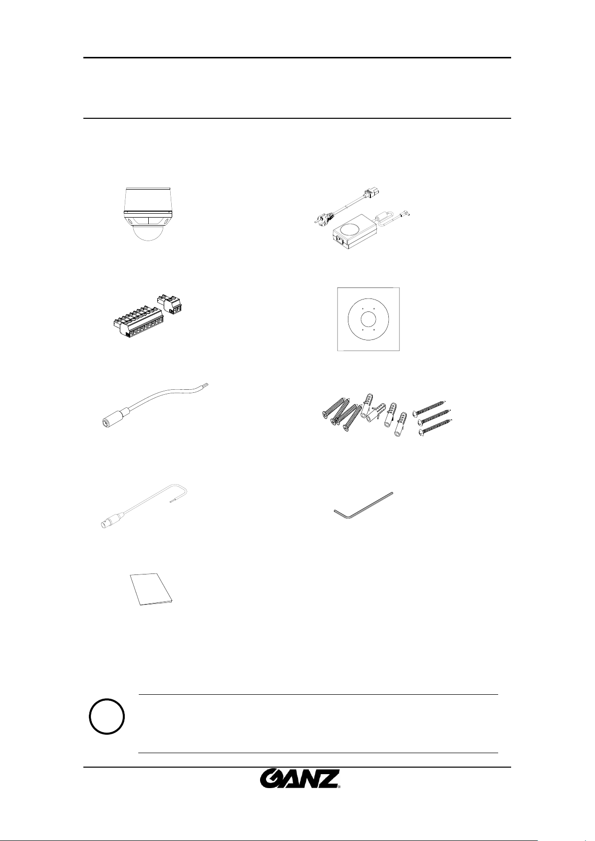
Camera
DC power adaptor
Terminal block
Installation Template
Power adaptor jack
Screws and Anchor blocks
Video BNC cable
Hex wrench driver
Quick Installation Guide
Note
i
The above contents are subject to change without prior notice.
2. PACKAGE CONTENTS
Unpack carefully and handle the equipment with care. The packaging contains:
01A.02 5
NVC/IPE Series Installation Guide IPE5510 Installation Guide
①
②
③
④
⑤
* Models herein and their appearance
are subject to change without any prior
notice.
In
Out
AUDIODIDO RS-485
12VVout
In
Out
AUDIO
DI
DO RS-485
12V
Vout
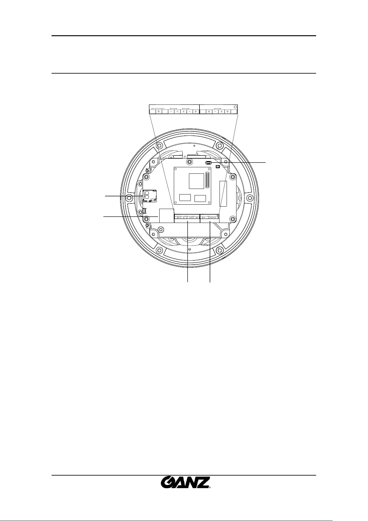
3. PART NAMES
01A.02 6
NVC/IPE Series Installation Guide IPE5510 Installation Guide
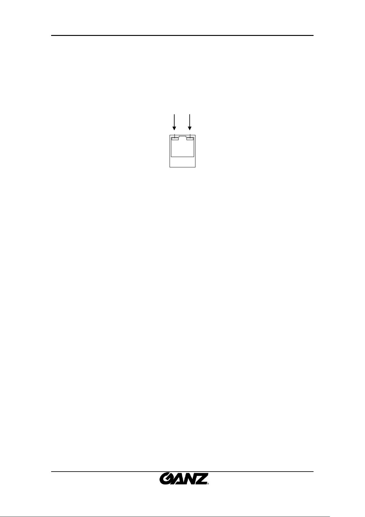
LED1 LED2
① Micro SD Card Socket
It is a memory card slot for external storage.
② LAN Connector (Ethernet)
This is a RJ45 LAN connector for 10/100 Base-T Ethernet.
This LED lights up as orange and turns green when the encoder is powered on.
LED operation setting:
For the factory default setting, LED 2 blinks for the heartbeat and LED 1 turns on for video
signal. To change its setting, refer to the section 4.5.11. LED Setting of the NVC Web Page
User’s Manual.
③ 8 pin terminal block for audio, DI, and DO
Refer to the section “5.1.Connectors” for more specific information.
④ 6 pin connector for analog video output, RS485, and power
Refer to the section “5.1.Connectors” for more specific information.
⑤ Reset
Reset switch is used for restarting the camera or resetting it to Factory Default (FD). Refer to
the section “6.3. Reset” for more specific information.
01A.02 7
 Loading...