

Ganz ZN-PT series Installation Manual
Integrated High Speed Dome Camera
Outdoor
Installation Guide
Version 3.6

Preface
Information given in this manual was current when published. The company reserves the
right to revise and improve its products. All specifications are subject to change without
notice.
Notice
This manual provides installation information for the outdoor Integrated High
Speed Dome Camera. To work with the Dome Cameras, any installer or
technician must have the following minimum qualifications:
• A basic knowledge of CCTV systems and components
• A basic knowledge of electrical wiring and low-voltage electrical
hookups
• A basic knowledge of network system setting
• Have read this manual completely
Copyright
Under copyright laws, the contents of this installation guide may not be copied,
photocopied, translated, reproduced or reduced to any electronic medium or
machine-readable format, in whole or in part, without prior written permission
of the company.
Important Information
Before proceeding, please read and observe all instructions and warnings in
this manual. Retain this manual with the original bill of sale for future
reference and, if necessary, warranty service. When unpacking your unit,
check for missing or damaged items. If any item is missing, or if damage is
evident, DO NOT INSTALL OR OPERATE THIS PRODUCT. Contact your
dealer for assistance.
Regulation
This device complies with Part 15 of the FCC Rules.
Operation is subject to the following two conditions:
(1) this device may not cause harmful interference, and (2)
this device must accept any interference received, including
interference that may cause undesired operation.
Installation Guide
ii
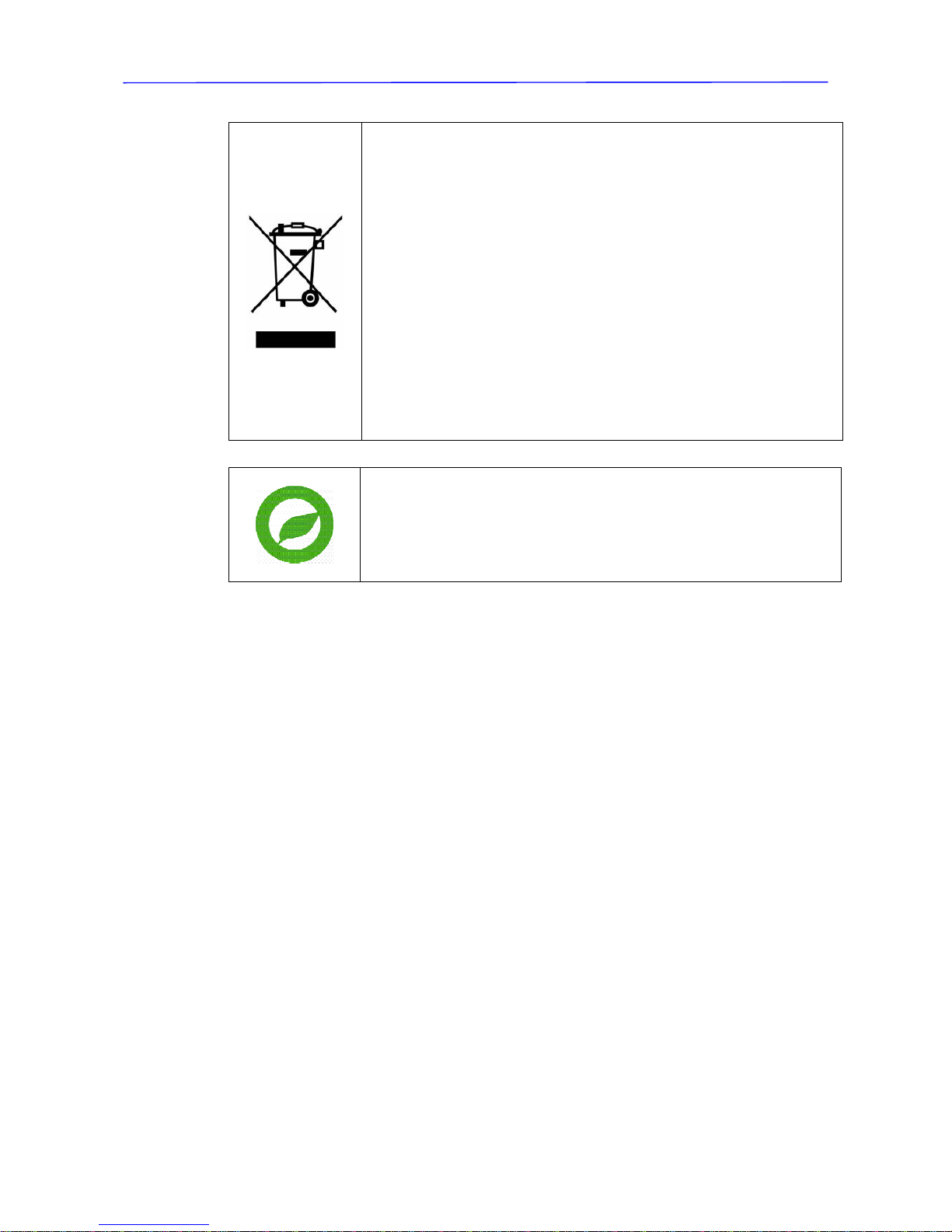
This symbol on the product or on its packaging indicates
that this product shall not be treated as household waste in
accordance with Directive 2002/96/EC. Instead it shall be
handed over to the applicable collection point for the
recycling of electrical and electronic equipment. By proper
waste handling of this product you ensure that it has no
negative consequences for the environment and human
health, which could otherwise be caused if this product is
thrown into the garbage bin. The recycling of materials will
help to conserve natural resources.
For more details information about recycling of this product,
please contact your local city office, your household waste
disposal service or the shop where you purchased the
product.
Compliance is evidenced by written declaration from our
suppliers, assuring that any potential trace contamination
levels of restricted substances are below the maximum
level set by EU Directive 2002/95/EC, or are exempted due
to their application.

Installation Guide
iii
Warnings and Cautions
• Handle the camera carefully
Do not abuse the camera. Avoid striking, shaking, etc. The camera could
be damaged by improper handing or storage.
• Installing electricity wiring carefully
Ask qualified personnel of electrical wiring for the installation. Please note
that input electricity to the unit is at tolerance of DC 12V/AC 24V ± 10%.
The camera is capable of surge protection; ensure AC power model unit
grounded appropriately against damage of heavy current or electric
shock.
• Do not disassemble the camera
To prevent electric shock, do not remove screws or covers. There are no
user serviceable parts inside. Ask a qualified service person for servicing.
• Do not block cooling holes on the bracket
This camera has a cooling fan inside. Blocking the cooling holes leads to
build up of heat the camera and may cause malfunction.
• Do not operate the camera beyond the specified temperature,
humidity or power source ratings
Use the camera under conditions where temperature is between -50°C ~
50°C (-58°F ~ 122°F), and relative humidity is belo w 90%.
• Do not use strong or abrasive detergents when cleaning the camera
body
Use a dry cloth to clean the camera when it is dirty. In case the dirt is hard
to remove, use a mild detergent and wipe the camera gently.
• Never face the camera towards the sun
Do not aim the camera at bright objects. Whether the camera is in use or
not, never aim it at the sun or other extremely bright objects. Otherwise,
the camera may be smeared or damaged.

Installation Guide
iv
Table of Contents
1. Introduction................................................................................................................1
2. Standard Package Contents .....................................................................................2
3. Camera Setups and Cable Connections..................................................................3
3.1 Preparations for Dome Camera Setups ......................................................................3
3.2 Dome Camera Setups................................................................................................5
3.2.1 Switch/Connector Definition .........................................................................5
3.3 Cables and Connections.............................................................................................6
3.3.1 Cable Requirements.....................................................................................6
3.3.2 22-Pin Data Cable........................................................................................6
3.3.3 22-Pin Connector Definition..........................................................................7
Network Model.............................................................................................7
3.3.5 Cable Wiring and Connection.......................................................................8
3.3.6 Ethernet Cable Connection..........................................................................9
4. Dome Camera Installation.......................................................................................10
4.1 Camera Dimensions.................................................................................................10
4.2 Optional Accessories ................................................................................................ 11
4.3 Ceiling Mounting with Straight Tube..........................................................................17
4.4 Wall Mount................................................................................................................ 19
4.4.1 Swan Tube.................................................................................................19
4.4.2 Compact Pendent Mount............................................................................20
4.4.3 Standard Pendent Mount............................................................................22
4.4.4 Wall Box Mounting .....................................................................................24
4.5 Corner Mount............................................................................................................ 26
4.5.1 Corner Standard Mounting Plate/Corner Plate Mini....................................26
4.5.2 Corner Thin/Wide Box Mounting.................................................................28
4.6 Pole Mount ...............................................................................................................30
4.6.1 Pole Thin/Wide Direct Mounting................................................................. 30
4.6.2 Pole Thin/Wide Box Mounting ....................................................................32
5. System Expansion...................................................................................................34
5.1 Connecting with Power Box...................................................................................... 34
Appendix A: Technical Specification .............................................................................35

Installation Guide
1
1. Introduction
With weather resistant feature, the Integrated High Speed Dome Camera is
applicable to outdoor installation. The network Speed Dome Camera
transmits digital video and audio data using wire connection. Live video can
be monitored and recorded from window-based computer via network.
The video encoder supports real-time Main Profile H.264 D1 resolution which
compresses the image size up to 40% off. Simultaneous dual streams,
H.264/H.264 and H.264/MJPEG, are available for various network
applications via speeding or limited bandwidth. Better image quality and high
resolution are delivered by IP support. Additionally, 3D de-interlaced
technology provides superior image quality. It eliminates the “combing” effect
due to scene change and performs more stabilized image.
With IP solution, multiple and authorized users can view the immediate image
from any location through network even using a standard web-browser. It
enables users to access and remote the camera without at specific locations.
Installation Guide
2
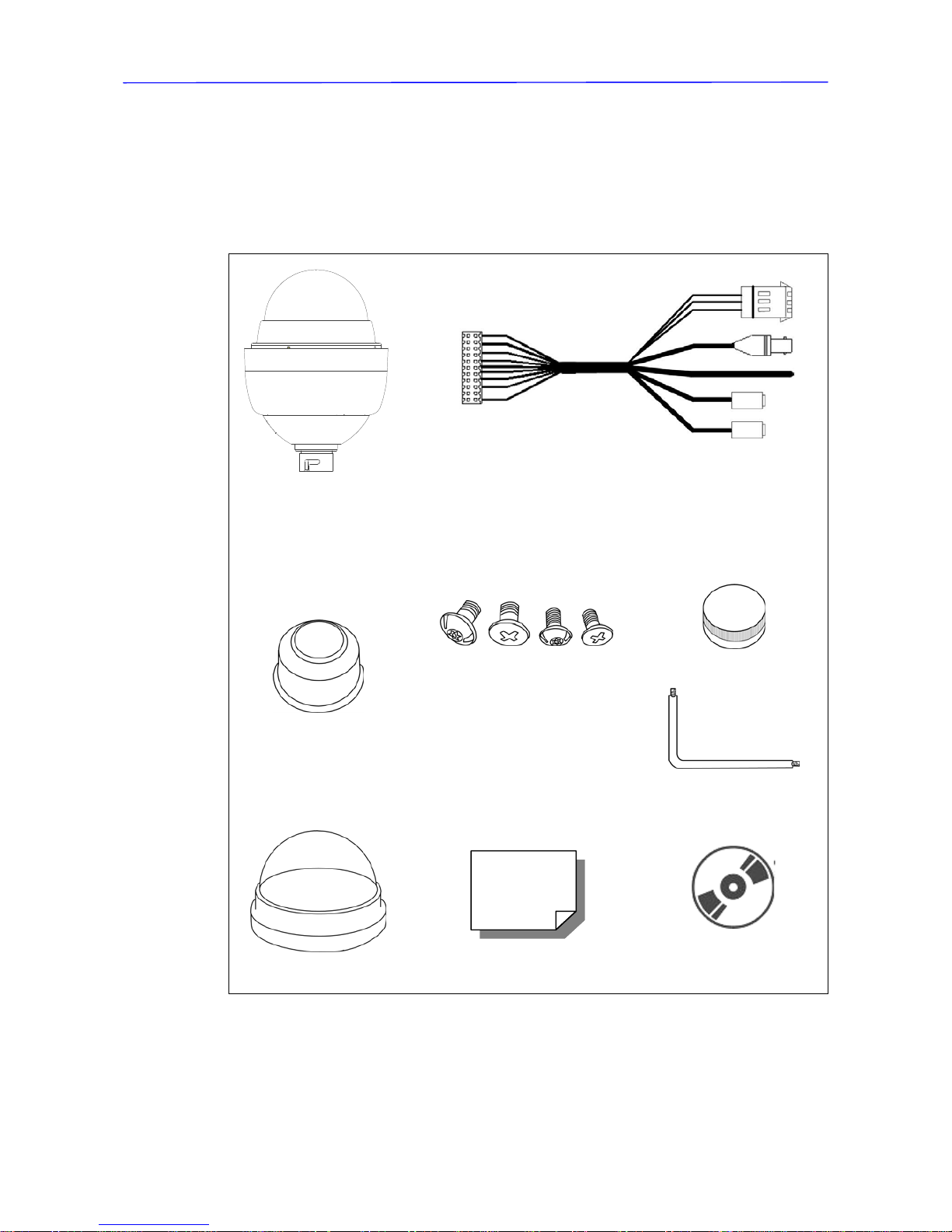
2. Standard Package Contents
Before proceeding, please check the box contains the items listed here. If any
item is missing or has defects, DO NOT install or operate the product and
contact your dealer for assistance.
Dome Camera with
Outdoor Mount Kit
Data Cable for Power Supply, Video, Audio and Alarm
(AC 24V)
Lubricant
Waterproof Rubber
M3 Standard Screw (x1)
M3 Security Screw (x1)
M5 Standard Screw (x1)
M5 Security Screw (x1)
Security Torx
Optical Cover
Quick Guide
CD: Operation Manuals
Installation Guide
3
3. Camera Setups and Cable Connections
Before installing or connecting the Dome Camera, please refer to this section
and complete preparations for Dome Camera setups and various switch
settings.
3.1 Preparations for Dome Camera Setups
The following installation procedure is for the outdoor Dome Camera that is
supplied with the sunshield housing. Please follow the steps below to
complete housing installation for the Dome Camera.
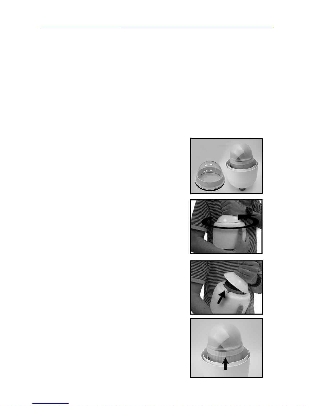
STEP 1
Unpack the Dome Camera’s package
and take out the Dome Camera unit.
STEP 2
Rotate the Outdoor Mount Kit, and take it
off from the camera body.
STEP 3
Remove the protective cover and PE
sheet.
Installation Guide
4
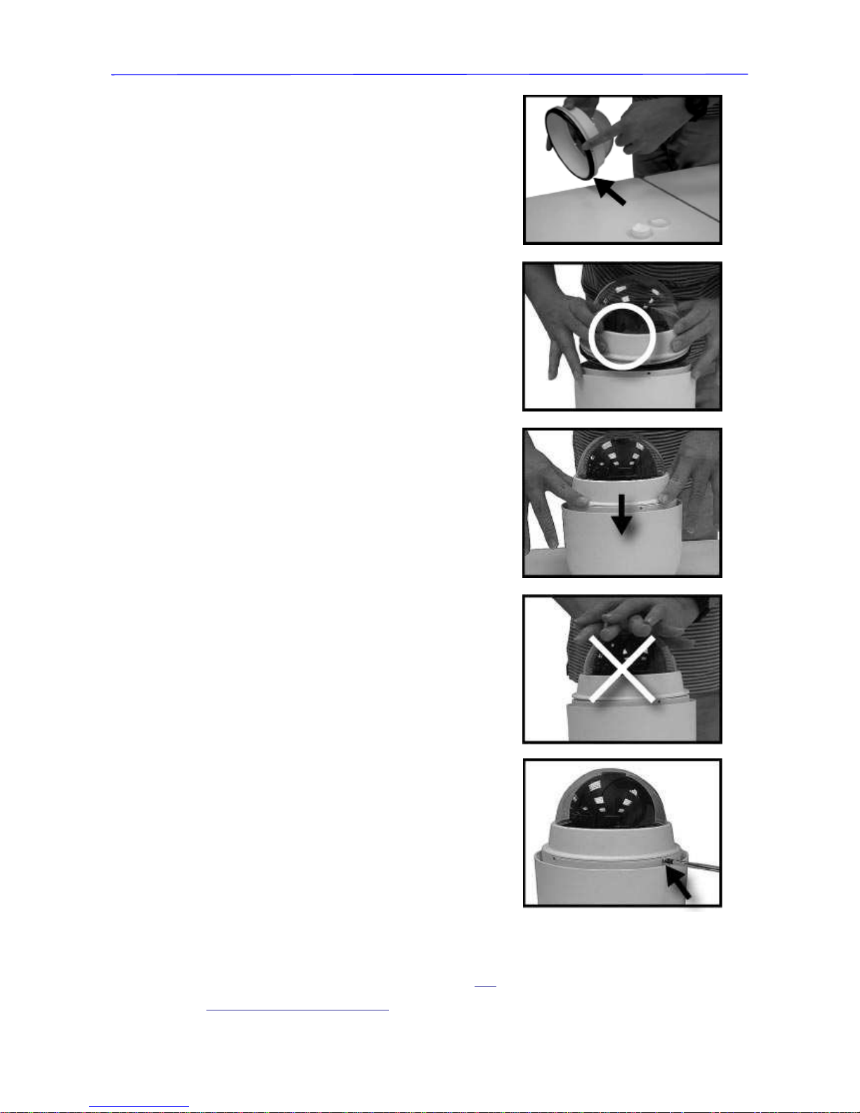
STEP 4
Attach the dome cover to the camera
body. Before doing that, apply some
lubricant on the cover’s water-proof
rubber to make the installation process
smoother.
Note that the tiny protrusion on the cover
must align with one of the four holes on
the camera body.
STEP 5
Gently press down the dome cover with
two hands on the side of it.
DO NOT press the cover, as shown in the
figure; this might cause damage to the
Dome Camera.
STEP 6
Screw the dome cover and camera body
together.
STEP 7
Set the switches located on the bottom of
the Dome Camera. Refer to section 3.2
Dome Camera Setups for detailed
information about various switch setting.
Installation Guide
5
3.2 Dome Camera Setups
Before connecting the Dome Camera to other devices of CCTV system,
please complete the Dome Camera’s ID and communication switch settings.
These switches are located on the bottom of the Dome Camera.
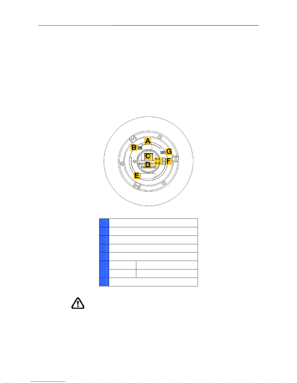
3.2.1 Switch/Connector Definition
Please refer to the diagrams and tables accompanied with for use of each
switch/connector.
A
None
B
Communication Switch (Reserved)
C
RJ-45 Connector
D
22-Pin Connector
E
None
F-1 Reboot Button
F
F-2 Factory Reset Button
G
ISP Connector (for FW upgrade)
NOTE: DO NOT change the network Speed Dome Camera’s
Communication Switch factory default settings.
Installation Guide
6
3.3 Cables and Connections
The Dome Camera is supplied with one integrated 22-pin Data Cable for
connecting with the power, video, and RS-485/audio input & audio output
cables. Please read the following sections thoroughly before making
connections.
3.3.1 Cable Requirements
For operation, the Integrated High Speed Dome Cameras require video and
power cables as described below:
• The video cable sends video signals to a remote viewing site. Using a
coaxial cable to send video signals is recommended.
• Power supply: DC 12V/AC 24V output voltage
NOTE: Ensure power supply meets the Dome Camera’s power
requirement, or product impairment will occur. If any mistake happens,
please contact with a qualified maintenance engineer.
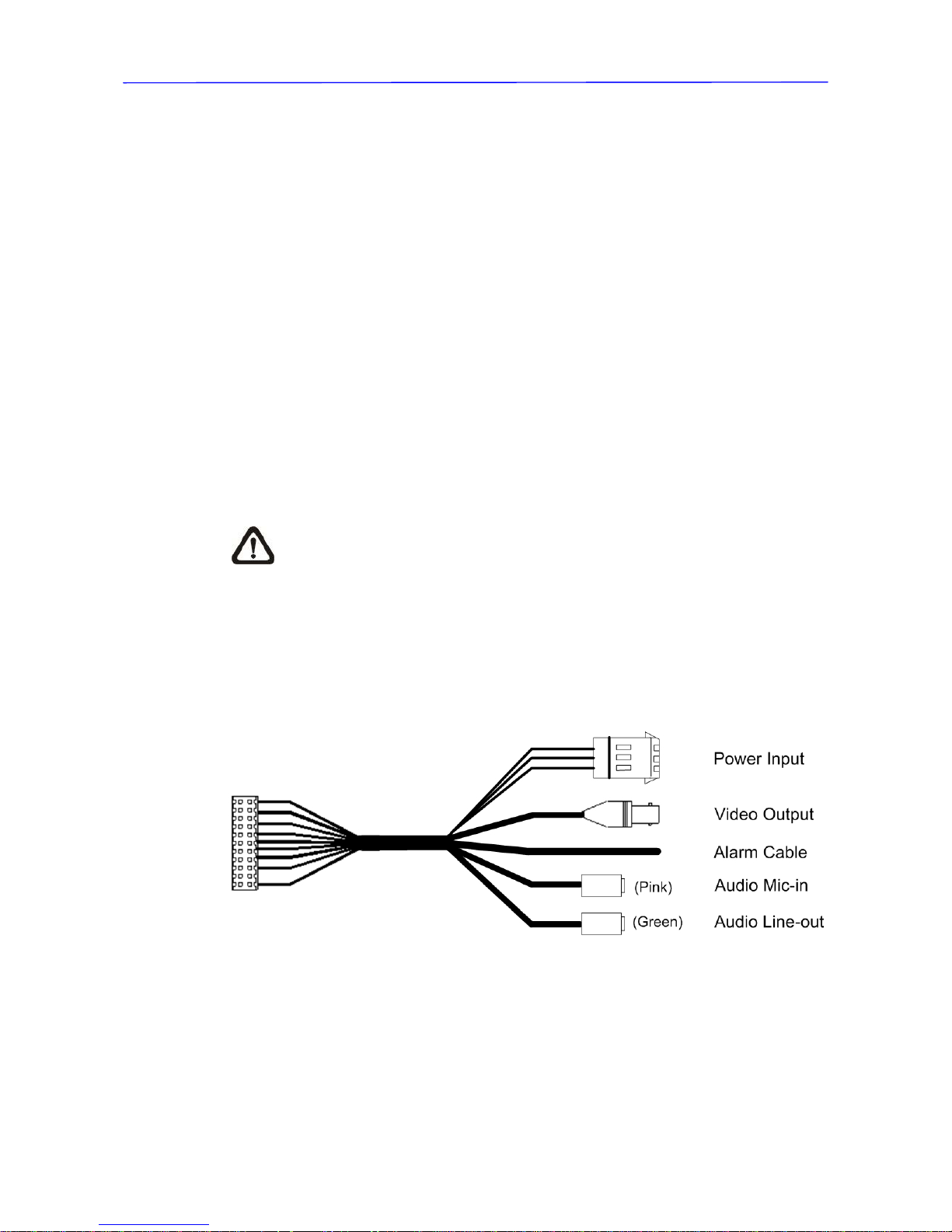
3.3.2 22-Pin Data Cable
The network Speed Dome Camera’s Data Cable is illustrated as follows.
Installation Guide
7
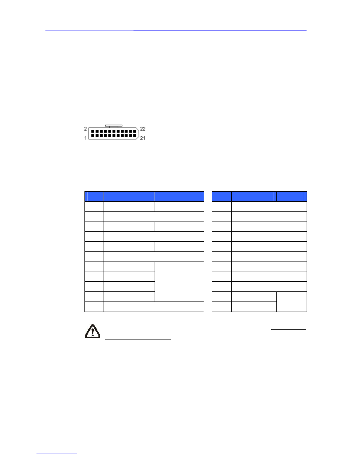
3.3.3 22-Pin Connector Definition
With the 22-pin connector, installers can simply connect the power, video and
RS-485 cables to the Dome Camera at once. Particularly, the alarm pins are
serviceable for connecting alarm input and output devices, such as alarm
sensors, sirens or flashing lights with the surveillance system. The analog and
network Speed Dome Cameras’ 22-pin connector definition will also be
specified as follows.
Network Model
The network Speed Dome Camera’s 22-pin connector definition is listed as
follows:
Pin
Definition Cable
Pin Definition Cable
1
AC 24-1/DC ()
20AWG/18AWG
12
ALM-1
2
ALM NC
13
ALM-3
3
AC 24-2/DC ()
20AWG/18AWG
14
ALM-2
4
ALM NO
15
ALM-4
5
FG 20AWG/18AWG
16
Reserved
6
ALM COM
17
Reserved
7
Audio in
18
Reserved
8
Audio out
19
Reserved
9
Audio GND
20
ALM GND
10
Audio GND
24AWG
21
VGND
11
ISOG
22
Video
20AWG
NOTE: For alarm connection, please refer to section 3.3.5 Cable
Wiring and Connection.
 Loading...