

Ganz ZN-L7210PHA, ZN-L7210NHA, ZN-L7000 Instruction Manual
ETHERNET CAMERA, MPEG-4
ZN-L7000
INSTRUCTION MANUAL
ZN-L7210PHA
ZN-L7210NHA
Colour high resolution camera with computar autoiris varifocal
lens, MPEG-4
1

Copyright This manual is the intellectual property of CBC (EUROPE) Ltd.. All
rights are reserved. No part of this document may be reproduced or
transmitted for any purpose, by whatever means, be they electronic or
mechanical, without the express written permission of CBC
(EUROPE) Ltd.
Edition: October 2003 (version 6.10)
Note This manual was compiled with the greatest of care and all
information double checked. At the time of printing the description was
complete and correct. Because of the further development of the
products, the content of the manual might change without prior notice.
CBC (EUROPE) Ltd. will not be liable for damage which is directly due
to errors, incompleteness or discrepancies between the manual and
the product described.
Trade Marks All names used in this manual for hardware and software are very
probably registered trade marks and must be treated as such.
This is a class A product. In a domestic enviroment, this product
may cause radio interference in which case the user maybe
required to take adequate measures.
ENG-
2

INDEX
INDEX
INTRODUCTION
SAFETY INFORMATIONS
PRODUCT DESCRIPTION
INSTALLATION
CONFIGURATION WITH WEB BROWSER
OPERATION WITH INTERNET EXPLORER
SERVICE
TECHNICAL SPECIFICATIONS
3
4
5
6
9
12
27
29
30
ENG-
3

INTRODUCTION
This manual is intended for persons authorized to install and operate of this camera and
VCS products .International, national and any relevant regional regulations relating to
electronics must be observed at all times.
Conventions
In this manual, the following symbols and notations are used to draw attention to special
situations:
Attention! This symbol indicates tips and notes that make using the device
easier and more convenient.
Hazard! This symbol indicates that failure to follow the safety instructions
given may directly endanger people, cause damage to the system or to other
equipment. This symbol represents a direct threat of danger.
The following typographic conventions are used in this manual:
Configuration menu names and window and key names and parameters
[Enter],[C] key names
[Ctrl]+[C] two or more keys that are pressed simultaneously
ping Command line input and output
Intended use
This camera serves to transmit video and control signals via data networks (Ethernet LAN).
This camera is designed for use in CCTV systems. The connection of an external alarm
generator allows functions to be triggered automatically. Other applications are not
permitted.
In the event of questions concerning the use of the devices which are not answered in this
manual, please contact your dealer.
This camera is compatible with following VCS products: VideoJet10e, VideoJet100e,
VideoJet1000 and Vidos softwares.
ENG-
4

SAFETY INFORMATIONS
Electrical shock hazard
¾ Never attempt to connect the unit or the mains power supply to any power network
other than the one for which it was
¾ Use only appropriate and approved power supply units for the camera (see
technical specifications)
¾ Do not open the housing of the power supply unit
¾ Disconnect the power supply unit from the mains power supply and from all other
devices if fault occurs
¾ Install the power supply unit and the unit only in a dry place protected against the
elements
¾ If you are uncertain about the safe operation of the unit, shut it down immediately
and secure it to prevent any unauthorized start-up. Safe is no longer possible, for
example:
If damage is visible to the unit or the cables
If the unit no longer operates correctly
If the unit has been exposed to rain or moisture
If objects have penetrated inside the unit
After long storage under improper conditions or
After heavy demands during transport
Installation and operation
¾ All applicable electrical codes and regulations must be observed and followed at all
times during the installation.
¾ Before installing or operating the system, ensure that you have read and
understood the documentation for other equipment connected to the unit, e.g.
monitors or pan-tilt heads. These contain important safety notices and information
concerning permissible applications.
¾ Perform only installation and operating work described in this manual. All other
work beyond this may lead to injuries to persons and damage to the system or
other equipment.
¾ Ensure a secure footing whenever working in elevated positions. Use only safety
ladders. If necessary, use safety harness or railings.
¾ Use this camera with original Ganz tools.
Repairs and maintenance
¾ Never open the housing of the unit.
¾ Never open the housing of the power supply unit.
¾ Ensure that only qualified, specialist personnel are permitted to carry out
maintenance or repair work.
¾ Contact your dealer for authorized reparation.
ENG-
5

PRODUCT DESCRIPTION
Preconditions for commissioning
¾ Computer with operating system Windows 98/2000/XP and gateway to the network
¾ Microsoft Internet Explorer web browser (from version 5) or free serial interface and
terminal program
Preconditions for configuration
¾ Computer with operating system Windows 98/2000/XP and gateway to the network
¾ Microsoft Internet Explorer (from version 5) and MPEG-ActiveX
Preconditions for operating
¾ Computer with operating system Windows 98/2000/XP and gateway to the network
¾ Microsoft Internet Explorer (version 5) and MPEG-ActiveX
¾ VideoJet10e / VideoJet100e with PAL/NTSC monitor or software VIDOS
Functions
This device is a high-resolution colour camera for professional use in CCTV system. It has
an integral video server for encoding of the video and control signals for the transfer via an
Ethernet LAN.
The camera ¼” CCD offers a horizontal resolution of 480TVL(PAL)/470TVL(NTSC). The
camera is characterized by a 4X computar varifocal lens, automatic DC.
All the camera parameters are conveniently set via HTML pages using an internet browser,
except flickerless function, BLC and iris setup.
Main functions are:
¾ Automatic DC iris and varifocal lens
¾ BLC and flickerless
¾ Picture saturation regulation
¾ Analog video output PAL/NTSC (BNC) for focus and iris setup
ENG-
6

Multicast functions
This camera supports the standard MPEG-4. Thanks to efficient encoding, the data
transmission rate remains low, even with maximum image quality and 25 images/s;
furthermore, it can be adapted over a wide range to meet the local requirements.
In appropriately configured networks, the multicast function permits the simultaneous video
transmission in real time to several receivers. A precondition for this is the implementation
of the UDP and IGMP protocols in the network.
Remote control
For remote control of external equipment, the control data is transmitted via the
bidirectional serial interface of the unit. This interface can also be used for the
transmission of transparent data.
Configuration
This camera can be configured with a browser via the local network or via
Internet. Firmware updates and the quick uploading of device configurations
are possible in the same way. Please consider that disconnecting the
camera or power supply loss during the firmware update function can
seriously damage the camera.
Recording and playback
You can save live pictures recorded by the unit as files on the hard disk of your computer.
The video pictures are stored in MPEG-4 format and can, for example, be replayed with
MPEG Player included in delivery.
The RAM memory integrated in the unit serves as pre-alarm memory. On this ring buffer
video pictures are recorded as long as there is no active connection to a receiver unit
(duration ~19 secs.).
Summary
¾ Video and data transmission via data networks
¾ Digitally optimized video data
¾ Automatic iris control
¾ 4X Varifocal lens
¾ Multicast or video streaming multicast connection
¾ Locale analog (PAL) video output
¾ 25 FPS (high res.)
¾ MPEG-4 or M-JPEG
¾ Integral Ethernet interface 10Base-T
¾ Transparent bidirectional data channel via serial interface RS232 RS485/422
¾ Remote control of internal functions via TCP and UDP
¾ 3-steps password protection
¾ Alarm input (NO or NC)
¾ Relay (NO or NC)
¾ Automatic connection on alarm
¾ Integrated activity detector
¾ email on alarm
¾ Firmware upgrade by flash memory
ENG-
7
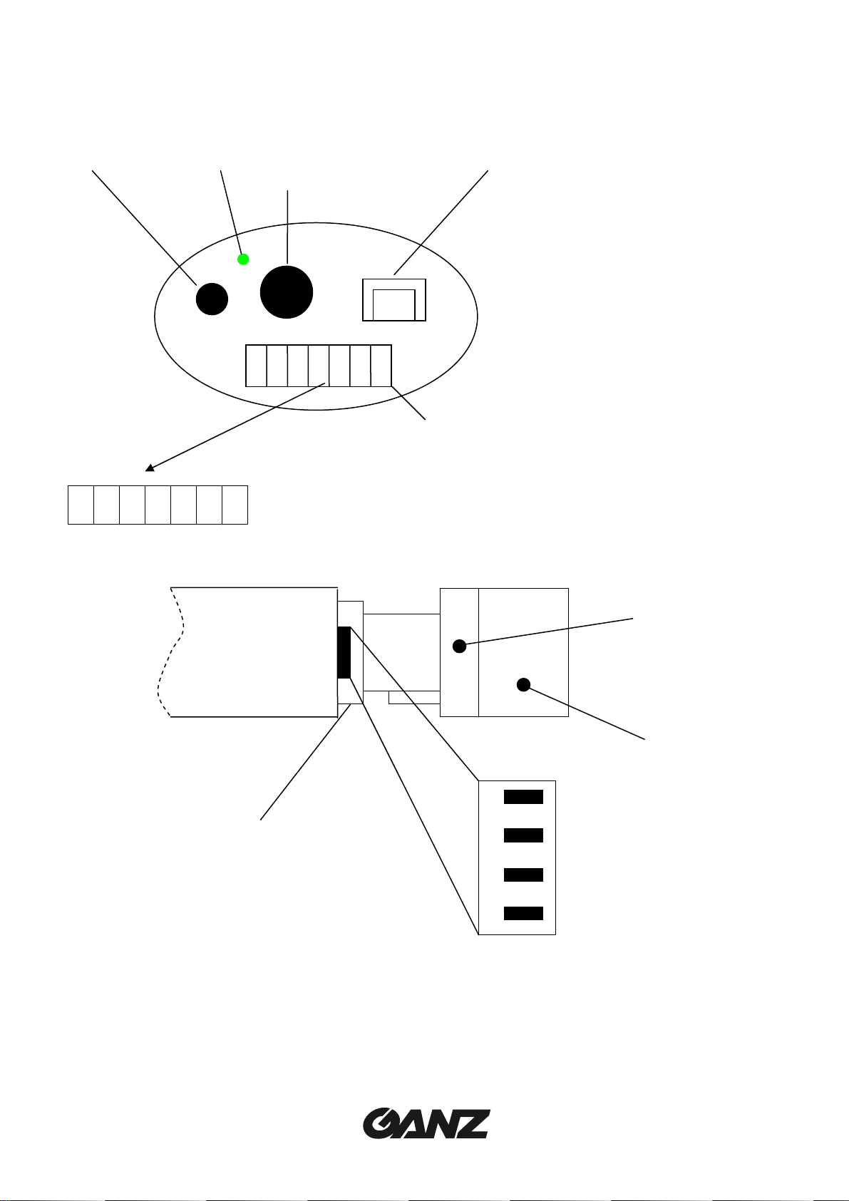
Connectors and Controls
1 2 4
3
1 2 3 4 5 6 7
4 12VDC
5 GND
6 Alarm input (NO/NC)
7 Alarm input GND
5 / 8
1 DC iris: ON
2 Flickerless: ON/OFF
3 BLC: ON/OFF
4 Always ON
1 Serial port RS232/RS485/422
2 Power led
3 Local analog video output (BNC)
4 Ethernet 10Base-T
5 Power, alarm, relay
1 Relay COM
2 Relay NO (closed when camera off)
3 Relay NC (opened when camera off)
6
7
1
2
3
4
5 VR for iris adjustment
6 Zoom adjustment
7 Focus adjustment
8 DC iris connector
ENG-
8

INSTALLATION
The camera is designed for indoor operations. Choose a site for installation which
ensures that camera is exposed to neither extreme temperatures nor extreme
moisture or humidity. The ambient temperature must lie between +5 and +40°C,
the relative humidity must not exceed 80%.
During operation, the unit generates a great deal of heat. Therefore ensure
sufficient ventilation and an adequate distance to heat-sensitive equipment or
objects.
Please observe the following installation conditions:
¾ Do not install the camera in the immediate vicinity of radiators or other sources of heat.
Avoid installing the camera where it is exposed to direct sunlight.
¾ Ensure sufficient space for laying the cables.
¾ Ensure adequate ventilation of the camera.
¾ For all cable connections, use only the suitable cables which also prevent any electrical
interference, where necessary.
¾ Ensure that the camera is not exposed to water at the installation site. If necessary, use
fresh desiccant in waterproof housing to avoid moisture due to condensation.
¾ Lay and install all cables in such a way that they cannot be damaged and ensure
sufficient strain relief.
¾ The installation always depends on the actual situation. No concrete instructions can
therefore be given here. The camera has a standard ¼” thread which can be installed
on both the top and bottom of the housing.
¾ Lay all cables up to the installation position.
¾ If necessary, connect a monitor with a coax cable (75 Ohm) to the BNC jack in order to
be able to check the video image on the spot.
¾ Connect the leads of the power supply unit to terminals + and – of the DC 12V
CONNECTOR. Pay attention to the correct connection of the leads.
Network connection
You can connect the camera via hub to a 10Base-T network. Use a standard UTP Category 5
with RJ45 connectors.
ENG-
9
Alarm input, relay output
The alarm input of the camera serves for the connection of an external alarm trigger. If
configured accordingly, an alarm trigger can, for example, set up an automatic connection
between the camera and a remote station.
The relay output serves for switching external devices. This control output can be used
interactively during an active connection with the camera. The contact can be programmed as
NO or NC and it is possible to invert the mechanical function by software setup. However, the
NC terminal will open if the camera is powered down and the NO will close. In this way the
camera is able to show also a power loss failure.
The relay contact must not be subjected to a burden of more that 30 V and 1A.
Serial port
The serial port is commonly used to drive connected pan-tilt devices.
Read carefully the related manuals before to connect them to the camera.
Uncorrected use of serial port can damage the camera.
Pin layout:
Pin RS232 RS485/422
1 RX RX+
2 TX TX3 RTS TX+
4 CTS RX5 GND GND
1 2
3 4
5 6
Power supply
This camera has no mains power switch. When you have connected the power supply unit to
the device and inserted the power unit plug into a mains socket, the device is ready for
operation.
Connector soldering side
ENG-
10
 Loading...