

Ganz ZN-D212XE Installation Manual
IPN2102HD-5511
Installation Guide
INFORMATION TO USER
CAUTION
RISK OF ELECTRIC SHOCK,
DO NOT OPEN
!
CAUTION: TO REDUCE THE RISK OF ELECTRIC SHOCK,
DO NOT REMOVE COVER (OR BACK).
CONTACT QUALIFIED SERVICE PERSONNEL FOR INTERNAL PARTS.
This symbol is intended to alert the user the presence of un-insulated
“dangerous voltage” within the product’s enclosure, which may be sufficient
magnitude to constitute a electric shock risk to persons.
!
This symbol is intended to alert the user the presence of important operating
and maintenance (servicing) instructions within the guide manual.

ZN-D212XE installation Guide
01A.01 3
Table of Contents
1. FEATURES ................................................................................................................. 4
2. PACKAGE CONTENTS ................................................................................................ 5
3. PART NAMES ............................................................................................................ 6
4. INSTALLATION .......................................................................................................... 7
4.1. Option A. Semi-Flush Mount ........................................................................................... 7
4.2. Option B. Flush Mount ................................................................................................... 9
4.3. Setting the Image Attribute .......................................................................................... 11
5. CONNECTIONS ........................................................................................................ 12
6. CONFIGURATION .................................................................................................... 15
6.1.Set up network environment ......................................................................................... 15
6.1.1. Generic IP Environment ......................................................................................... 15
6.1.2. Custom IP Environment ......................................................................................... 16
6.2. View video on web page ............................................................................................... 17
6.2.1. View video using IPAdmin Tool .............................................................................. 18
6.3. Reset ............................................................................................................................ 19
6.4. Factory Default ............................................................................................................. 19
APPENDIX (A): SPECIFICATIONS.................................................................................. 20
Summary ............................................................................................................................ 20
Electrical Characteristics ..................................................................................................... 21
Environment Condition ....................................................................................................... 21
Mechanical Condition ......................................................................................................... 21
APPENDIX (B): POWER OVER ETHERNET .................................................................... 22
PoE compatibility ................................................................................................................ 22
Power classification............................................................................................................. 22
APPENDIX (C): DIMENSIONS ....................................................................................... 23
APPENDIX (D): HEXADECIMAL-DECIMAL CONVERSION TABLE ................................... 24
REVISION HISTORY ..................................................................................................... 26

ZN-D212XE installation Guide
01A.01 4
1. FEATURES
Camera
Full HD indoor fisheye IP camera (Vandal proof)
High quality compression in real time streaming
1/2.7” 1080p CMOS Image Sensor
180˚ wide and 160˚ vertical angle
Remote Zoom/Focus Control(One Click AF)
Streaming
Dual streaming mode
De-interlacing on DSP
Burnt-in text supported
Unicast/Multicast supported
Video/Audio
Video compression: H.264/MJPEG, 25/30FPS@1080p(PAL/NTSC)
Audio compression: G.711(µLaw, aLaw)/PCM
Analog video out for external monitors
Video motion detection supported
Two-way mono audio supported
Network
RTSP/ HTTP protocol supported
10/100 Base-T Ethernet
Additional Features
Micro SD card support
PoE support
Built-in Video Content Analysis
SDK (Software Development Kit) provided
ZN-D212XE installation Guide
01A.01 5
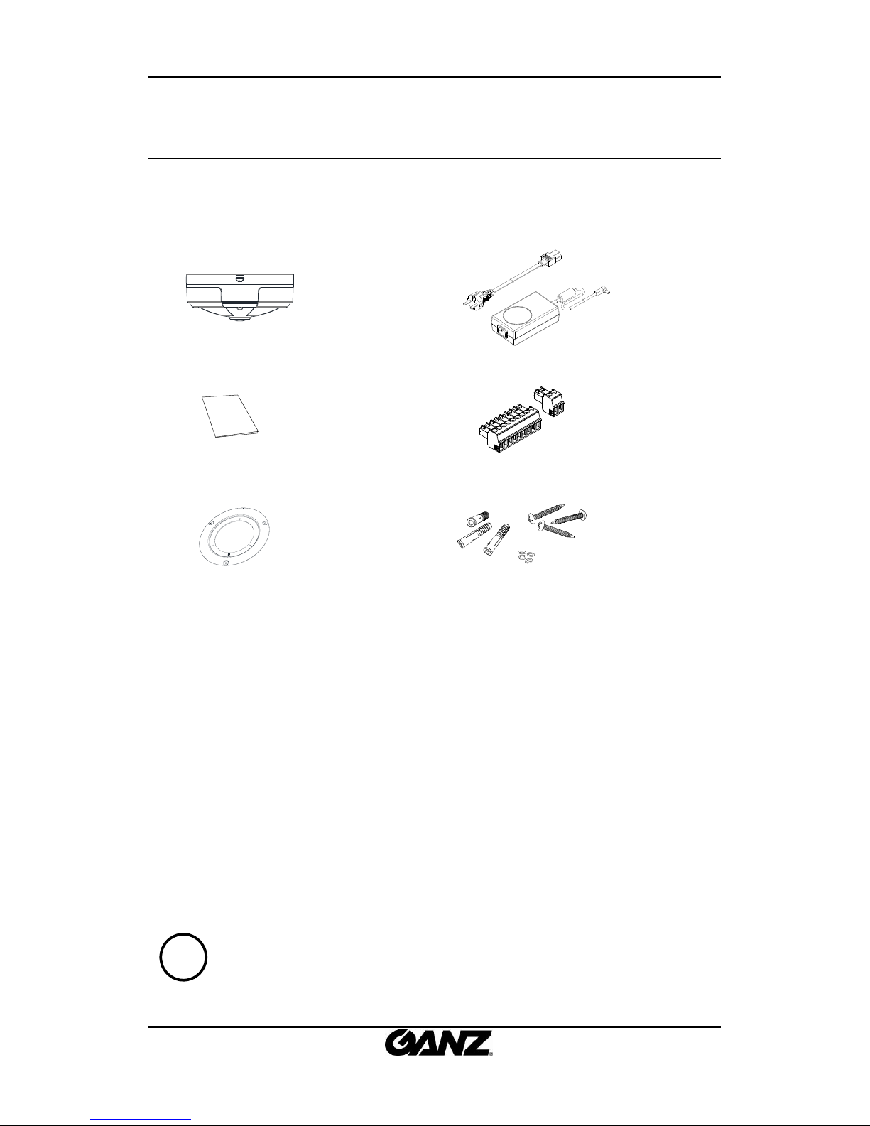
2. PACKAGE CONTENTS
Unpack carefully and handle the equipment with care. The packaging contains:
Camera
DC power adapter
Quick installation guide
9-pin and 2-pin terminal blocks
FMB mount (for flush mount)
Screws and anchors
Note
i
The above contents are subject to change without prior notice.
ZN-D212XE installation Guide
01A.01 6
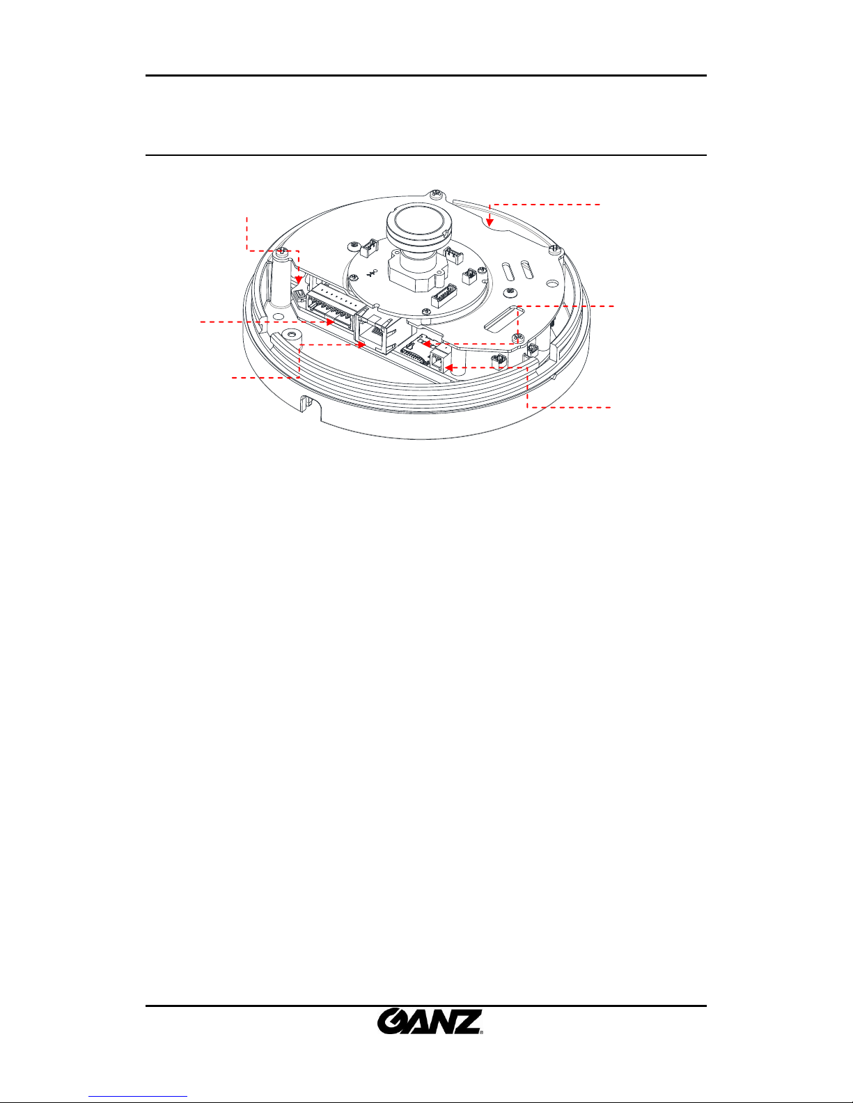
3. PART NAMES
① Rest button
The reset button can be used for restarting the device or resetting it to Factory Default.
② PAL/NTSC button
Pressing the button cycles through PAL, NTSC, and no video output mode: No video output -> PAL->NTSC
③ Video, Audio, and IO terminal connector
Connector for cable connection of audio input/output and digital input/output .
④ LAN connector
RJ45 LAN connector for 10/100 Base-T Ethernet.
⑤ MicroSD Slot
Slot for the MicroSD card
⑥ Power Adapter Connector
DC 12V adapter for power supply.
②
③
⑤
⑥
* Models and their appearance are subject to change without any prior notice.
④
①
*This button is located under PCB.
ZN-D212XE installation Guide
01A.01 7
4. INSTALLATION
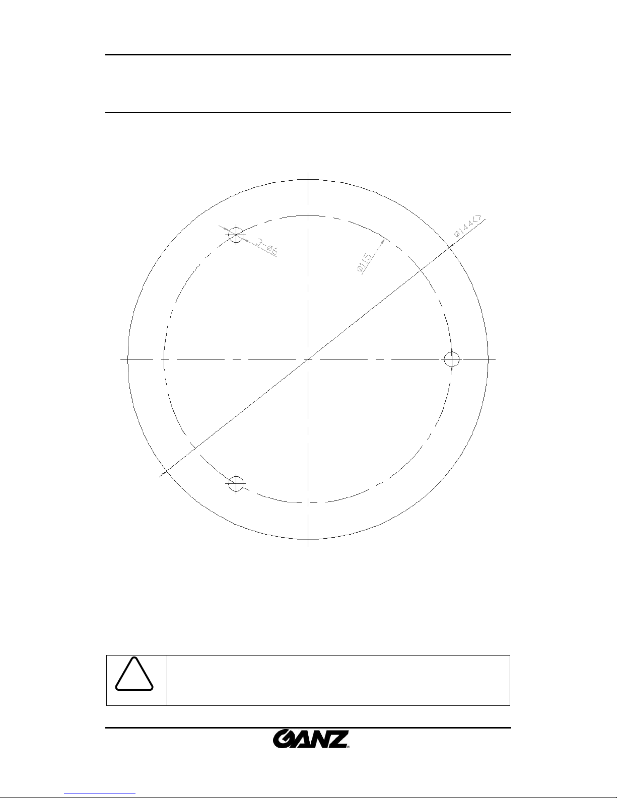
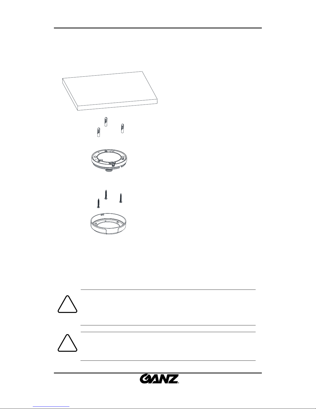
4.1. Option A. Semi-Flush Mount
Caution
!
Installation template image’s size scale in this installation guide is not 1:1.
The correct-size template design paper can be found inside the package separ
ately.
ZN-D212XE installation Guide
01A.01 8
1) Place the installation template on a
surface where camera is going to be
installed and mark the anchor block
placements.
2) Drill and insert anchor blocks on a
marked surface.
3) Mount the main camera body by
aligning the anchor blocks and hold against
the mounting surface..
4) Tighten the anchor blocks with screws
5) Connect all the appropriate cables to
the device
6) Attach the dome cover on main body
and lock it up by rotating.
Caution
!
When placing the dome cover, look for carved triangle mark on both dome cov
er and main body. Both triangles should be aligned together when placing the c
over. Once the cover has been placed, rotate the dome cover for a secure lock.
To detach the cover, rotate the dome cover and align two triangle marks, and
pull the cover.
Caution
!
To prevent products from damaging, place the camera on stable and non-vibrat
ing surfaces. If the stability is in doubt, consult with safety personnel for reinfor
cements, and then proceed with the installation.
 Loading...