


PixelPro GXi IPX/IPN Series ZN1-V4FN3/FN4IPN8102 Installation Guide
ZN1-V4FN3, ZN1-V4FN4
04-2014-A i

PixelPro GXi Series ZN1-V4FN3/FN4 Installation Guide
Precaution
Please read this manual carefully before installing the units.
Never disassemble the main unit and the camera unit. Unauthorized disassembly may
cause equipment failure or damage to the unit.
Do not install the product on unstable brackets, unstable or vibrating surfaces since
this could cause damage to the product.
Use only the accessories provided or recommended by the manufacturer.
Do not operate the camera in environments beyond the specified temperature. Refer
to “Environment Condition” on “APPENDIX(A): SPECIFICATIONS” in this manual.
Before applying power to the camera, check the power source to ensure that it is
within the specifications. Refer to “Electrical Characteristics” on “APPENDIX(A):
SPECIFICATIONS”.
06-2014-B 2

PixelPro GXi Series ZN1-V4FN3/FN4 Installation Guide
Safety Instruction
1) Read these instructions.
2) Keep these instructions.
3) Heed all warnings.
4) Follow all instructions.
5) Do not use this apparatus near water.
6) Clean only with a dry cloth.
7) Do not block any of the ventilation openings. Install in accordance with the
manufacturer's instructions.
8) Do not install near any heat sources such as radiators, heat registers, stoves, or
other apparatus that produce heat.
9) Only use the attachments/accessories specified by the manufacturer.
10) Use only with a cart, stand, tripod or bracket specified by the manufacturer, or sold
with the apparatus. When a cart is used, use caution when moving the
cart/apparatus combination to avoid injury from tip-over.
12) Unplug this apparatus during lightning storms or when unused for long periods of
time.
13) Refer all servicing to qualified service personnel. Servicing is required when the
apparatus has been damaged in any way, such as power supply cord or plug is
damaged, liquid has been spilled or objects have fallen into the apparatus, the
apparatus has been exposed to rain or moisture, does not operate normally, or
has been dropped.
14) WARNING: To reduce the risk of fire or electric shock, do not expose this
apparatus to rain or moisture. The apparatus shall not be exposed to dripping or
splashing and that no objects filled with liquids, such as vases, shall not be placed
on apparatus.
06-2014-B 3

PixelPro GXi Series ZN1-V4FN3/FN4 Installation Guide
Table of Contents
Precaution ........................................................................................................................... 2
Safety Instruction ................................................................................................................ 3
1. FEATURES ........................................................................................................................ 5
2. PACKAGE CONTENTS ........................................................................................................ 6
3. PART NAMES ................................................................................................................... 7
4. INSTALLATION ................................................................................................................. 9
4.1. Camera Unit Installation .................................................................................................... 9
4.2. Main Unit Installation ....................................................................................................... 13
4.3. Setting the Image Attribute ............................................................................................. 14
5. CONNECTIONS ............................................................................................................... 15
6. CONFIGURATION ........................................................................................................... 18
6.1. Set up network environment ........................................................................................... 18
6.1.1. Generic IP Environment ............................................................................................ 18
6.1.2. Custom IP Environment............................................................................................. 19
6.2. View video on web page .................................................................................................. 20
6.2.1. ActiveX Installation .................................................................................................... 20
6.2.2. View video using IPAdmin Tool ................................................................................. 21
6.3. Reset ................................................................................................................................. 22
6.4. Factory Default ................................................................................................................. 22
6.5. Safe Mode ........................................................................................................................ 23
APPENDIX (A): SPECIFICATIONS .......................................................................................... 25
Summary ................................................................................................................................. 25
Electrical Characteristics ......................................................................................................... 26
Environment Condition ........................................................................................................... 26
Mechanical Condition ............................................................................................................. 26
APPENDIX (B): POWER OVER ETHERNET ............................................................................. 27
Power Comparison .................................................................................................................. 27
APPENDIX (C): DIMENSIONS ............................................................................................... 28
APPENDIX (D): HEXADECIMAL-DECIMAL CONVERSION TABLE ............................................. 31
REVISION HISTORY ............................................................................................................ 35
06-2014-B 4

PixelPro GXi Series ZN1-V4FN3/FN4 Installation Guide
1. FEATURES
Camera
Pinhole camera
1/3” 1080p CMOS Image Sensor
Digital Day/Night
Digital WDR
Video
H.264 Baseline, Main, High profile(MPEG-4 Part 10/AVC), MJPEG(Motion JPEG)
Max 30fps in 1080p
Text Overlay
Network
10 / 100 Base-T Ethernet
Integration
Software Development Kit (SDK) available
ONVIF Compliant (Profile S)
General
microSD slot
Power Over Ethernet (PoE)
Video Contents Analysis (VCA)
VCA Presence (Standard)
VCA Surveillance (Optional)
06-2014-B 5
PixelPro GXi Series ZN1-V4FN3/FN4 Installation Guide
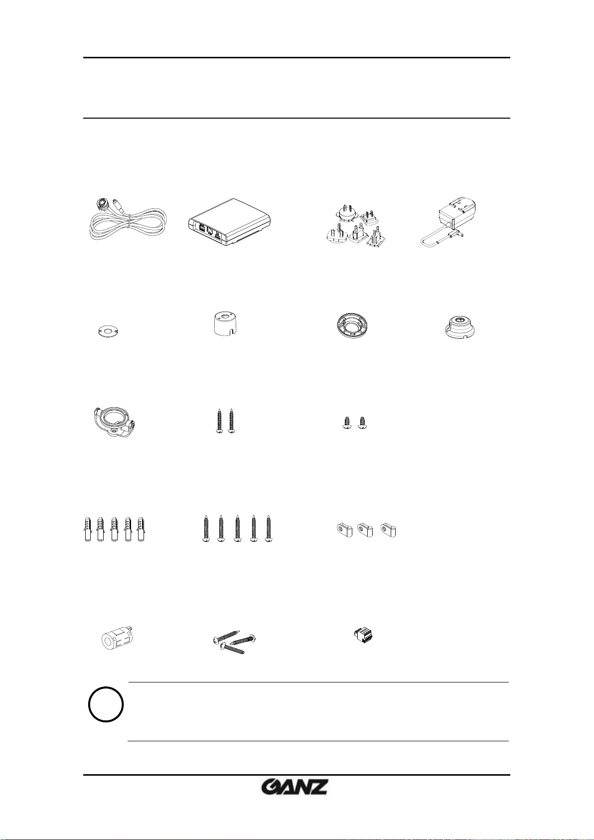
Camera Unit
Main Unit
Universal Plugs
Power Adaptor (12VDC)
Double-sided tape
for Covert Cover
Covert Cover
Rotate Ring
Surface Mount Bracket
PAN/TILT Bracket
Tapping Screws
(TP1 M3x20) x 2pcs
Screws
(TP2 M3x6(Ni)) x 2pcs
Anchor Blocks
(M4x25) x 5pcs
Tapping Screws
(TS1 M4x25) x 5pcs
Cable Clamps x 3 pcs
Ferrite Core
Tapping Screws
(TP1 M4x20) x 3pcs
4 Pin Terminal Block
Note
i
The contents above are subject to change without prior notice.
2. PACKAGE CONTENTS
Please unpack the package carefully and handle the equipment with care.
The package contains:
06-2014-B 6
PixelPro GXi Series ZN1-V4FN3/FN4 Installation Guide
* Model herein and its appearance are subject to change without any prior notice.
④
⑤
⑥
⑦
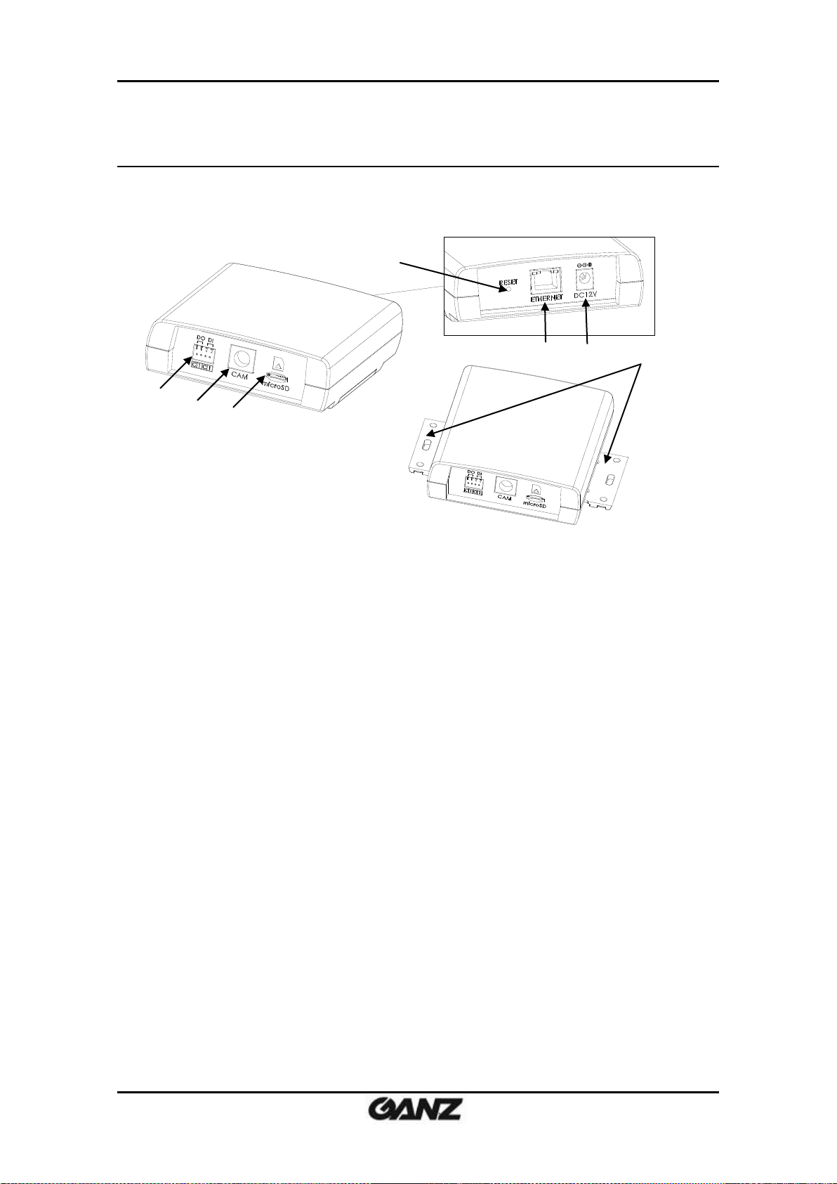
3. PART NAMES
Main Unit
① Terminal connector
Connector for cable connection for digital input / output. Refer to “5. CONNECTIONS”
for more details.
② Camera Connector
Connector for camera unit
③ microSD slot
Supports up to 64GB. Class 4 and higher SD card is recommended for HD recordings.
④ Reset button
This button will restart or reset to factory default settings. Refer to “6.3. Reset” and “6.4.
Factory Default” for more details.
⑤ LAN Connector
RJ45 LAN connector for 10/100 Base-T Ethernet (PoE supported)
⑥ Power Adaptor Connector
12VDC power supply connection
⑦ Slide Plate
Built-in mounting bracket for main unit
06-2014-B 7
PixelPro GXi Series ZN1-V4FN3/FN4 Installation Guide
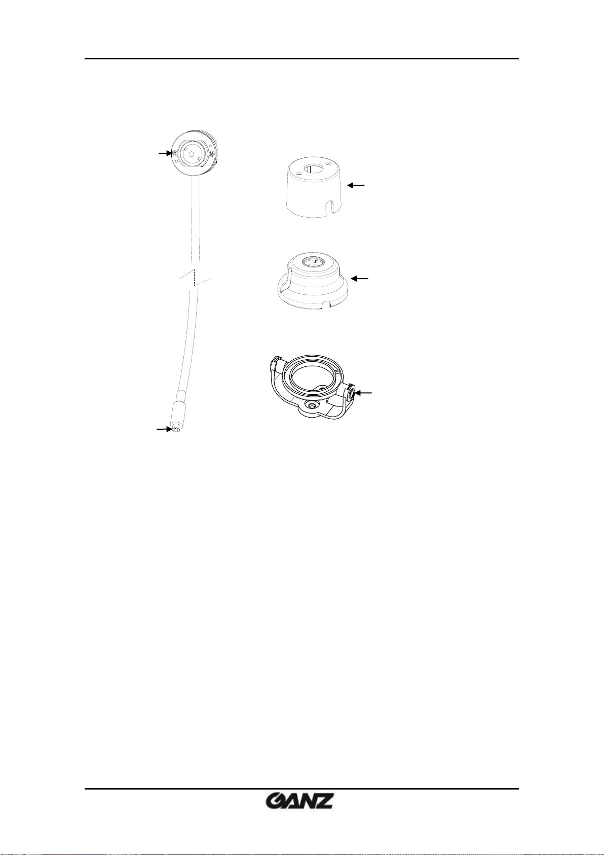
①
③
④
⑤
②
* Models herein and their appearance are subject to change without any prior notice.
Camera Unit with conjoined accessories
① Camera
Pinhole camera
② Camera DIN connector
Connector to be inserted to the camera connector on the main unit
③ Covert Cover
Bracket to be installed behind the wall or ceiling to hold the camera inside
④ Surface Mount Bracket
Bracket to be installed on the wall or ceiling to hold the camera inside
⑤ Pan/Tilt Bracket
Bracket to be installed on the wall or ceiling for camera’s angle adjustment
It shall be combined with the rotate ring and the surface mount bracket for the complete
installation.
06-2014-B 8

PixelPro GXi Series ZN1-V4FN3/FN4 Installation Guide
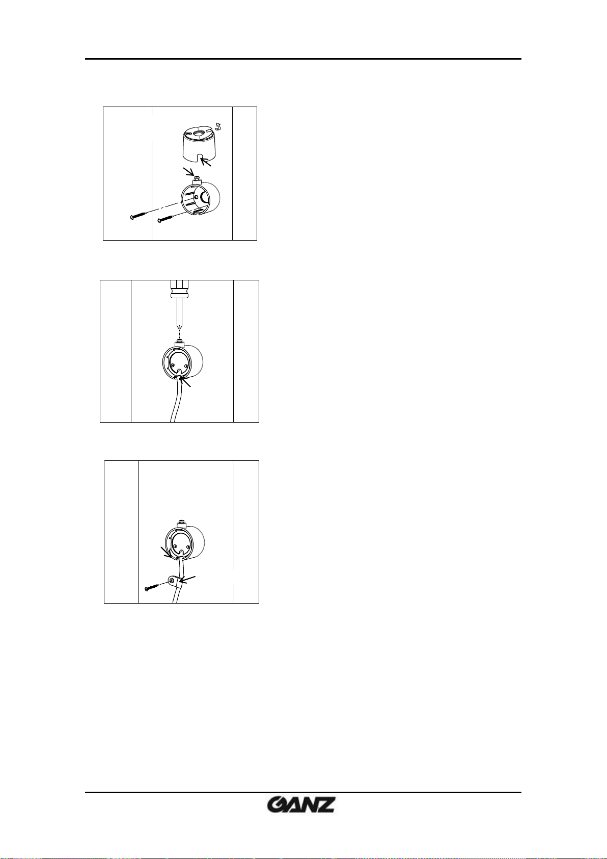
1) Drill a hole with 3mm diameters on a desired
spot where the camera lens will be located.
2) Peel off one side of the double-sided tape,
and attach it to the flat surface of the covert
cover by aligning the grooves on the tape
with the screw holes on the covert cover.
tape
groove
Screw hole
(Behind the wall or
above the ceiling)
4. INSTALLATION
The installation method of ZN1-V4FN3 and ZN1-V4FN4 is identical.
The installation method of the camera unit differs depending on your bracket type, but the
rest of the overall installation process is the same.
4.1. Camera Unit Installation
There are three different ways to install the camera unit:
- Covertly behind the wall or ceiling by using the covert cover
- Mounted and fixed on the wall or ceiling by using the surface mount bracket
- Mounted and fixed on the wall or ceiling by using the pan/tilt bracket to enable the
camera’s angle adjustment
Covert Installation
06-2014-B 9
PixelPro GXi Series ZN1-V4FN3/FN4 Installation Guide
3) Peel off the other side of the tape, and stick
the taped surface to the installation surface
by placing it with the screw head upward and
the cable holder downward and aligning it
with the drilled hole on the installation
surface.
5) Place the camera inside the covert cover by
routing the camera’s cable through the cable
holder on the covert cover, and tighten the
top screw head to fix the camera.
4) Fasten the covert cover by using the tapping
screws (M3x20) appropriate for the material of
the installation surface.
6) Use the cable clamp optionally if you want to
fix the camera’s cable to a desired spot with a
tapping screw (M4x20).
Screw head
cable holder
cable clamp
(Behind the wall or
above the ceiling)
(Behind the wall or
above the ceiling)
cable holder
06-2014-B 10
PixelPro GXi Series ZN1-V4FN3/FN4 Installation Guide
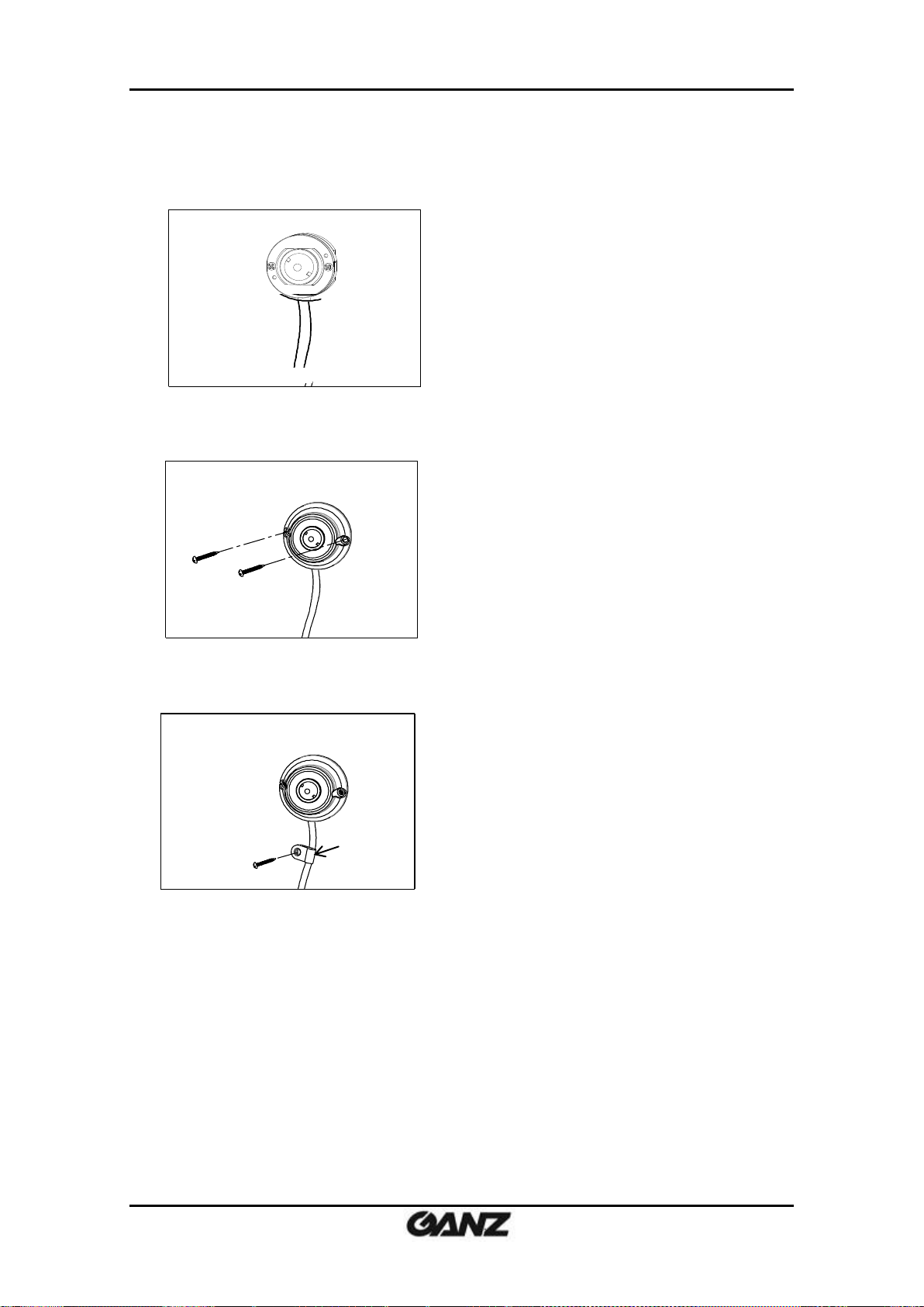
2) Cover the camera with the surface mount
bracket by routing the camera’s cable into
the cable holder on the bracket. Then, fasten
the bracket using the tapping screws (M3x20)
and anchor blocks appropriate for the
material of the installation surface.
3) Use the cable clamp optionally if you want to
fix the camera’s cable to a desired spot with a
tapping screw (M4x20).
cable clamp
1) Place the camera on a desired installation
surface.
Surface Installation for fixed angle
06-2014-B 11

PixelPro GXi Series ZN1-V4FN3/FN4 Installation Guide
3) Insert the rotate ring into the bracket by
pressing it into the bracket’s mount ring.
4) Place the camera unit on the pan/tilt bracket.
6) Use the cable clamp optionally if you want
to fix the camera’s cable to a desired spot
with a tapping screw (M4x20).
mount ring
rotate ring
cable clamp
1) Drill a hole on a desired installation surface,
and insert an anchor block into the hole.
2) Fix the pan/tilt bracket by inserting the
tapping screw (M4x25) to be passed
through the screw hole on the bracket and
tightening it into the anchor block.
5) Place the surface mount bracket on top of the
camera, fix the bracket by inserting the tapping
screws (M3x6) into the screw holes on the
bracket by aligning the screw holes with the
holes on the rotate ring on the pan/tilt bracket,
and tighten the screws.
Surface Installation for pan/tilt adjustment
06-2014-B 12

PixelPro GXi Series ZN1-V4FN3/FN4 Installation Guide
1) Pull out both slide plates at the bottom of the main
unit.
2) Place the main unit on the installation surface by
facing the bottom of the main unit toward the
installation surface, and mark the drilling spots
based on the alignment holes on the slide plates.
3) Drill the marked spots with a screw driver.
4) Insert the anchor blocks to the drilled holes, and
tighten them into the installation surface.
5) Place the main unit in the same way as in 2), and
insert the tapping screws to be passed through the
alignment holes on the main unit.
6) Tighten the screws into the anchor blocks to
fix the main unit to the installation surface.
4.2. Main Unit Installation
The main unit can be mounted on the installation surface by the built-in slide
plates.
06-2014-B 13

PixelPro GXi Series ZN1-V4FN3/FN4 Installation Guide
4.3. Setting the Image Attribute
Through the camera’s webpage, users can configure image settings. The menu of image
attribute is available under Video Appearance menu in Setup > Video & Audio > Camera. The
following features can be adjusted: Brightness, Contrast, Saturation, Sharpness and
orientation
For more detailed information, refer to the provided “PixelPro GXi series Web Page User's
Manual”.
06-2014-B 14

PixelPro GXi Series ZN1-V4FN3/FN4 Installation Guide
DO
Function
Specifications
C
Ground
1
Output
0 to 24 VDC
Max load: 50mA
DO
COM
Relay Type
Device
Internal
C 1 C
1
DO
DI
1)
2)
3)
4)
5. CONNECTIONS
DI/DO terminal connector
1) Connect external input/output devices (e.g. alarm device) optionally if they are necessary.
Refer to the reference below for the appropriate connections.
DO (Alarm) – For connecting an external device such as relays and LEDs.
Do the electrical wiring correctly referring to the following information.
Then, the connected device can be activated via its webpage.
Go to “6. CONFIGURATION” for more details for its setting.
06-2014-B 15

PixelPro GXi Series ZN1-V4FN3/FN4 Installation Guide
DI
Function
Specifications
C
Ground
1
Input
0 to 5 VDC
Max load: 50mA
+3.3V
DI
COM
DI
COM + -
Relay Type
Voltage Type
+
-
Output of
Sensor
Output of
Sensor
Internal
Internal
+
-
DI (Sensor) – For connecting a device such as a PIR and a door/window sensor.
Do the electrical wiring correctly referring to the following information.
Then, the connected device can be activated via its webpage.
Go to “6. CONFIGURATION” for more details for its setting.
Camera connector
2) Connect the camera unit to the main unit by inserting the camera’s DIN connector to the
camera’s connector on the main unit by placing the arrow mark on the camera’s DIN
connector upward like the image below.
06-2014-B 16

PixelPro GXi Series ZN1-V4FN3/FN4 Installation Guide
1) Open the ferrite core by lifting the clip.
2) Make one loop with the cable through the ferrite core. (See the enlarged image above.)
3) Close the ferrite core to hold the cable loop in the ferrite core’s chamber.
LAN connector
3) Connect the main unit to the network using an Ethernet cable (RJ45). Then, install the ferrite
core on the Ethernet cable. Refer to the explanations below for the ferrite core installation.
In case you intend to power the device using the LAN cable, a PoE switch should be available
in your network. Refer to “Appendix (B): Power over Ethernet” for more details.
Use of the ferrite core
Installation of the provided ferrite core is highly recommended to reduce high frequency
electrical noise level. Here below are the instructions to install the ferrite core on the Ethernet
cable.
Power connector
4) Connect a 12VDC power adaptor to the power connector on the main unit.
If the camera is powered via PoE, a power adaptor is not necessary to be connected to the
main unit.
06-2014-B 17

PixelPro GXi Series ZN1-V4FN3/FN4 Installation Guide
MAC address = 00-1C-B8-01-23-45 → IP address = 192.168.35.69
Convert the last two sets of hexadecimal numbers to decimal numbers.
6. CONFIGURATION
6.1. Set up network environment
The default IP address of the device is 192.168.XXX.XXX. Users can identify the IP address of the
device from converting the MAC address’s hexadecimal numbers, which is attached to the
device. Be sure that the device and PC are on a same area network before running the
installation.
IP address : 192.168.xxx.xxx
Subnet mask: 255.255.0.0
6.1.1. Generic IP Environment
In case of generic private network environment where IP address 192.168.XXX.XXX are used,
users may view the live streaming images on a web page using the device’s default IP address:
Convert the device’s MAC address to the IP address. Refer to the Hexadecimal-Decimal
Conversion Chart at the end of the manual.
(The MAC address of the device is attached on the side or bottom of the device.)
1. Start the Microsoft® Internet Explorer web browser and enter the address of the device.
2. Web streaming and device configurations are supported through ActiveX program. When the
ActiveX installation window appears, authorize and install the ActiveX.
06-2014-B 18

PixelPro GXi Series ZN1-V4FN3/FN4 Installation Guide
6.1.2. Custom IP Environment
IPAdminTool is a management tool, which automatically scans all of the network products for
users to perform administrative tasks, which includes network configurations, firmware update,
device reboot, and device organizations.
To modify the device’s default IP address for customized network area;
1. Find the device from the IPAdminTool’s list and highlight the device’s name.
2. Right-click the mouse and select “IP Address”; IP Setup window appears.
3. In the IP Setup’s window, information under “Local Network information” displays the
user/PC’s network area information. Those information need to be incorporated to the IP
Address, Subnet Mask, Gateway, and DNS boxes, except the last 2 sets of IP Address, which
are to be the unique numbers for the device. Refer to the image above for the setting
4. Click “Setup” to complete the modification.
06-2014-B 19

PixelPro GXi Series ZN1-V4FN3/FN4 Installation Guide
Note
i
Depending on system OS and Internet Explorer version, installation experience
may differ from one another. Figures described above are from Windows 7,
Internet Explorer 9 environment.
6.2. View video on web page
Type the proper IP address to view the live streaming images through a web browser.
The default username and password is root / pass.
6.2.1. ActiveX Installation
1. When the browser asks to install the AxUMF software, click “Install” to proceed.
2. When Setup installation pop-up window appears, click “Install” to proceed with rest of
installations.
06-2014-B 20

PixelPro GXi Series ZN1-V4FN3/FN4 Installation Guide
Caution
!
Whether directly accessing the streaming video through typing IP address on a
web page or taking steps through IPAdminTool, the ActiveX is needed to be
installed for the Microsoft® Internet Explorer to have the complete
configuration privileges.
6.2.2. View video using IPAdmin Tool
IPAdminTool automatically searches all activated network encoders and IP cameras and shows
the product name, IP address, MAC address and etc.
1. From the IPAdminTool’s product list, select the device by highlighting it.
2. Right-click the mouse and select “Web view”.
3. The system’s default web browser opens the device’s address.
06-2014-B 21

PixelPro GXi Series ZN1-V4FN3/FN4 Installation Guide
Caution
!
Please do not hold for more than 2 seconds. Otherwise, the camera may be
switched to its Factory Default settings.
Note
i
The factory default settings can be inferred as follows:
IP address: 192.168.xx.yy
Network mask: 255.255.0.0
Gateway: 192.168.0.1
User ID: root
Password: pass
6.3. Reset
Perform the following procedures to reset your device:
1. Press the reset button for 2 seconds while the device is in use.
2. Wait for the system to reboot.
.
6.4. Factory Default
Resetting the device back to the factory default will initialize all parameters including the IP
address back to the factory defaults. To reset back to the factory default:
1. Press the reset button and hold.
2. Release the button after 10 seconds.
3. Wait for the system to reboot.
06-2014-B 22

PixelPro GXi Series ZN1-V4FN3/FN4 Installation Guide
Note
i
There are two types of firmware files when you receive a firmware folder from
your vendor. When you need to update the firmware as the final resolution in case
your device is in safe mode like above, ensure that the firmware means the
firmware file for the device with the file name as GXi-V.1.X.X.X-~~~.enc.
Browse
6.5. Safe Mode
What is Safe Mode?
Your IP camera or encoder could encounter an unexpected occasion such as broken firmware
file or uncompleted loading of firmware file during system booting. To restore the device from
the occasions, the device provides the emergency firmware as a factory default. Your device
will get restarted with safe mode when there is any error on your booting system files.
Why does your IP camera or encoder boot in Safe Mode?
Normally, the cause of ‘safe mode’ is classified into two types.
* When the power supply is unplugged in the middle of system booting.
* When the firmware files required for system booting are damaged.
IMPORTANT: Your device will turn into the safe mode when it fails to boot certain times.
How to recover your system from Safe Mode
The messages above will appear on the webpage when your device has been rebooted in ‘safe
mode’. Then, you should follow the instructions on the webpage according to the steps in a
row.
06-2014-B 23

PixelPro GXi Series ZN1-V4FN3/FN4 Installation Guide
Note
i
There is another method to update firmware, which is using IPAdminTool.
Please refer to ‘IPAdminTool User’s Manual.pdf’ for the detailed procedure.
Note
i
If your device is still at safe mode after trying to update firmware, please contact
your local agency to get further assistance.
* Firmware update for safe mode itself: If you want to update the firmware for safe mode, you
should upload a firmware file with the following file name: GXi-SAFEMODE.~~~.enc.
06-2014-B 24

PixelPro GXi Series ZN1-V4FN3/FN4 Installation Guide
Camera Module
CMOS
Image Sensor
1/3” 1080p CMOS
Effective Pixels
1920 x 1080
Scanning system
Progressive scanning
ELECTRICAL
Resolution
1920 x 1080
Min.
Illumination
ZN1-V4FN4
Color: 1.4Lux / BW: 0.01Lux (DSS ON)
ZN1-V4FN3
Color: 1.0Lux / BW: 0.007Lux (DSS ON)
AGC Control
Auto
Lens
ZN1-V4FN4
3.7mm, F2.5, Angle of View: approx. 63°(H), 33°(V)
ZN1-V4FN3
2.8 mm, F2.0, Angle of View: approx. 82°(H), 43°(V)
Day & Night
Digital Day & Night
Wide Dynamic Range
Digital WDR
Video
Compression Format
H.264 Baseline, Main, High profile(MPEG-4 Part 10/ AVC),
MJPEG(Motion JPEG)
Number of Streams
Dual Stream, Configurable streams in H.264, MJPEG
H.264: Controllable frame rate, bandwidth(VBR/CBR)
MJPEG: Controllable frame rate, JPEG quality
Resolution
1920x1080, 1280x720, 1120x630, 960x540, 800x450,
640x360, 480x270, 320x180
Compression FPS
30fps@1080p
Motion Detection
Built-in
Burnt-in Text (Digital)
Video stream overlay text
Audio
Input/output
-
Compression Format
-
Function
Digital Input/output
1/1 channel
RS-485
-
Network
10/100 Base-T
Power over Ethernet (PoE)
Supported
Protocol
QoS Layer 3 DiffServ, TCP/IP, UDP/IP, HTTP, HTTPS, RTSP,
RTCP, RTP/UDP, RTP/TCP, mDNS, UPnP™, SMTP, DHCP, DNS,
DynDNS, NTP, SNMPv1/v2c/v3(MIB-II), IGMP, ICMP,
SSLv2/v3, TLSv1
SD Slot
1 microSD slot(up to 64GB)
※ Micro SD Card is not included
(Recommend Class 4 and higher for HD recordings)
APPENDIX (A): SPECIFICATIONS
Summary
06-2014-B 25

PixelPro GXi Series ZN1-V4FN3/FN4 Installation Guide
Power Source
12VDC / PoE (IEEE802.3af )
Power Consumption
3.6W @ 12VDC
Video Output
-
Audio Input
-
Audio Output
-
D/I
Max 50mA@5VDC, TTL level 1.5V threshold
D/O
Max 50mA@24VDC
On-state resistance:50 Ω (max continuous)
Operating Temperature
Operating Range
-10 ˚C ~ +50 ˚C (14˚F ~ 122˚F)
(Not Include Cold Start)
Operating Humidity
Up to 85% RH
Material
Polycarbonate
Color
White
Dimension
Main Unit: 107 x 124 x 36 mm
Camera Unit : 28.1(Ø) x 25 mm
Covert Cover: 34(Ø) x 26 mm
Surface Mount Bracket: 44(Ø) x 23mm
Pan/Tilt Bracket: 44(Ø) x 34mm
Cable Length: 6.1m(20ft)
Weight (Approx.)
Main Unit: 225g
Camera Unit: 250g
Electrical Characteristics
Environment Condition
Mechanical Condition
* The specifications and/or appearance of the product may change without a prior notice.
06-2014-B 26

PixelPro GXi Series ZN1-V4FN3/FN4 Installation Guide
Property
802.3af
802.3at
Available Power
12.95 W
25.50 W
Max. Power by PSE
15.40 W
34.20 W
Max. Current
350 mA
600 mA
Supported Cable
Category 3 or higher
Category 5 or higher
Note
i
For proper activation of PoE, the Category 5 cable must be shorter than 100m and
conform the PoE standard.
Note
i
With non-Power Sourcing Equipment (non-PSE)
When it is connected with non PSE, the power adaptor should be connected.
With power adaptor
Connecting both PSE and power adaptor does not do any harm to the product.
Disconnecting PSE or power adaptor from device does not reboot the device as
long as either one is connected to the device.
APPENDIX (B): POWER OVER ETHERNET
The Power over Ethernet (PoE) is designed to extract power from a conventional twisted pair
Category 5 Ethernet cable, conforming to the IEEE 802.3af Power-over-Ethernet (PoE) standard.
The IEEE 802.3af allows for two power options for Category 5 cables.
The IEEE 802.3af-2003 standard allows up to 15.4 W of power to device. However, 12.95W is
the available power, as some power gets lost in the cable.
The updated IEEE 802.3at-2009 (PoE+) standard allows up to 25.5W (Max 34.2 W) of power to
device. PoE has advantages over conventional power in such places where AC powers cannot
be reached or is expensive to wire.
Power Comparison
The PoE Property supported by the device is 802.3af.
06-2014-B 27

PixelPro GXi Series ZN1-V4FN3/FN4 Installation Guide
APPENDIX (C): DIMENSIONS
[ Main Unit ]
(Unit: mm)
06-2014-B 28

PixelPro GXi Series ZN1-V4FN3/FN4 Installation Guide
[ Camera Unit ]
(Unit: mm)
06-2014-B 29

PixelPro GXi Series ZN1-V4FN3/FN4 Installation Guide
mm
mm
Covert Cover
mm
mm
mm
Surface Mount Bracket
Pan / Tilt Bracket
[ Bracket ]
06-2014-B 30
(Unit: mm)

PixelPro GXi Series ZN1-V4FN3/FN4 Installation Guide
Hex
Dec
Hex
Dec
Hex
Dec
Hex
Dec
Hex
Dec
Hex
Dec
Hex
Dec
0 0 25
37
4A
74
6F
111
94
148
B9
185
DE
222 1 1
26
38
4B
75
70
112
95
149
BA
186
DF
223
2 2 27
39
4C
76
71
113
96
150
BB
187
E0
224 3 3
28
40
4D
77
72
114
97
151
BC
188
E1
225
4 4 29
41
4E
78
73
115
98
152
BD
189
E2
226
5 5 2A
42
4F
79
74
116
99
153
BE
190
E3
227 6 6
2B
43
50
80
75
117
9A
154
BF
191
E4
228 7 7
2C
44
51
81
76
118
9B
155
C0
192
E5
229 8 8
2D
45
52
82
77
119
9C
156
C1
193
E6
230 9 9
2E
46
53
83
78
120
9D
157
C2
194
E7
231
0A
10
2F
47
54
84
79
121
9E
158
C3
195
E8
232
0B
11
30
48
55
85
7A
122
9F
159
C4
196
E9
233
0C
12
31
49
56
86
7B
123
A0
160
C5
197
EA
234
0D
13
32
50
57
87
7C
124
A1
161
C6
198
EB
235
0E
14
33
51
58
88
7D
125
A2
162
C7
199
EC
236
0F
15
34
52
59
89
7E
126
A3
163
C8
200
ED
237
10
16
35
53
5A
90
7F
127
A4
164
C9
201
EE
238
11
17
36
54
5B
91
80
128
A5
165
CA
202
EF
239
12
18
37
55
5C
92
81
129
A6
166
CB
203
F0
240
13
19
38
56
5D
93
82
130
A7
167
CC
204
F1
241
14
20
39
57
5E
94
83
131
A8
168
CD
205
F2
242
15
21
3A
58
5F
95
84
132
A9
169
CE
206
F3
243
16
22
3B
59
60
96
85
133
AA
170
CF
207
F4
244
17
23
3C
60
61
97
86
134
AB
171
D0
208
F5
245
18
24
3D
61
62
98
87
135
AC
172
D1
209
F6
246
19
25
3E
62
63
99
88
136
AD
173
D2
210
F7
247
1A
26
3F
63
64
100
89
137
AE
174
D3
211
F8
248
1B
27
40
64
65
101
8A
138
AF
175
D4
212
F9
249
1C
28
41
65
66
102
8B
139
B0
176
D5
213
FA
250
1D
29
42
66
67
103
8C
140
B1
177
D6
214
FB
251
1E
30
43
67
68
104
8D
141
B2
178
D7
215
FC
252
1F
31
44
68
69
105
8E
142
B3
179
D8
216
FD
253
20
32
45
69
6A
106
8F
143
B4
180
D9
217
FE
254
21
33
46
70
6B
107
90
144
B5
181
DA
218
FF
255
22
34
47
71
6C
108
91
145
B6
182
DB
219
23
35
48
72
6D
109
92
146
B7
183
DC
220
24
36
49
73
6E
110
93
147
B8
184
DD
221
APPENDIX (D): HEXADECIMAL-DECIMAL
CONVERSION TABLE
Refer to the following table when converting the MAC address of the device to the IP address.
06-2014-B 31

PixelPro GXi Series ZN1-V4FN3/FN4 Installation Guide
06-2014-B 32

PixelPro GXi Series ZN1-V4FN3/FN4 Installation Guide
06-2014-B 33

PixelPro GXi Series ZN1-V4FN3/FN4 Installation Guide
06-2014-B 34

PixelPro GXi Series ZN1-V4FN3/FN4 Installation Guide
MAN#
DATE(M/D/Y)
Comments
06-2014-A
06/06/2014
First release version
06-2014-B
06/10/2014
Revised screws information
REVISION HISTORY
06-2014-B 35
 Loading...