

Page 1
Page 1
CBC Americas Corp.
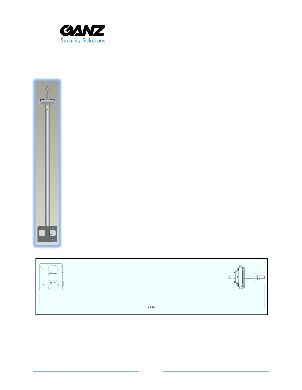
Overall dimension in inches for ZMA-PM6
55 Mall Drive
www.ganzsecurity.com
Tele: 631-864-9700
Commack, NY 11725
Adjustable Length LCD Monitor Mount Information
These LCD monitor mounts are designed for easy installation and adjustability.
The mount will support a large range of monitors up to a maximum weight of 55
lbs. The mounting bracket has an integral VESA pattern for 75mm or 100mm
standard bolt-hole locations. Optional adapter plates are available to
accommodate monitors with mounting patterns that vary from this standard.
The mount can be used with an existing building’s truss structure or in
conjunction with a supporting channel strut installation. It can, also, mount
directly to flat ceiling surfaces by removing the threaded rod channel truss plate.
Standard units are available in black. Additional colors are available by special
order. Please contact your Sales Representative or the manufacturer for details in
matching the correct monitor and mounting solution to the specific application
requirements for best system performance.
These two standard models are available:
ZMA-PM6 LCD Monitor Mount, Adjustable from 36-inches to 67-inches
ZMA-PM12 LCD Monitor Mount, Adjustable from 70-inches to 138-inches
Both models are identical in construction, they only vary in length.
©2014 CBC Americas Corp.
Page 2

Page 2
IMPORTANT SAFEGUARDS
1. Read Instructions - All the safety and installation instructions should be read before the unit is used.
2. Retain Instructions - The safety and operating instructions should be retained for future reference.
3. Heed Warnings - All warnings on the unit and in the instructions should be adhered to for safe use.
4. Follow Instructions - All installation and use instructions should be followed.
5. Cleaning - Use a damp cloth for cleaning.
6. Do not use attachments not recommended by the product manufacturer as they may cause hazards.
7. Power-Cord Protection - Power-supply cords should be routed so that they will not be pinched or cut, paying
particular attention to cords and plugs, convenience receptacles, and the point where they exit from the appliance.
8. Power Lines - An outdoor system should not be located in the vicinity of overhead power lines or other electric
light or power circuits, or where it can fall into such power lines or circuits. When installing an outdoor system,
extreme care should be taken to keep from touching such power lines or circuits as contact with them might be
fatal. U.S.A. models only - refer to the National Electrical Code Article 820 regarding installation of CATV systems.
9. Overloading - Do not overload outlets and extension cords as this can result in a risk of fire or electric shock.
10. Replacement Parts -When replacement parts are required, be sure the service technician has used replacement
parts specified by the manufacturer or have the same characteristics as the original part. Unauthorized
substitutions may result in product failure or other hazards.
1. UNPACKING
Check for the following items:
• Verify the unit model number.
• Verify that parts listed below have been included.
If an item appears to have been damaged in shipment, replace it properly in its carton and notify the shipper. If
any items are missing, notify your dealer, Sales Representative or Customer Service.
1 x Adjustable Length LCD Monitor Mount with VESA Mounting Bracket
Hardware Kit
1 x Safety Cable
1 x U-bolt Cable Clamp
4 x 4mm x 8mm screws
4 x 4mm washers
2. INSTALLATION
Tools required:
PH2 Phillips Screw Drive
7/16” Wrench (2)
11/32” Wrench
3/8” Wrench
Level
Optional: Adjustable Wrench
For Channel or Truss Installation
3/4” Wrench
For Flat Ceiling Installation
Mounting Hardware is not included. The appropriate fasteners must be used based on the weight to be supported
and the backing material or anchors used to support the mount and monitor from the ceiling. Choose appropriate
tools to complete this installation for the anchoring and fastening system to be used for proper installation.
Caution: Maximum Monitor weight cannot exceed 55 pounds (25kg).
©2014 CBC Americas Corp.
Page 3

Page 3
For Channel or Truss Installation
½”-13 Locking Nut
½” Fender Washer
Building Structure
¼”-20 Leveling Locking Nuts
Rotational Locking Screws
¼”-20 Height Adjustment Bolt and Thumb Nut
#8-32 Angle Adjustment Screw
¼”-20 VESA Plate Bolt Mounting Bolt
VESA Plate
Hole for Safety Cable Installation
1. Choose desired location for monitor mount installation. Verify mounting structure and
surfaces are capable of supporting the monitor and no obstacle or interference is present
from existing installed devices or wiring.
2. Insert threaded rod into gap between lower truss angles or into hole of channel strut.
3. Place large fender washer over threaded rod.
4. Tighten ½-13 locking nut using 3/4” wrench until firmly fixed.
5. Tighten ¼-20 locking nuts (4x) using 7/16” wrench until a minimum of four threads extend
through the nut. After monitor is mounted use these nuts to plumb the horizontal level of
the monitor by tighten each nut until desired position is achieved.
6. Adjust the height of monitor mounting bracket by removing the ¼-20 thumb nut and bolt.
Note: Based on the position of the VESA pattern on the monitor the approximate position of
the monitor can be set by measuring from the center of mounting pattern to bottom of
monitor. Measure from the floor to the mounting point of bracket to set the distance the
bottom edge of the monitor will be above the floor.
Once position is determined insert ¼-20 bolt at vertical hole location nearest to this position
and tighten thumb nut.
©2014 CBC Americas Corp.
Page 4

Page 4
Mounting Monitor to Bracket
7. Remove VESA plate from mount.
8. Attach plate to monitor.
Note: Verify the size and length of screw required for the monitor to be mounted per
manufacturer’s instructions. There are four 4mmx 8mm screws and washers provided. Only
use these screws if appropriate for the installation ensuring the monitor will be securely
attached and screw length is not too long to damage monitor.
9. Attach monitor to vertical pole on the mount. Using 7/16” wrench, securely tighten the
¼-20 mounting bolt
10. Adjust angle of the monitor and securely tighten #8-32 locking nut with 11/32” wrench.
11. Rotate monitor and pole to position viewing direction of monitor.
12. Lock viewing direction by equally tightening the four Phillips head screws located directly
below the strut mounting bracket.
13. Level the monitor by tightening the four ¼-20 nuts on the strut mounting bracket (refer to
step 5).
Install safety cable
14. Thread safety cable through hole in lower edge of monitor mounting bracket and up
through mounting pole.
15. Pull cable out of oval cut-out in pole at the top end of the mount and loop it around a
secure building support or part of the building structure.
16. Pull the slack out of the cable and secure the loop end with the cable clamp. Tighten U-bolt
clamp with 3/8” wrench. Secure or cut excess cable.
©2014 CBC Americas Corp.
 Loading...