

Ganz ZC-YHW702 Series Operation Manual

Operation Manual
CCD CAMERA
ZC-YHW702 Series
En-1
Read the “Instructions for Use” prior to operation.
Retain this operation manual for future reference.
Follow these important safety instructions at all times.
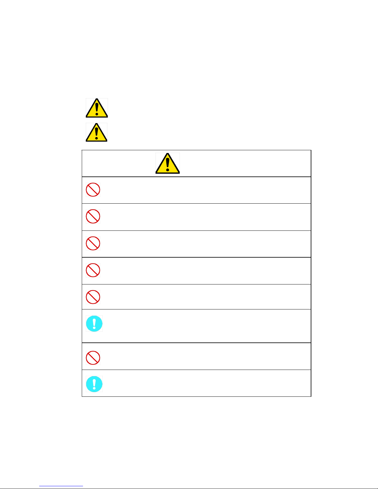
Heed the following explanations of “Warning” and “Caution”.
Indicates danger of death or injury to the user if not
operated properly.
Indicates danger of injury to the user or material
damage if not operated properly.
㻃 Warning
Do not open the cover or disassemble the main casing.
This may result in burns or injury due to contacting high temperature areas
inside the main body or damaged part.
Do not insert foreign objects.
Do not spill liquids or drop flammable items or metal inside.
This may cause fire. Disconnect the power plug and contact a dealer.
Do not use in conditions such as rain, water, moisture, dust,
greasy fumes and hot air.
This may cause fire.
Do not place in the vicinity of thermal appliances.
This may cause the casing to warp or high temperatures inside the device
which could result in fire.
Avoid direct sunlight.
This may cause high temperatures inside the device which could result in fire.
Disconnect the cables immediately upon detecting smoke or an
unusual odor.
Subsequent to disconnecting power, confirm that there is no smoke or unusual
odor and contact a dealer. Failing to do so may result in fire.
Do not touch the device or the connecting cables in the case of
lightning.
This may cause electric shock.
Ask a dealer for installation.
Failing to do so may result in fire, electric shock and accident.
Cautio
En-2
㻃 Caution
Turn off the power before connecting any devices.
Failing to do so could result in electric shock or fire.
Make sure that connecting cables are inserted fully.
Failing to do so can result in fire.
Disconnect the power and cables before moving the device.
Failing to do so can result in injury and damage to the device.
Install connecting cables in an area where they won’t be
pulled or be caught.
Failing to do so can result in injury.

Item Page
Introduction 4
Instructions for Use 4
Component Names and Functions 5
Lens Mounting 6
Wiring Connector 6
Applicable Lenses 6
Lens Adjustment 6
Back Focus Adjustment 7
Connecting the Power 8
Connecting the AC Power 8
Connecting the DC Power 8
Settings for Various Functions 9
Settings Operation 11
Setting Items 11
Mode Select (MODE SELECT) 11
Settings for the Exposure Function (CONFIGURATION) 13
Settings for Other Functions (FUNCTION SE T.) 15
Camera Setup (CAMERA SETUP) 19
Lens Setup (LENS SETUP) 19
Mode Save (MODE SAVE) 20
Defect Correction (WHITE SPOT CORRECTION) 20
Initialize (INITIALIZE) 21
External Control Signal Terminal 22
Connection 22
Settings 23
Specifications 24
En-3
Table of Contents

Thank you for purchasing our product.
This device is a multifunctional, high performance CCD camera developed for high end
security.
The characteristics of this camera are as follows.
(1) Wide dynamic range function (WD)
Displays both light and dark objects at the same time (Dynamic range of 60-dB max).
(2) Day and Night modes (DAY & NIGHT)
Displays a high quality color picture during the day and a clear black and white picture at
night.
(3) Electronic sensitivity UP function (SENS UP)
(4) Electronic zoom function (E-ZOOM)
(5) On screen display function (OSD)
(6) High definition
Area to use/store
This device is an indoor camera. Do not use it outside.
Do not expose the camera to extreme light sources (lighting and sunlight) regardless of use.
Avoid using and storing in the following locations.
Extremely hot or cold locations (operating temperature -10C to +50C)
High humidity or dusty locations
In rainy locations or locations exposed to water
Locations exposed to rigorous vibration
Near TV and radio transmitting station with strong signals
Care
Wipe dirt off the casing with a soft dry cloth. For heavy soil, wipe off using a dry cloth after
cleaning with a cloth with a small amount of mild detergent. Disconnect the power cord prior
to cleaning.
Do not use flammable liquids such as alcohol, benzene or thinner. This may damage the
surface finish.
Do not touch the surface of the CCD. If it gets dusty, wipe off with lens cleaning paper.
Other
White spots may appear on the screen due to normal characteristics of the imaging device.
However, this is not a defect.
White spots may also be noticeable when using the electronic sensing UP function (SENS
UP). However, this is not abnormal.
Colors may differ somewhat from actual colors depending on the lighting but this is not a
defect.
Highly light-intensive objects (such as lamps) may cause vertical stripes to appear on the
screen. This is a normal characteristic of the imaging device and is not a defect.
En-4
Instructions for Use
Introduction
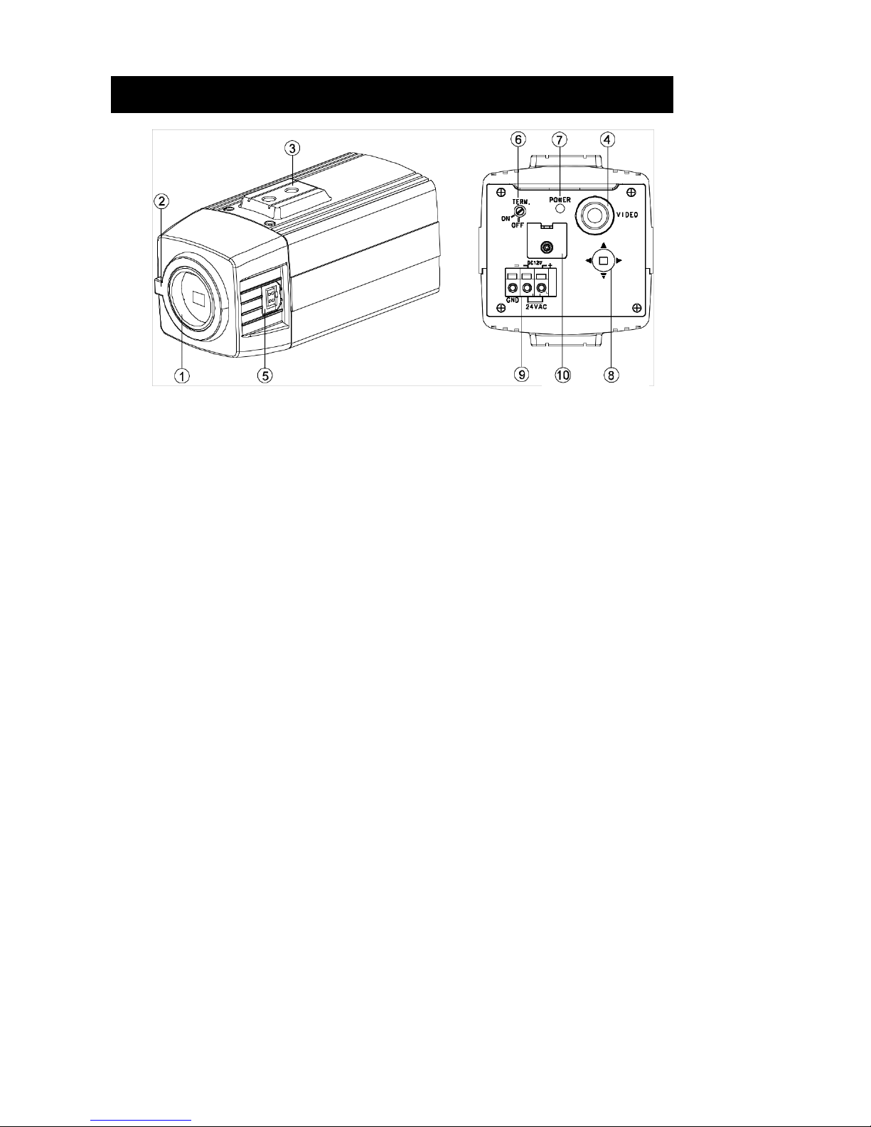
ձ Lens mount
A suitable type CS mount lens may be attached. C mount lenses can be attached using a
C/CS mount adapter.
ղ Back focus lock screw
A ALLEN WRENCH can be inserted here to stabilize the lens mount using a screw to
adjust the distance between the lens mounting surface and the imaging surface. Refer to
“Lens Mounting: Back Focus Adjustment” for adjustment.
ճ Camera mount area
The camera can be mounted using either the top or bottom of the main body. Use 1/4 - 20
screw for mounting.
մ VIDEO OUT (Video output) terminal
This is an output terminal for the video signal. (BNC type)
յ Lens terminal
4 Pin connector for an auto iris lens. Refer to “Lens Mounting: Wiring Connector” for wiring.
ն RS485 Terminal switch
Use this when connecting an external device using the external control terminal of this
device.
ON: Terminal with 100 Ω. OFF: No terminal
շ Power indicator light
This lights up when powered on.
ո Switch for function settings
This is a switch for the function settings. This is used when a menu is displayed and
settings are determined.
For details, refer to “Settings for Various Functions: Settings Operation”.
չ Power input terminal
This is the input terminal where power is supplied. This uses both 12 V DC and 24 V AC.
պ External control terminal
This can be used to connect an RS-485 I/O compatible terminal. It can also be used for an
external control terminal for the DAY & NIGHT function. For details, refer to "External
Control Signal Terminal".
Component Names and Functions
En-5
Figure 1
Top Front View
Rear View
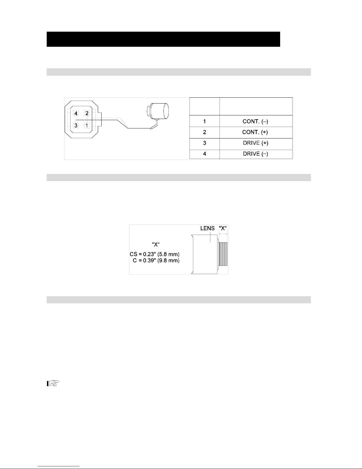
This device uses a DC voltage auto iris lens. A VIDEO signal control lens can not be used.
Wiring Connector 㻃 㻃 㻃 㻃 㻃 㻃 㻃 㻃 㻃 㻃 㻃 㻃 㻃 㻃 㻃 㻃 㻃 㻃 㻃 㻃 㻃 㻃 㻃 㻃 㻃 㻃 㻃 㻃 㻃 㻃 㻃 㻃 㻃 㻃 㻃 㻃 㻃 㻃 㻃 㻃 㻃 㻃 㻃 㻃 㻃 㻃 㻃 㻃 㻃
Refer to chart 1 for the connector wiring diagram.
Applicable Lenses 㻃 㻃 㻃 㻃 㻃 㻃 㻃 㻃 㻃 㻃 㻃 㻃 㻃 㻃 㻃 㻃 㻃 㻃 㻃 㻃 㻃 㻃 㻃 㻃 㻃 㻃 㻃 㻃 㻃 㻃 㻃 㻃 㻃 㻃 㻃 㻃 㻃 㻃 㻃 㻃 㻃 㻃 㻃 㻃 㻃 㻃 㻃 㻃 㻃
Lenses can be used, which have a thread length less than that specified below. Longer lenses
may damage the imaging device.
Back focus is adjusted for CS mount type lenses when this device is shipped.
Use a C/CS mounting adaptor to attach a C mount lens.
Lens Adjustment 㻃 㻃 㻃 㻃 㻃 㻃 㻃 㻃 㻃 㻃 㻃 㻃 㻃 㻃 㻃 㻃 㻃 㻃 㻃 㻃 㻃 㻃 㻃 㻃 㻃 㻃 㻃 㻃 㻃 㻃 㻃 㻃 㻃 㻃 㻃 㻃 㻃 㻃 㻃 㻃 㻃 㻃 㻃 㻃 㻃 㻃 㻃 㻃 㻃 㻃
Adjust the mechanical iris lens.
Mount the lens on this device and adjust the lens before using.
Operating procedure
1. Move the cursor to “LENS SETUP” and press the switch. The “LENS SETUP” screen is
displayed.
2. Move the cursor to “INITIAL FINE ADJ.” and press the switch.
Move the cursor to “OK” and press the switch. Adjustment will be carried out.
Carry out adjustment using a bright light source with no flicker.
3. The “LENS SETUP” screen will be displayed upon completion of adjustment.
Note) Repeat this adjustment procedure any time a lens is replaced.
Lens Mounting
En-6
(Appearance of the connector entry point)
Auto iris lens
Connector
Connector
Pin No.
DC voltage drive
Auto iris lens
Chart 1
Figure 2
Figure 3
Back Focus Adjustment 㻃 㻃 㻃 㻃 㻃 㻃 㻃 㻃 㻃 㻃 㻃 㻃 㻃 㻃 㻃 㻃 㻃 㻃 㻃 㻃 㻃 㻃 㻃 㻃 㻃 㻃 㻃 㻃 㻃 㻃 㻃 㻃 㻃 㻃 㻃 㻃 㻃 㻃 㻃 㻃 㻃 㻃 㻃 㻃 㻃
The factory settings include back focus adjustment for a CS mount lens. However, adjustment
may be required depending on the lens used. Use the back focus adjustment function to do this.
Adhere to the following adjustment procedure.
Operating procedure
1. Push the function settings switch up. (Jump function). The back focus adjustment screen is
displayed. (Figure 4-1)
When this screen is displayed, the lens is open.
The back focus adjustment screen can also be reached from the “TOP MENU LENS SETUP”
screen using the “Setting Operation” procedure.
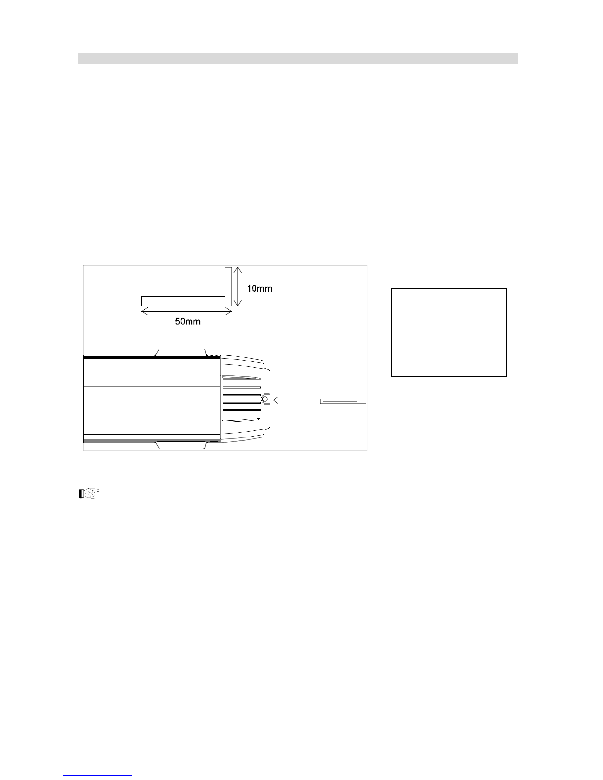
2. Loosen the back focus lock screw using the ALLEN WRENCH. Adjust the lens mounting to
fix the focus. Secure the lens mount with back focus lock screw.
3. Press the function settings switch to end the back focus adjustment.
Note)
Use the included ALLEN WRENCH for adjustment. Insert the long end of ALLEN WRENCH into
the adjustment hole of the camera.
Rotate it in a clockwise approximately 15 degrees to fasten the lens mount.
If the back focus lock screw is too tight, the threads of the lens mount may be damaged.
When using a zoom lens:
1. Objects further than 25 meters (70 feet) can be captured.
2. Set the focus to FAR.
3. Set the zoom to wide angle.
4. Complete the above procedures 1-3.
5. Set the zoom to telephoto.
6. Adjust the focus.
En-7
Figure 4
ALLEN WRENCH
Camera
EASY BACK FOCUS ADJ.
Figure 4-1
 Loading...