

Ganz ZC-PT Series Indoor User Manual

User’s Manual
1
Preface
The information given in this manual was current when published. The company reserves
the right to revise and improve its products. All specifications are subject to change without
notice.
Notice
To work with the Mini PTZ Cameras, any installer or technician must have the
following minimum qualifications:
• A basic knowledge of CCTV systems and components
• A basic knowledge of electrical wiring and low-voltage electrical
hookups
• A basic knowledge of network system setting
• Have read this manual completely
Copyright
Under copyright laws, the contents of this user manual may not be copied,
photocopied, translated, reproduced or reduced to any electronic medium or
machine-readable format, in whole or in part, without prior written permission
of the company.
Important Information
Before proceeding, please read and observe all instructions and warnings in
this manual. Retain this manual with the original bill of sale for future
reference and, if necessary, warranty service. When unpacking your unit,
check for missing or damaged items. If any item is missing, or if damage is
evident, DO NOT INSTALL OR OPERATE THIS PRODUCT. Contact your
dealer for assistance.
Regulation
This device complies with Part 15 of the FCC Rules.
Operation is subject to the following two conditions:
(1) this device may not cause harmful interference, and (2)
this device must accept any interference received, including
interference that may cause undesired operation.
User’s Manual
2
This symbol on the product or on its packaging indicates
that this product shall not be treated as household waste in
accordance with Directive 2002/96/EC. Instead it shall be
handed over to the applicable collection point for the
recycling of electrical and electronic equipment. By proper
waste handling of this product you ensure that it has no
negative consequences for the environment and human
health, which could otherwise be caused if this product is
thrown into the garbage bin. The recycling of materials will
help to conserve natural resources.
For more details information about recycling of this product,
please contact your local city office, your household waste
disposal service or the shop where you purchased the
product.
Compliance is evidenced by written declaration from our
suppliers, assuring that any potential trace contamination
levels of restricted substances are below the maximum
level set by EU Directive 2002/95/EC, or are exempted due
to their application.

User’s Manual
3
Cautions
• Handle the camera carefully
Do not abuse the camera. Avoid striking, shaking, etc. The camera could
be damaged by improper handing or storage.
• Installing electricity wiring carefully
Ask qualified personnel of electrical wiring for the installation. Please note
that input electricity to the unit is at tolerance of DC 12V/AC 24V ± 10%.
The camera is capable of surge protection; ensure AC power model unit
grounded appropriately against damage of heavy current or electric
shock.
• Do not disassemble the camera
To prevent electric shock, do not remove screws or covers. There are no
user serviceable parts inside. Ask a qualified service person for servicing.
• Do not block cooling holes on the bracket
This camera has a cooling fan inside. Blocking the cooling holes leads to
build up heat of the camera and may cause malfunction.
• Do not operate the camera beyond the specified temperature,
humidity or power source ratings
Use the indoor PTZ Camera under conditions where temperature is
between 0°C ~ 40°C (32°F ~ 104°F) and the outdoor camera under
conditions where temperature is between -30°C~45°C (-22°F~113°F), and
humidity is below 90%.
• Do not expose the indoor PTZ Camera to rain or moisture, or try to
operate it in wet areas
The indoor PTZ Camera is designed for indoor use or locations where it is
protected from rain and moisture. Turn the power off immediately if the
camera is wet and ask a qualified service person for servicing. Moisture
can damage the camera and also create the danger of electric shock.
• Do not use strong or abrasive detergents when cleaning the camera
body
Use a dry cloth to clean the camera when it is dirty. In case the dirt is hard
to be removed, use a mild detergent and wipe gently.

User’s Manual
4
• Never face the camera towards the sun
Do not aim the camera at bright objects. Whether the camera is in use or
not, never aim it at the sun or other extremely bright objects. Otherwise,
the camera may be smeared or damaged.

User’s Manual
5
Table of Contents
1. Overview.................................................................................................................................... 7
1.1 Product Features.............................................................................................................. 8
1.2 Product Application........................................................................................................... 9
2. Connecting the Mini PTZ Camera..........................................................................................10
2.1 Package Content............................................................................................................ 10
2.2 Switch/Connector Definition ............................................................................................11
2.3 Communication Switch Setting....................................................................................... 12
2.4 ID Setup.......................................................................................................................... 13
2.5 Camera Control Protocol Setup...................................................................................... 14
2.6 22-Pin Connector Definition............................................................................................ 15
2.7 RS-485 Connector Definition.......................................................................................... 16
3. Operation and Configuration.................................................................................................17
3.1 OSD Display Format....................................................................................................... 17
3.2 OSD Menu Tree.............................................................................................................. 18
3.3 Configuration Menu ........................................................................................................ 22
3.3.1 LANGUAGE ...................................................................................................... 22
3.3.2 DEFAULT CAMERA.......................................................................................... 23
3.3.3 BACKLIGHT...................................................................................................... 23
3.3.4 FOCUS ............................................................................................................. 23
3.3.5 AE MODE ......................................................................................................... 24
3.3.6 WBC MODE ...................................................................................................... 25
3.3.7 SETUP MENU 1................................................................................................ 26
・ DIGITAL ZOOM................................................................................................. 26
・ SLOW SHUTTER ............................................................................................. 26
・ DIGITAL NOISE REDUCTION (D.N.R.)............................................................ 27
・ IMAGE INVERSE.............................................................................................. 27
・ FREEZE............................................................................................................ 27
・ APERTURE....................................................................................................... 27
・ EXIT.................................................................................................................. 28
3.3.8 SETUP MENU 2................................................................................................ 28
・ FLIP .................................................................................................................. 28
・ ANGLE ADJUSTER .......................................................................................... 29
・ SPEED BY ZOOM ............................................................................................ 29
・ AUTO CALI. (Auto Calibration) ......................................................................... 29
・ PASSWORD ..................................................................................................... 29
・ OSD AUTO CLOSE .......................................................................................... 30
・ SYSTEM RESET .............................................................................................. 30
・ EXIT.................................................................................................................. 31
3.3.9 ID DISPLAY....................................................................................................... 31
3.3.10 TITLE DISPLAY ................................................................................................ 31
3.3.11 TITLE SETTING................................................................................................ 32

User’s Manual
6
3.3.12 PRESET............................................................................................................ 33
3.3.13 SEQUENCE...................................................................................................... 34
3.3.14 AUTOPAN ......................................................................................................... 35
3.3.15 CRUISE ............................................................................................................ 37
3.3.16 HOME SETTING............................................................................................... 39
3.3.17 IR FUNCTION................................................................................................... 41
3.3.18 ALARM SETTING............................................................................................. 42
3.3.19 ALARM DETECT .............................................................................................. 45
3.3.20 WDR FUNCTION.............................................................................................. 47
3.3.21 PRIVACY MASK ............................................................................................... 48
3.3.22 TIME SETTING................................................................................................. 50
3.3.23 SCHEDULE FUNCTION................................................................................... 51
3.3.24 EXIT OSD ......................................................................................................... 52
Appendix A: Technical Specification .......................................................................................... 53
Appendix B: Switch Settings Index Table................................................................................... 55
Camera ID Setup ...................................................................................................................... 55
Protocol Setup .......................................................................................................................... 62
Appendix C: OSD Menu Notes..................................................................................................... 63

User’s Manual
7
1. Overview
The Mini PTZ Camera is an innovative PTZ Camera designed for middle and
small surveillance applications and possesses true PTZ Camera features,
such as high speed and accurate Pan/Tilt, up to 12×12 zoom ratio, 180°
Digital Image Flip, Speed by Zoom, and Preset Speed up to 400°/s.
Additionally, it contains 256 Preset Points, 8 Sequence Lines, 4 Auto Pan
Lines and 8 Cruise Lines to support automatic operations. It is ideal for all
surveillance requirements in hotels, department stores, intelligent buildings,
amusement parks, parking lots, factories, hospitals, schools, stations etc.
The Mini PTZ Camera contains various solutions for low light and high
contrast conditions. For example, a bright background or shade can result in
the subject of the image appearing darker. The backlight compensation
function gives a bright and beautiful image.
The Mini PTZ Camera supports one cabling for easy installation, and can be
integrated with various digital surveillance products, such as DVRs, Control
Keyboards and various sorts of accessories for a total surveillance solution.
The camera is incorporated with multiple protocols: DynaColor, Pelco, VCL,
Philips, etc. to enhance powerful connectivity.

User’s Manual
8
1.1 Product Features
Precise and Accurate Mini PTZ Camera Performance
• High Resolution 540 TV lines
• Preset Speed up to 400°/sec
• Preset Accuracy of 0.225°
• 360° Endless Pan
• Proportional Pan & Tilt Speed
• Preset Positions / Auto-Pan / Sequence / Cruise
• Auto-Calibration
• Digital / Mechanical Image Flip (180°)
Dynamic PTZ Camera Applications
• Schedule function
• Multiple built-in protocols
• Extraordinary lightweight design for easy installation
• Vandal proof dome cover (Optional)
• Flexible indoor mountings
• 16 Privacy Masks
• Motion Detection
Superior Camera Image Quality
• 12× Optical Zoom
• 12× Digital Zoom
• Digital Slow Shutter
• Backlight Compensation
• Auto Focus
• Auto White Balance
• Auto Gain Control
• Auto Iris Control
• Auto-Calibration
• Removable IR Cut Filter
• Minimum Illumination: 0.1 Lux, 0.01 Lux (B/W)
• Wide Dynamic Range
• 2D / 3D Noise Reduction
User’s Manual
9
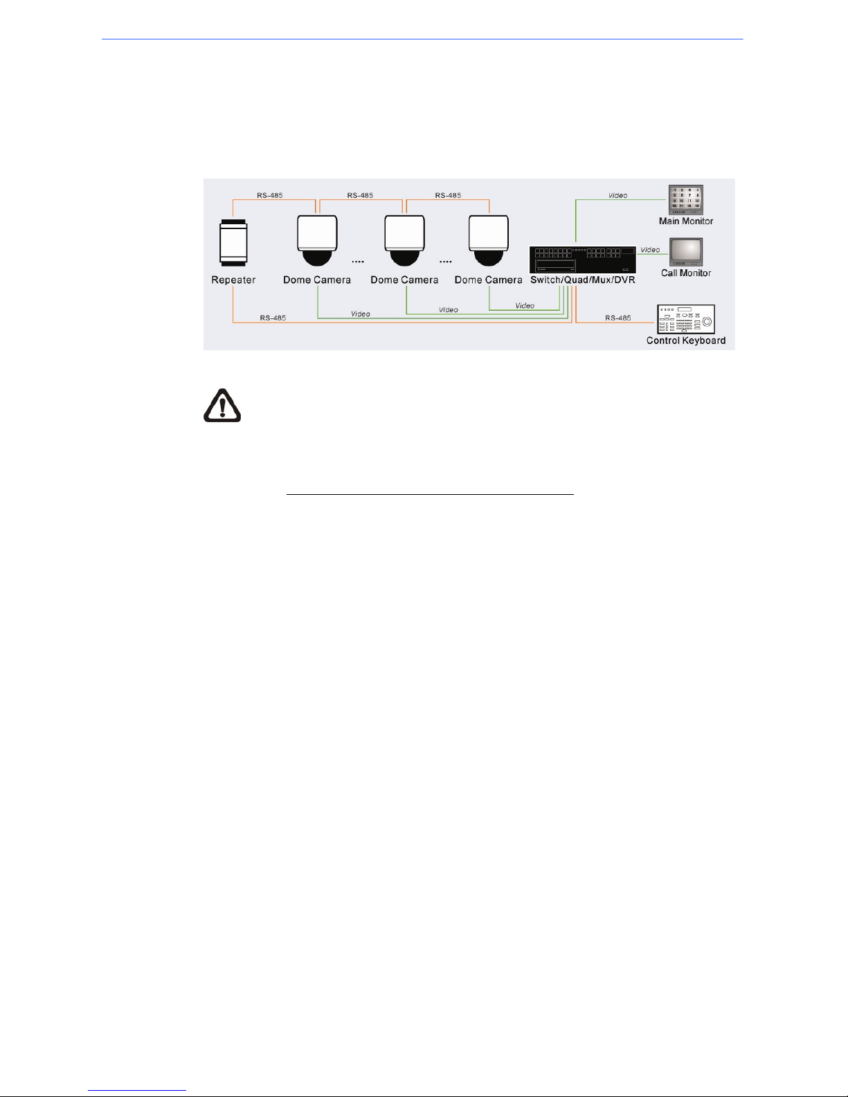
1.2 Product Application
Connect PTZ Cameras to other devices, as shown in the diagram, to
complete a video surveillance solution.
NOTE: To extend the network distance up to 1.2 km (4000 feet) and to
protect the connected devices, it is highly recommended to place a
repeater at the mid-point. However, a repeater may be needed in the network
distance less than 1.2 km if the used cables are not the CAT 5, 24-gauge
cables; see 2.7 RS-485 Connector Definition (Analog)
. Refer to the repeater’s
manual for detailed information.
User’s Manual
10
2. Connecting the Mini PTZ Camera
Please refer to the following sections to connect, set and operate the PTZ
Camera. In order to control the camera, basically a control keyboard or other
control device is required.
2.1 Package Content
Before proceeding, please check the box contains the items listed here. If any
item is missing or has defects, DO NOT install or operate the product and
contact your dealer for assistance.
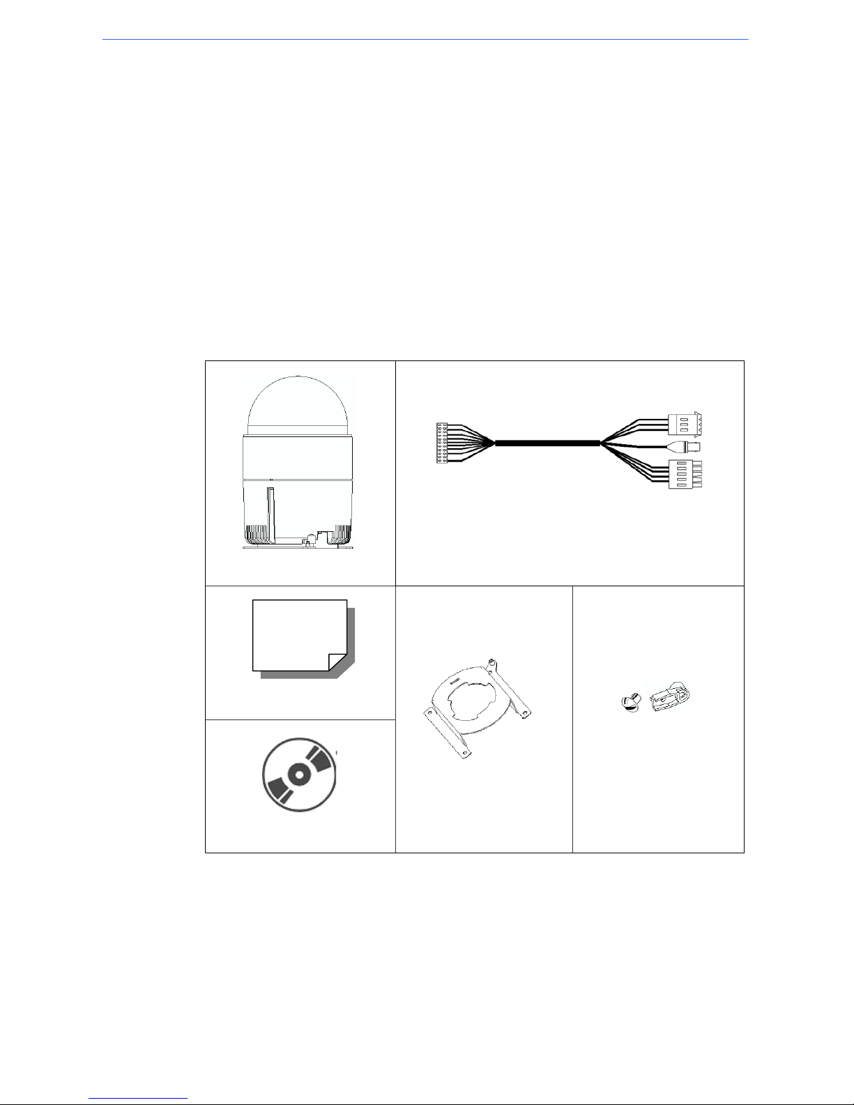
Mini Indoor PTZ Camera Package
PTZ Camera
Data Cable for Power Supply, Video and RS-485
(for AC 24V model)
Quick Guide
CD: Operation Manuals
Hard Ceiling Mount
M3 Screw, Fixing Plate
User’s Manual
11
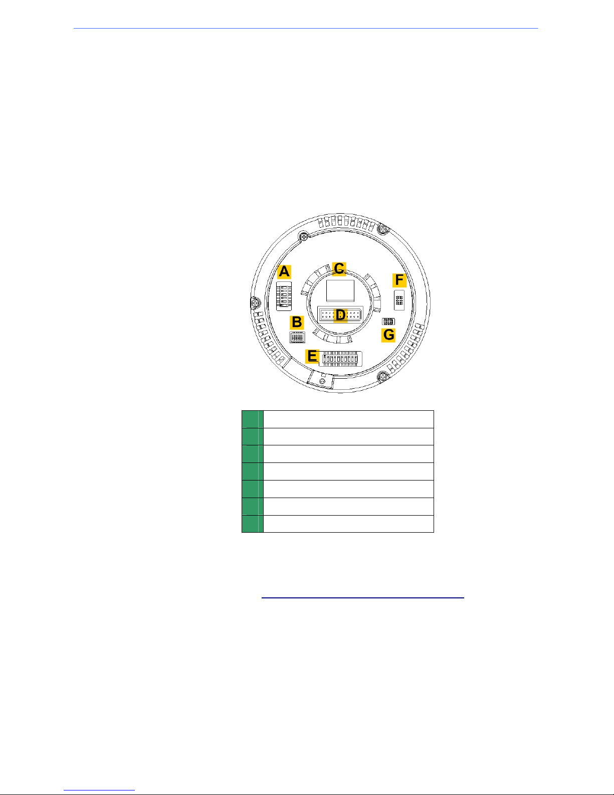
2.2 Switch/Connector Definition
Configuring the PTZ Camera’s ID and communication protocol are required
before connecting the analog camera to other devices. The switches used for
configuring these settings are located on the bottom of the PTZ Camera.
Additionally, the 22-Pin Connector for Data Cable connection and ISP
Connector for firmware upgrade kit connection are located on the back plate
of the PTZ Camera. Please refer to the diagrams and tables accompanied
with for use of each switch/connector.
A
Camera Control Protocol Switch
B
Communication Switch
C
None
D
22-Pin Connector
E
ID Switch
F
Reserved
G
ISP Connector (for FW upgrade)
The ID and Protocol numbers of an analog camera are set with a 10-bit and
6-bit dip switch respectively using binary system. For switch configuration
details, please refer to Appendix B: Switch Settings Index Table.
User’s Manual
12
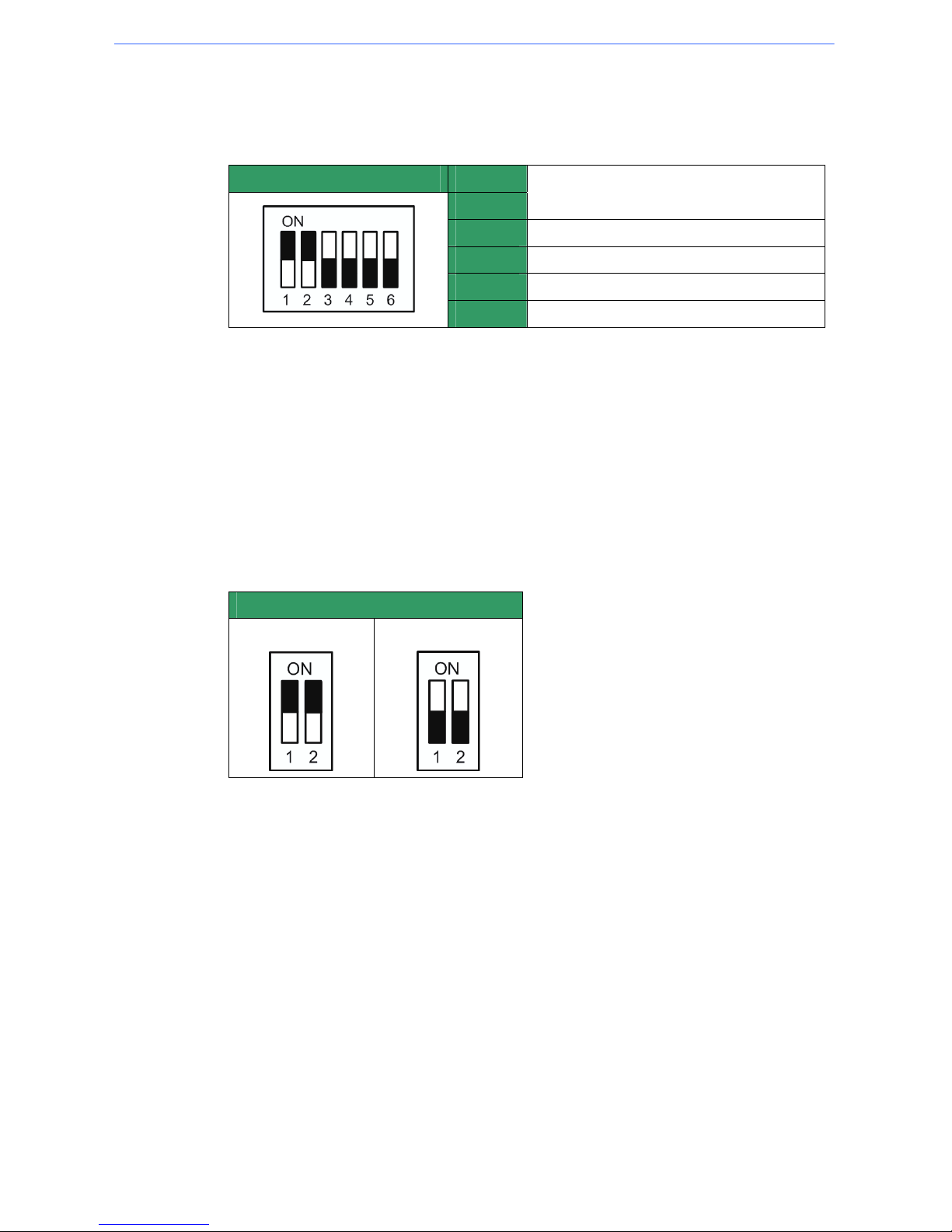
2.3 Communication Switch Setting
The PTZ Camera’s communication switches are specified in the table below.
Communication Switch SW 1
SW 2
RS-485 Setting
SW 3
Termination
SW 4
Line Lock
SW 5
Factory Default Reset
SW 6
Camera Upgrade
RS-485 is the interface that communicates the PTZ Camera and its control
device; for this reason, the RS-485 setup of the PTZ Camera and the control
device must be the same. The RS-485 default setting is half-duplex (see the
diagram follows). Please do not change the default setting without qualified
specialist or supplier’s notice. As for the SW 3 and SW 4, they are used for
termination and Line Lock adjustment respectively. The SW 5 is mainly used
when users want to restore the camera to the factory default status; moreover,
once firmware upgrade is carried out, users need to reset the SW 6 afterward.
RS-485 Setting
Half-duplex
Full-duplex
User’s Manual
13
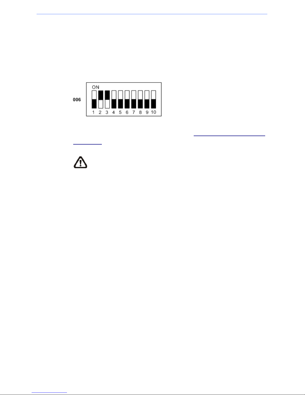
2.4 ID Setup
Please change the PTZ Camera’s ID if there is more than one PTZ Camera in
the same network. Use the switch to change your PTZ Camera’s ID by setting
the 10-bit dip switch. For instance, if the camera’s ID is 006, set the SW-2 and
SW-3 to “ON,” with the rest to “OFF,” as shown below.
For switch configuration details, please refer to Appendix B: Switch Settings
Index Table.
NOTE: No two PTZ Cameras should be given the same ID, or
communication conflict may occur.
User’s Manual
14
2.5 Camera Control Protocol Setup
Define the protocol you are going to use basing on the devices of your
surveillance system. Generally, use one protocol even the devices are
provided from different manufacturers. Please refer to the table below for all
supported protocols with their matching switch numbers and baud rate and
choose a protocol for your PTZ Camera.
Switch No. Protocol Baud Rate
00
VCL 9600
01
Pelco D 2400
02
Pelco P 4800
04
Chiper 9600
05
Philips 9600
07
DSCP 9600
08
AD422 4800
09
DM P 9600
11
Pelco D 4800
12
Pelco D 9600
13
Pelco P 2400
14
Pelco P 9600
15
JVC 9600
21
Kalatel-485 9600
22
Kalatel-422 4800
23
Panasonic 19200
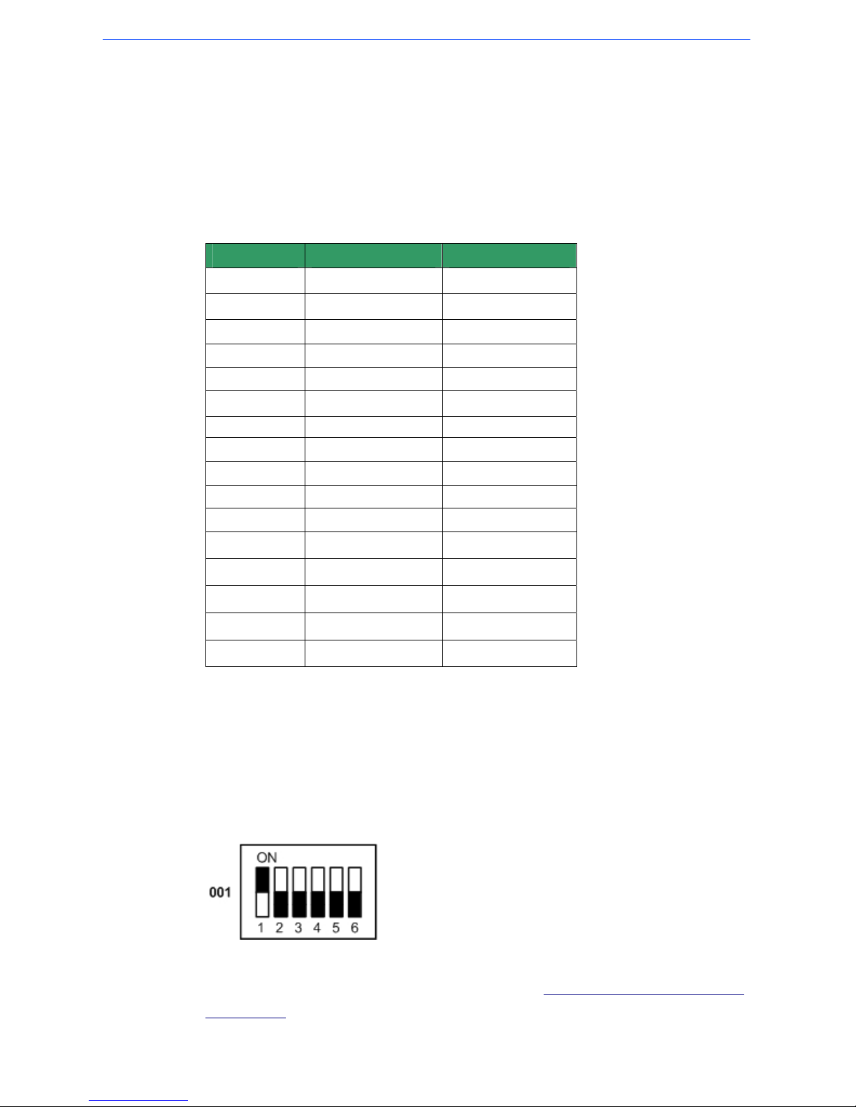
Use the 6-bit dip switch (Camera Control Protocol Switch) to set your
camera’s control protocol and its baud rate.
If select protocol: Pelco D, which is of switch no. 01 and baud rate 2400, for
instance, set the SW-1 to “ON,” with the rest to “OFF,” as shown below.
For switch configuration details, please refer to Appendix B: Switch Settings
Index Table.
User’s Manual
15
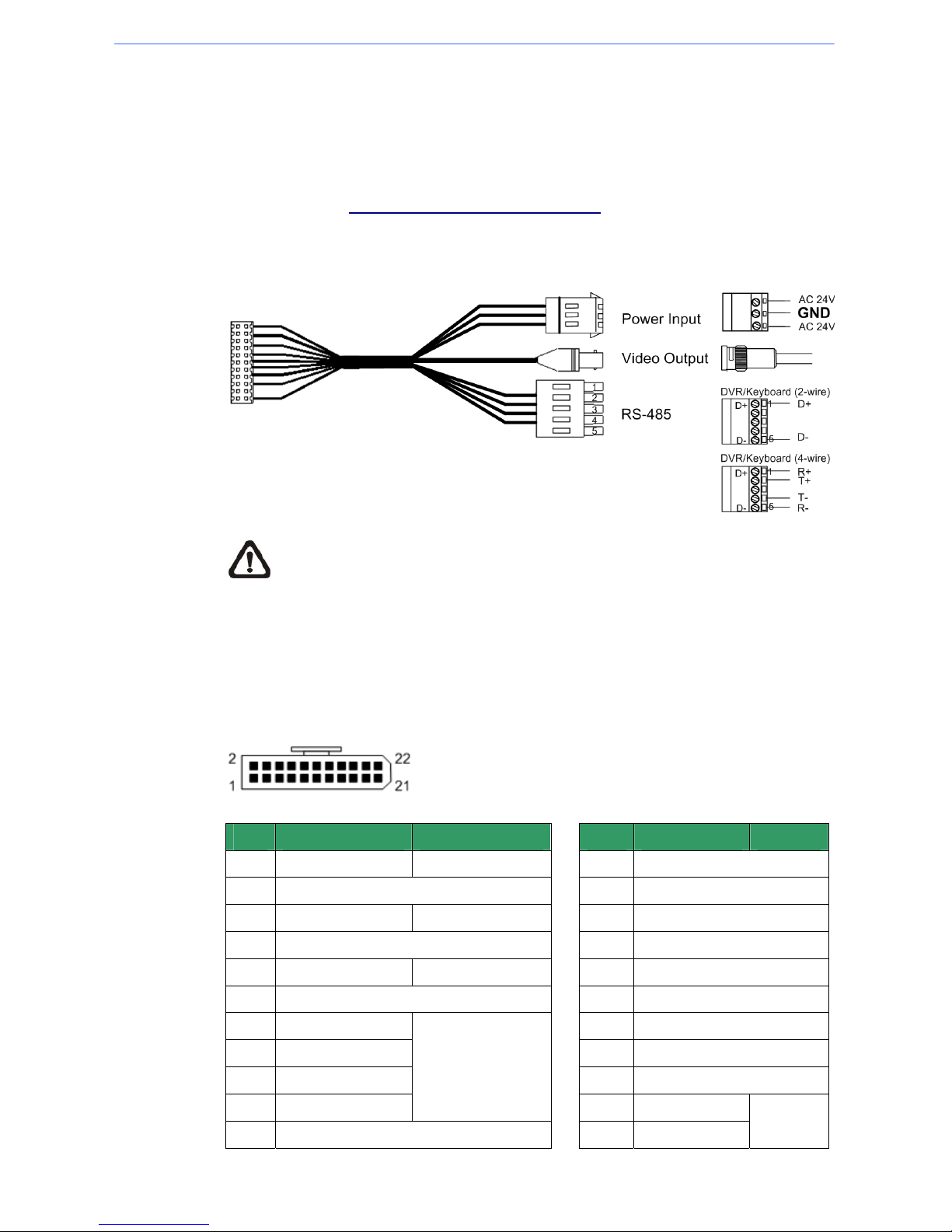
2.6 22-Pin Connector Definition
A Data Cable is shipped with the PTZ Camera for a quick installation for
demo or testing usage. Additionaly, the PTZ Camera’s 22-pin connector
definition will also be specified later. For more information about RS-485
connector, see 2.7 RS-485 Connector Definition.
The PTZ Camera’s Data Cable is illustrated as shown below.
NOTE: Be careful not to pull the cables improperly during installation.
Additionally, it is suggested to fasten the cables after cable connection
is completed. Furthermore, when wiring the AC 24V power cable,
make sure the Ground wire inserted into the mid-pin of the terminal
block.
The PTZ Camera’s 22-pin connector definition is listed as shown below.
Pin Definition Cable
Pin Definition Cable
1
AC 24-1/DC (+)
20AWG/18AWG
12
ALM-1
2
ALM NC
13
ALM-3
3
AC 24-2/DC (-)
20AWG/18AWG
14
ALM-2
4
ALM NO
15
ALM-4
5
FG 20AWG/18AWG
16
ALM-5
6
ALM COM
17
ALM-6
7
T+
18
ALM-7
8
R-
19
ALM-8
9
T-
20
ALM GND
10
R+
24AWG
21
VGND
11
ISOG
22
Video
20AWG

User’s Manual
16
2.7 RS-485 Connector Definition
RS-485 is the interface that communicates the analog PTZ Camera and its
control device. Please connect the control keyboard to the PTZ Camera
through the terminal block. The recommended cables for RS-485
communication are CAT 5 cables; maximum cable length for over 24-gauge
wire is 4000 feet (1219 meters). If the total cable length exceeds 4000 feet,
using a repeater to maintain the signals is recommended. Please refer to the
figure and table below for pin definition and wiring.
Pin
Corresponding Pins
(22-Pin Connector)
Definition
1 7,10 T+, R+ (D+)
2~4 Reserved
5 8,9 T-, R- (D-)

User’s Manual
17
3. Operation and Configuration
3.1 OSD Display Format
Information shown on the screen are described in terms of OSD display,
position and function description; see the table below.
1
2
3
4
56
Position Function OSD Display Description
A Auto Focus Mode
1
Focus Modes
M Manual Focus Mode
X
Back Light Compensation OFF
2
Backlight
B
Back Light Compensation ON
3
Alarm ALARM Alarm Message
4
Zoom Ratio ×1
Present Zoom Ratio
(Optical Zoom/Digital Zoom)
5
Title
• Maximum 20 characters for each title.
• 16 sets of title are available.
6
Camera ID Show the camera ID

User’s Manual
18
3.2 OSD Menu Tree
The OSD setup menu structure is listed in the following section. The star
symbol indicates the factory default. For detailed function description, please
see section 3.3 Configuration Menu.
Mini PTZ Camera Menu Tree
Item Layer 1 Layer 2 Layer 3 Default
LANGUAGE
<ENGLISH>, <PORTUGUESE>, <SPANISH>, <FRENCH>,
<GERMAN>, <ITALIAN>
ENGLISH
DEFAULT
CAMERA
<ON>, <OFF> ON
BACKLIGHT
<ON>, <OFF> OFF
AF MODE <NORMAL>, <Z. TRIG.>, <PTZ TRIG.> AUTO
<AUTO>
EXIT + SAVE: YES
FOCUS
<MANUAL>
<OFF>, EXPOSURE VALUE: <-10.5dB> ~
<10.5dB>
EXPOSURE
COMP.
EXIT + SAVE: YES
BRIGHT VALUE;
SHUTTER SPEED;
IRIS VALUE; GAIN
VALUE: AUTO
AUTO
EXIT + SAVE: YES
SHUTTER SPEED
PAL:<1/50>~
<1/10000> SEC.
NTSC: <1/60>~
<1/10000> SEC.
SHUTTER
EXIT + SAVE: YES
IRIS VALUE <F1.6>
IRIS
EXIT + SAVE: YES
BRIGHT VALUE:
AUTO
SHUTTER SPEED
PAL:<1/50> ~
<1/10000> SEC.
NTSC: <1/60> ~
<1/10000> SEC.
IRIS VALUE <F1.6>
GAIN VALUE
<-3>dB ~ <28>dB
AE MODE
MANUAL
EXIT + SAVE: YES
AE MODE
EXIT+ SAVE: YES
AUTO (Auto White Balance)
☆
INDOOR
OUTDOOR
ATW (Auto-tracing WBC)
R GAIN <000> ~ <127>
B GAIN <000> ~ <127>
WBC MODE
MANUAL
EXIT + SAVE: YES
ZOOM SPEED <8> 8
DIGITAL ZOOM <ON>, <OFF> OFF
SLOW SHUTTER <ON>, <OFF> OFF
2D N.R. <ON>, <OFF> ON
3D N.R. <ON>, <OFF> ON
D.N.R.
EXIT + SAVE: YES
IMAGE INVERSE <ON>, <OFF> OFF
FREEZE <ON>, <OFF> OFF
SETUP MENU 1
ENTER
APERTURE <01> ~ <16> 07

User’s Manual
19
Item Layer 1 Layer 2 Layer 3 Default
EXIT <YES>
<OFF>, <M.E.>,
<IMAGE>
OFF
FLIP
EXIT + SET: YES
ADJUST MIN ANGL
<-10> ~ <+10> DEG
00
ADJUST MAX ANGL
<080> ~ <100> DEG
90
ANGLE ADJUSTER
EXIT + SET: YES
SPEED BY ZOOM <ON>, <OFF> OFF
AUTO CALI. <ON>, <OFF> OFF
PASSWORD <ON>, <OFF> OFF
OSD AUTO CLOSE
<OFF>, <5> ~ <30>
SEC.
20
SYSTEM RESET
<YES>
DEFAULT SYSTEM
<YES>
SYSTEM RESET
EXIT <YES>
SETUP MENU 2
ENTER
EXIT <YES>
ID DISPLAY
<ON>, <OFF> ON
TITLE DISPLAY
<ON>, <OFF> OFF
TITLE SETTING
<01> ~ <16> 01
PRESET SET <001>~<256> ENTER
PRESET RUN <001>~<256> ENTER
PRESET
EXIT YES ENTER
SEQUENCE LINE <1> ~ <8> 1
SEQUENCE POINT <01> ~ <64> 01
PRESET POS.
<001> ~ <255>,
<END>
001
SPEED <01> ~ <15> 01
DWELL TIME <000> ~ <127> SEC. 000
RUN SEQUNECE ENTER
SEQUENCE
ENTER
EXIT <YES>
AUTOPAN LINE <1> ~ <4> 1
START POINT
<TO FIND>,
<TO SAVE>
END POINT
<TO FIND>,
<TO SAVE>
DIRECTION <RIGHT>, <LEFT> Right
SPEED <01> ~ <04> 01
RUN AUTOPAN
AUTOPAN
ENTER
EXIT
CRUISE LINE <1> ~ <8> 1
RECORD START ENTER
RECORD END ENTER
RUN CRUISE ENTER
CRUISE
ENTER
EXIT ENTER
HOME FUNCTION <ON>, <OFF> OFF
PRESET
☆
SEQUENCE
AUTOPAN
SELECT MODE
CRUISE
PRESET POINT
SEQUENCE LINE
AUTOPAN LINE
CRUISE LINE
<001> ~ <256>
<001> ~ <008>
<001> ~ <004>
<001> ~ <008>
001
RETURN TIME <001> ~ <128> MIN. 001
GO ENTER
HOME SETTING
ENTER
EXIT YES
THRESHOLD <MID>, <HI>, <LOW>
AUTO
EXIT + SAVE: YES
IR FUNCTION
MANUAL IR MANUAL: <ON>, <OFF>
AUTO
 Loading...