

Page 1
Page 2

Installation Guide
Preface
The information provided in this manual was current when published. The company reserves the
right to revise and improve its products. All specifications are subject to change without notice.
Notice
To work with the PTZ cameras, any installer or technician must have the following
minimum qualifications:
• A basic knowledge of CCTV systems and components
• A basic knowledge of electrical wiring and low-voltage electrical connections
• Thorough familiarity with the contents of this manual
Important Information
Before proceeding, please read and observe all instructions and warnings in this
manual. Retain this manual with the original bill of sale for future reference and, if
necessary, warranty service. When unpacking your unit, check for missing or
damaged items. If any item is missing, or if damage is evident, DO NOT INSTALL OR
OPERATE THIS PRODUCT. Contact your dealer for assistance.
Copyright
Under copyright laws, the contents of this user manual may not be copied,
photocopied, translated, reproduced or replicated in any electronic medium or
machine-readable format, in whole or in part, without the prior written permission of
CBC Co. Ltd.
©Copyright2006CBC Co. Ltd.
Regulation
This device complies with Part 15 of the FCC Rules. Operation is subject to the
following two conditions:
(1) this device may not cause harmful interference, and (2) this device must accept
any interference received, including interference that may cause undesired
operation.
1
Page 3

Installation Guide
English
Disposal of your old appliance
1. When this crossed-out wheeled bin symbol is attached to a product it means the
product is covered by the European Directive 2002/96/EC.
2. All electrical and electronic products should be disposed of separately from the
municipal waste stream via designated collection facilities appointed by the
government or the local authorities.
3. The correct disposal of your old appliance will help prevent potential negative
consequences for the environment and human health.
4. For more detailed information about disposal of your old appliance, please contact
your city office, waste disposal service or the shop where you purchased the
product.
Français/French
Élimination de votre ancien appareil
1. Ce symbole, représentant une poubelle sur roulettes barrée d'une croix, signifi e
que le produit est couvert par la directive européenne 2002/96/EC.
2. Tous les produits électriques et électroniques doivent être éliminés séparément
de la chaîne de collecte municipale des ordures, par l’
intermédiaire des installations de collecte prescrites et désignées par le
gouvernement ou les autorités locales.
3. Une élimination conforme aux instructions aidera à réduire les conséquences
negatives et risqueséventuelspour l'environnement et la
santé humaine.
4. Pour plus d'informations concernant l'élimination de votre ancien appareil, veuillez
contacter votre mairie, le service des ordures ménagères ou encore le magasin où
vous avez acheté ce produit.
2
Deutsch/German
Entsorgung von Altgeräten
1. Wenn dieses Symbol eines durchgestrichenen Abfalleimers auf einem Produkt
angebracht ist, unterliegt dieses Produkt der europäischen Richtlinie 2002/96/EC.
2. Alle Elektro- und Elektronik-Altgeräte müssen getrennt vom Hausmüll über die
dafür staatlich vorgesehenen Stellen entsorgt werden.
3. Mit der ordnungsgemäßen Entsorgung des alten Geräts vermeiden Sie
Umweltschäden und eine Gefährdung der persönlichen Gesundheit.
Page 4

Installation Guide
4. Weitere Informationen zur Entsorgung des alten Geräts erhalten Sie bei der
Stadtverwaltung, beim Entsorgungsamt oder in dem Geschäft, wo Sie das Produkt
erworben haben.
Italiano/Italian
INFORMAZIONE AGLI UTENTI
Ai sensi dell’art. 13 del Decreto Legislativo 25 luglio 2005, n. 151 "Attuazione delle
direttive 2002/95/CE, 2002/96/CE e 2003/108/CE, relative alla riduzione dell'uso di
sostanze pericolose nelle apparecchiature elettriche ed elettroniche, nonché allo
smaltimento dei rifiuti"
Il simbolo del cassonetto barrato riportato sull’ apparecchiatura o sulla sua
confezione indica che il prodotto alla fi ne della propria vita utile deve essere raccolto
separatamente dagli altri rifiuti.
La raccolta differenziata della presente apparecchiatura giunta a fi ne vita è
organizzata e gestita dal produttore. L’utente che vorrà disfarsi della presente
apparecchiatura dovrà quindi contattare il produttore e seguire il sistema che questo
ha adottato per consentire la raccolta separata dell'apparecchiatura giunta a fi ne
vita.
L’adeguata raccolta differenziata per l’avvio successivo dell’apparecchiatura
dismessa al riciclaggio, al trattamento e allo smaltimento ambientalmente
compatibile contribuisce ad evitare possibili effetti negativi sull’ambiente e sulla
salute e favorisce il reimpiego e/o il riciclo dei materiali di cui è composta
l’apparecchiatura.
Lo smaltimento abusivo del prodotto da parte del detentore comporta l’applicazione
delle sanzioni amministrative previste dalla normativa vigente.
Polski/Polish
Utylizacja starych urządzeń
1. Kiedy do produktu dołączony jest niniejszy przekreślony symbol kołowego
pojemnika na śmieci, oznacza to, że produkt jest objęty europejską dyrektywą
2002/96/EC.
2. Wszystkie elektryczne i elektroniczne produkty powinny być utylizowane
niezależnie od odpadów miejskich, z wykorzystaniem przeznaczonych do tego
miejsc składowania wskazanych przez rząd lub miejscowe władze.
3. Właściwy sposób utylizacji starego urządzenia pomoże zapobiec potencjalnie
negatywnemu wpływowi na zdrowie i środowisko.
4. Aby uzyskać więcej informacji o sposobach utylizacji starych urządzeń, należy
skontaktować się z władzami lokalnymi, przedsiębiorstwem zajmującym się
utylizacją odpadów lub sklepem, w którym produkt został kupiony.
3
Page 5

Installation Guide
Português/Portuguese
Eliminação do seu antigo aparelho
1. Quando este símbolo de latão cruzado estiver afi xado a um produto, signifi ca
que o produto é abrangido pela Directiva Europeia 2002/96/EC.
2. Todos os produtos eléctricos e electrónicos devem ser eliminados
separadamente da coleta de lixo municipal através de pontos de recolha designados,
facilitados pelo governo ou autoridades locais.
3. A eliminação correcta do seu aparelho antigo ajuda a evitar potenciais
consequências negativas para o ambiente e para a saúde humana.
4. Para obter informaçõs mais detalhadas acerca da eliminação do seu aparelho
antigo, contacte as autoridades locais, um service de eliminação de resíduos ou a
loja onde comprou o produto.
Español/Spanish
Cómo deshacerse de aparatos
eléctricos y electrónicos viejos
1. Si en un producto aparece el símbolo de un contenedor de basura tachado, signifi
ca que éste se acoge a la Directiva 2002/96/EC.
2. Todos los aparatos eléctricos o electrónicos se deben desechar de forma distinta
del servicio municipal de recogida de basura, a través de puntos de recogida
designados por el gobierno o las autoridades locales.
3. La correcta recogida y tratamiento de los dispositivos inservibles contribuye a
evitar riesgos potenciales para el medio ambiente y la salud pública.
4. Para obtener más información sobre cómo deshacerse de sus aparatos eléctricos
y electrónicos viejos, póngase en contacto con su ayuntamiento, el servicio de
recogida de basuras o el establecimiento donde adquirió el producto.
Русско/Russian
Избавление вашего старого прибора
Этот символ на продукте или его упаковке означает, что данный продукт
нельзя подвергать утилизации вместе с бытовыми отходами в соответствии с
Директивой 2002/96/EC. Его нужно передать в соответствующий пункт сбора
4
для переработки электрического и электронного оборудования. Должная
переработка этого продукта позволит обеспечить отсутствие негативных
последствий для окружающей среды
возникнуть при выбрасывании продукта в мусорную корзину. Переработка
материалов позволяет сохранять природные ресурсы.
Для получения подробных сведений о переработке этого продукта обратитесь
в городской офис компании, службу ликвидации бытовых отходов или магазин,
где был приобретен продукт.
и человеческого здоровья, которые могут
Page 6

Installation Guide
Cautions
• Handle the camera carefully
Do not abuse the camera. Avoid striking, shaking, etc. The camera could be
damaged by improper handing or storage.
• Do not disassemble the camera
To prevent electric shock, do not remove screws or covers. There are no user
serviceable parts inside. Ask a qualified service person for servicing.
• Do not block cooling holes on the bracket
This camera has a cooling fan inside. Blocking the cooling holes leads to build up
of heat the camera and may cause malfunction.
• Do not operate the camera beyond the specified temperature, humidity or
power source ratings
Use the indoor camera under conditions where temperature is between 0~40°C
(32~104°F), outdoor camera between -50~50°C (-58~122°F), and humidity is
below 90%.
• Do not use strong or abrasive detergents when cleaning the camera body
Use a dry cloth to clean the camera when dirty. In case the dirt is hard to remove,
use a mild detergent and wipe gently.
• Never face the camera towards the sun
Do not aim the camera at bright objects. Whether the camera is in use or not,
never aim it at the sun or other extremely bright objects. Otherwise, the camera
may be smeared or damaged.
5
Page 7

Installation Guide
Table of Contents
1. Introduction ............................................................................................................................. 8
2. Package Content................................................................................................................... 10
3. PTZ Camera Setups and Cable Connections ..................................................................... 12
3.1 Preparations for PTZ Camera Setups (Indoor Camera) ..................................12
3.2 Preparations for PTZ Camera Setups (Outdoor Camera)................................12
3.3 PTZ Camera Setups ........................................................................................15
3.3.1 Switch Definition ..................................................................................15
3.3.2 Communication Switch Setting ............................................................15
3.3.3 PTZ Camera ID Setting .......................................................................16
3.3.4 PTZ Camera Control Protocol .............................................................16
3.4 Cables and Connections..................................................................................18
3.4.1 Cable Requirements............................................................................18
3.4.2 22-Pin Data Cable ...............................................................................18
3.4.3 22-Pin Connector Definition.................................................................19
3.4.4 RS-485 Connector Definition ...............................................................20
3.5 Cable Wiring and Connection ..........................................................................21
4. PTZ Camera Installation ....................................................................................................... 22
4.1 PTZ Camera Dimension ..................................................................................22
4.2 Optional Accessories .......................................................................................23
4.3 Ceiling Mount...................................................................................................31
4.3.1 Hard-Ceiling Mounting / Indoor............................................................32
4.3.2 In-Ceiling Mounting / Indoor.................................................................34
4.3.3 In-Ceiling Mounting with Ceiling Panel ................................................37
4.3.4 Ceiling Mounting with Straight Tube (ZCA-ST25/ST50) ......................37
4.4 Wall Mount.......................................................................................................41
4.4.1 Mini Pendant Mount (ZCA-GT100) ......................................................41
4.4.2 Standard Pendent Mount.....................................................................45
4.4.3 Wall Box Mounting (ZCA-WBM) ..........................................................48
4.5 Corner Mount...................................................................................................51
4.5.1 Standard/Mini Corner Mounting Plate (ZCA-CST/MCP)......................51
4.5.2 Corner Thin/Wide Box Mounting (ZCA-CTB/CWB) .............................54
4.6 Pole Mount ......................................................................................................57
4.6.1 Pole Thin/Wide Direct Mounting (ZCA-PTDM/PWDM) ........................57
4.6.2 Pole Thin/Wide Box Mounting (ZCA-PTB/PWB)..................................60
5. System Expansion ................................................................................................................63
5.1 Connecting with Connector Box (Indoor Use)..................................................63
5.2 Connecting with Power Box.............................................................................64
5.3 Repeater Application .......................................................................................65
5.4 RS485 Distribution Unit (ZCA-DS4/8/16).........................................................66
6
Page 8

Installation Guide
6. System Integration................................................................................................................ 67
6.1 Using Pelco Keyboard .....................................................................................67
6.2 Using Phillips Allegiant Keyboard ....................................................................69
Appendix A: Technical Specification.......................................................................................... 71
7
Page 9

1. Introduction
ZC-PT series integrated indoor PTZ Camera is a new subcompact designed to
deliver superb performance and durability with an intelligent and stylish housing that
is suitable in any security and surveillance installation. ZC-PT-XT series is a new
weather resistant integrated outdoor PTZ Camera. Both ZC-PT and ZC-PT-XT
series PTZ Cameras support one cabling for easy installation, and can be integrated
with CCTV products, such as DVRs, Control Keyboards, and CCTV accessories for
a total surveillance solution.
The PTZ Camera provides four models of new generation advanced DSP color
camera:
z ZC-PT236 Model: 36× optical zoom / 12× digital magnification
z ZC-PT235 Model: 35× optical zoom / 12× digital magnification
z ZC-PT230 Model: 30× optical zoom / 12× digital magnification
Installation Guide
z ZC-PT226 model: 26× optical zoom / 12× digital magnification
z ZC-PT218 model: 18× optical zoom / 12× digital magnification
General Operation Requirements:
A minimum of one control device is required for operation, such as a control
keyboard, a DVR or a PC. The integrated high speed dome camera contains a
built-in receiver that decodes commands originating from a control device.
The PTZ Camera supports one cabling for easy installation. Large set of built-in
protocols, including GANZ, Pelco, VCL, Philips, AD-422 (Manchester), etc, which
allow the PTZ Camera to be integrated with other suppliers' surveillance systems.
8
Page 10
Installation Guide
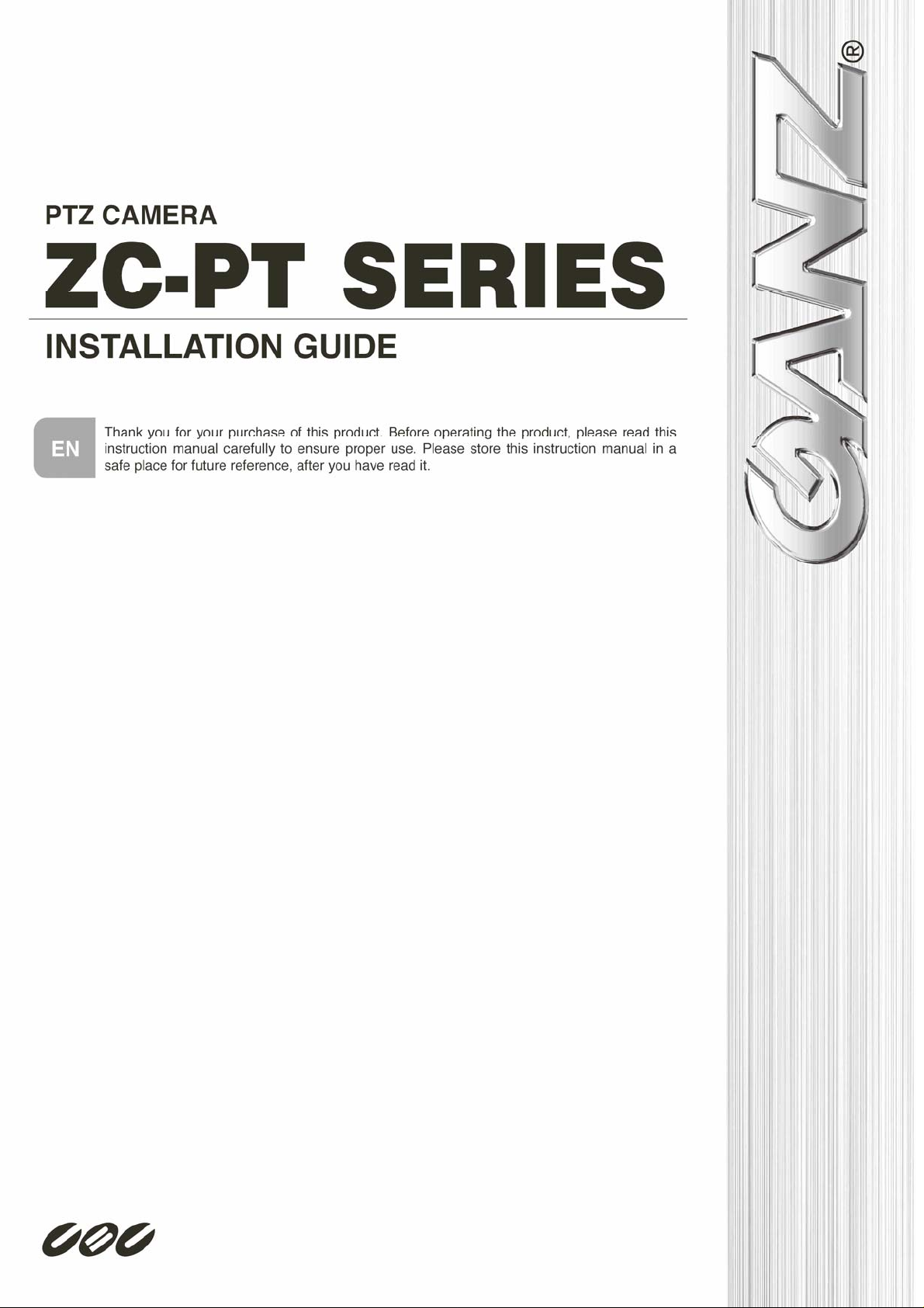
Connect the PTZ Camera to other devices as shown in the diagram to complete a
video surveillance solution.
NOTE: To extend the network distance up to 1.2 km (4000 feet) and to
protect the connected devices, it is highly recommended to place a repeater
at the mid-point. However, a repeater may be needed in the network distance less
than 1.2 km if the used cables are not the CAT 5, 24-gauge cables (see 3.4.4
RS-485 Connector Definition). Refer to the repeater user manual for detailed
information.
9
Page 11
2. Package Content
Before proceeding, please check the box contains the items listed here. If any item is
missing, or if damage is evident, DO NOT install or operate the product and contact
your dealer for assistance.
Installation Guide
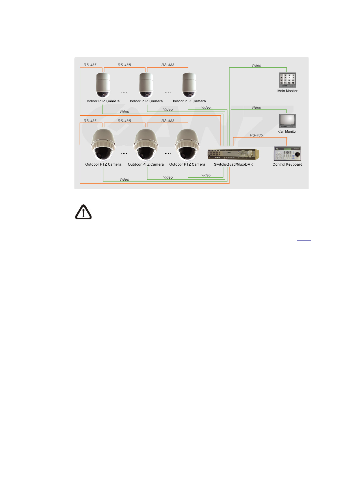
Indoor PTZ Camera Standard Package
Camera Body
Hard Ceiling Mount
and Decoration Ring
Cable for Power,
Video, RS-485
and Alarm
Power Cord
Fixing Plate
Installation Guide
& Quick Guide
Optical Cover
CD
10
Page 12
Installation Guide
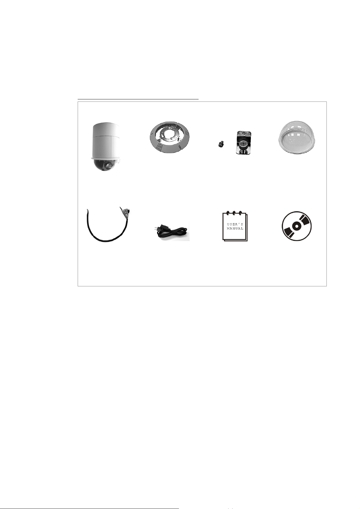
Outdoor PTZ Camera Standard Package
Camera Body with
Outdoor Mount Kit
Lubricant
CD
Screws
Cable for Power,
Video, RS-485
and Alarm
Security screw
set
Power Cord
Water-proof rubber
Installation Guide
& Quick Guide
11
Page 13
Installation Guide
3. PTZ Camera Setups and Cable Connections
Before installing or connecting the PTZ Camera, please refer to this section and
complete preparations for camera setups and various switch setting.
3.1 Preparations for PTZ Camera Setups (Indoor Camera)
There will be a PE cloth sheet covered inside the camera cover and a lens cap on
the lens for shipping protection. Follow the steps below to remove those protective
materials.
Step 1: Unpack the PTZ Camera’s package and take out the camera body.
Step 2: Rotate the dome cover.
Step 3: Remove the PE cloth sheet and take off the lens cap.
Step 4: Replace the dome cover back.
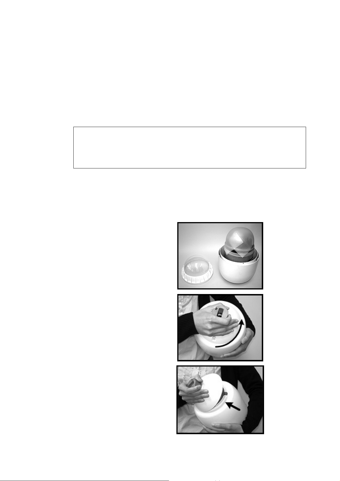
3.2 Preparations for PTZ Camera Setups (Outdoor Camera)
This installation procedure is for the outdoor camera equipped with sunshield
housing. Please follow the steps below to complete camera housing installation.
STEP 1
Unpack the standard camera
package and take out the camera.
STEP 2
Rotate the Outdoor Mount Kit,
and take it off from the camera
body.
12
Page 14
Installation Guide
STEP 3
Remove the protective cover and
PE cloth.
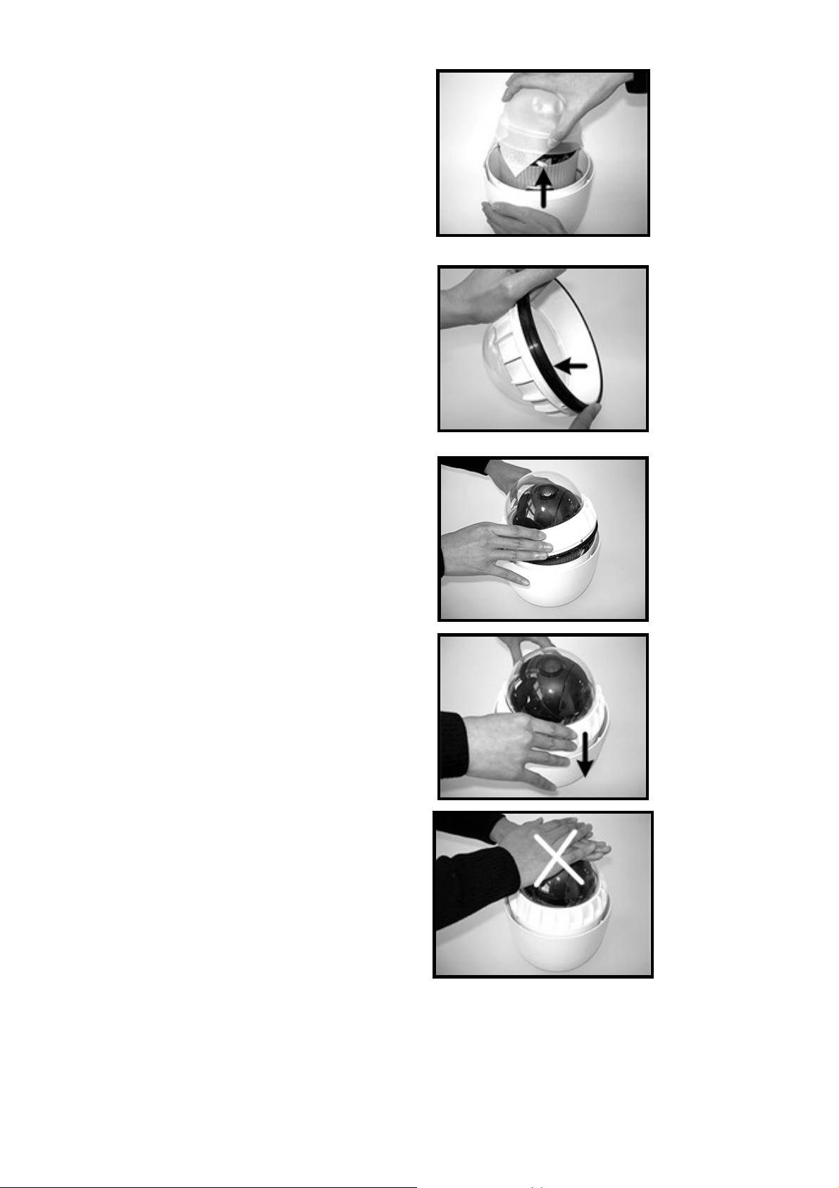
STEP 4
Attach the camera cover to the
camera body. Before doing that,
apply some lubricant on the
cover’s water-proof rubber to
make the installation process
smoother.
Note that the tiny protrusion on
the camera cover must align with
one of the four holes on the
camera body.
STEP 5
Gently pressure the camera cover
downward with two hands on the
side of it.
DO NOT press the cover as
shown in the figure; this might
cause damage to the camera
body.
13
Page 15

STEP 6
Screw the camera cover and
body together.
Installation Guide
STEP 7
Set the switches located on the
bottom of the camera body. Refer
to section 3.3 PTZ Camera
Setups for detailed information
about various switch setting.
14
Page 16
Installation Guide
3.3 PTZ Camera Setups
Before connecting the camera to other devices of CCTV system, please complete
the camera ID and communication switch setting. These switches are located on the
bottom of the camera.
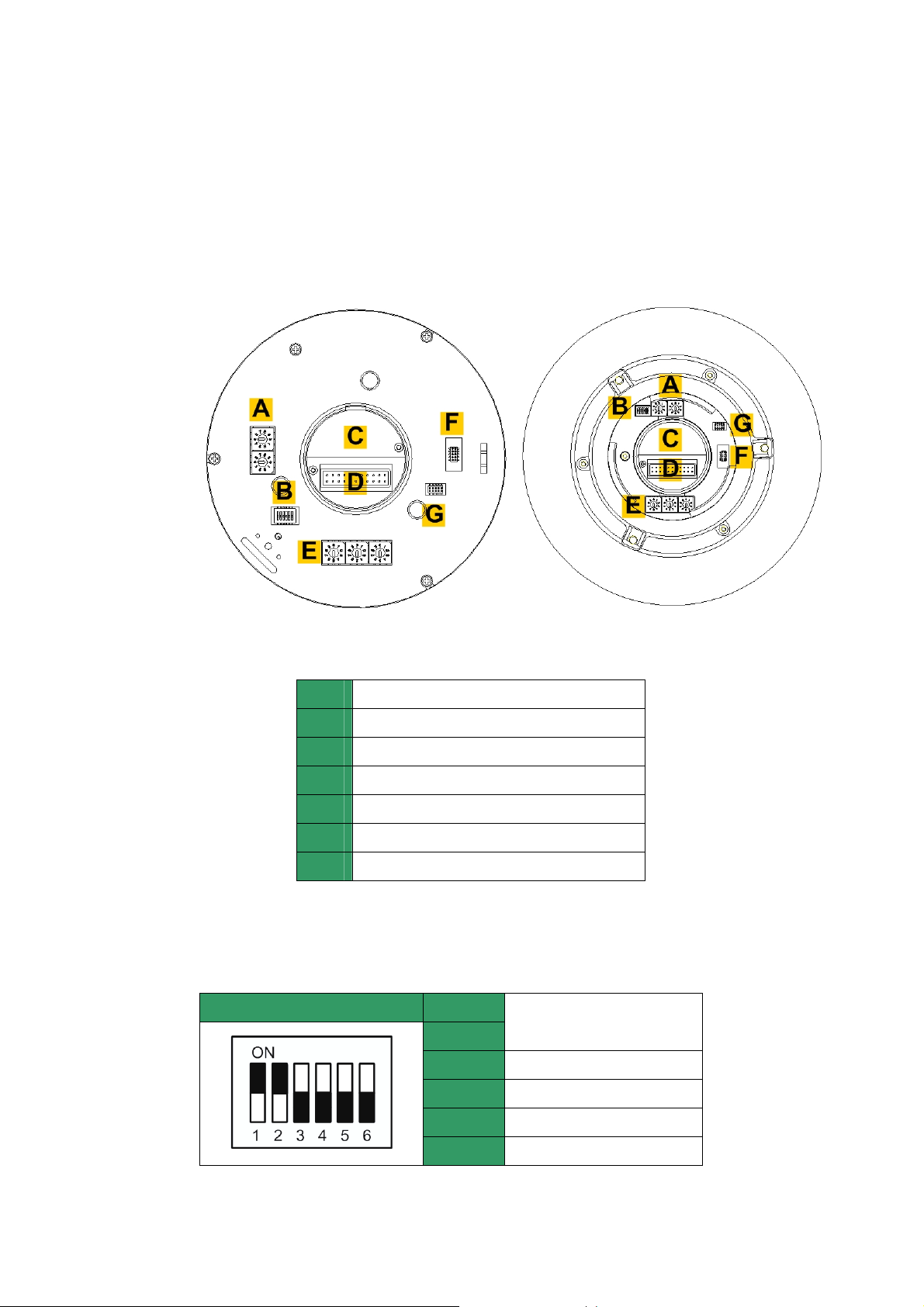
3.3.1 Switch Definition
Please refer to the following figures and table for switch location and definitions.
Indoor PTZ Camera Outdoor PTZ Camera
Camera Control Protocol Switch
A
Communication Switch
B
None
C
22-Pin Connector
D
ID Switch
E
Reserved
F
ISP Connector (for FW upgrade)
G
3.3.2 Communication Switch Setting
The table below shows the function of each switch within the Communication Switch.
Communication Switch SW 1
SW 2
RS-485 Setting
SW 3
SW 4
SW 5
SW 6
Termination
Line Lock
Factory Default Reset
Reserved
15
Page 17
Installation Guide
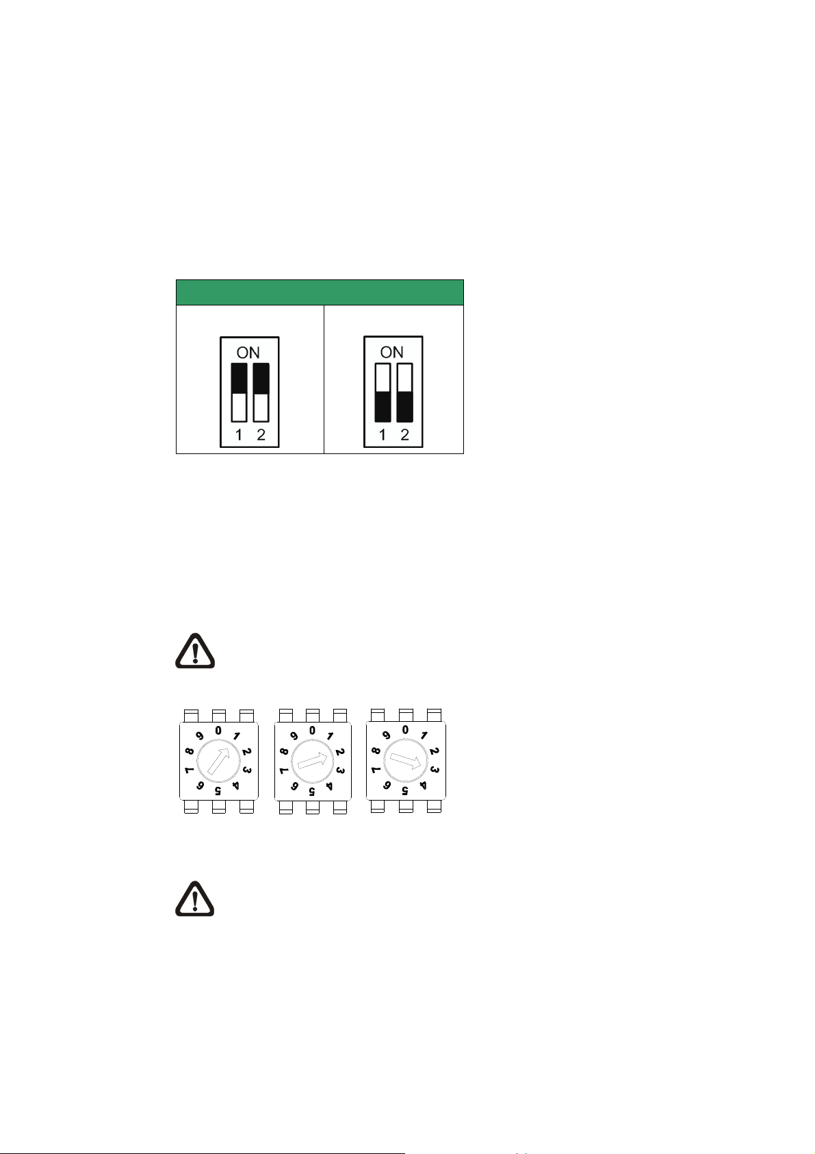
RS-485 is the interface that communicates the PTZ Camera and its control device;
for this reason, the RS-485 setup of the PTZ Camera and the control device must be
the same. The RS-485 default setting is half-duplex (see the diagram follows).
Please do not change the default setting without qualified specialist or supplier’s
notice. As for the SW 3 and SW 4, they are used for termination and Line Lock
adjustment respectively. The SW 5 is mainly used when users want to restore the
PTZ Camera to the factory default status; moreover, once firmware upgrade is
carried out, users also need to reset the SW 5 afterward.
RS-485 Setting
Half-duplex
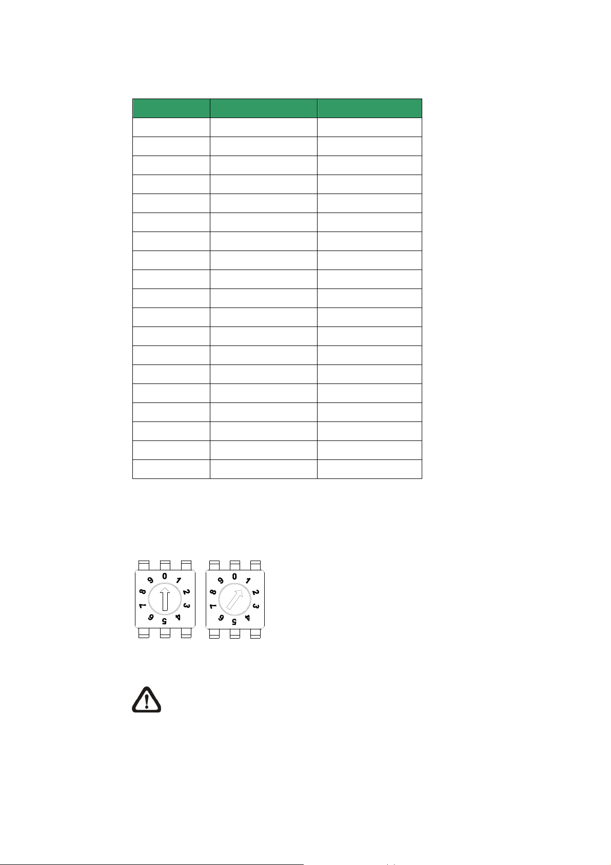
3.3.3 PTZ Camera ID Setting
Please change the camera ID if there is more than one camera on the same
installation site. To change your camera ID, please turn the arrow of the ID switch to
a desired number respectively. For instance, if the camera ID is 123, the ID switch
should be set as below.
NOTE: No two cameras should be given the same ID, or communication
conflict may occur.
The default camera ID is “001”.
Full-duplex
Hundreds Tens Units
NOTE: The number “0” should locate upwards as shown in above diagram
for correct switch definition.
3.3.4 PTZ Camera Control Protocol
Protocol is a specific set of rules, procedures used for data communications. Basing
on the devices of your surveillance system and define the protocol you are going to
use. Generally, use one protocol even the devices are provided from different
manufacturers. Use the switch to set your PTZ Camera control protocol and the
16
Page 18
Installation Guide
baud rate. Refer to below table and turn the arrow to choose a protocol for your
camera.
Switch No. Protocol Baud Rate
00
01
02
04
05
07
08
09
11
12
13
14
15
16
17
18
VCL 9600
Pelco D 2400
Pelco P 4800
Chiper 9600
Philips 9600
GANZ-PT 9600
AD422 4800
DM P 9600
Pelco D 4800
Pelco D 9600
Pelco P 2400
Pelco P 9600
JVC 9600
GANZ-S 4800
GANZ-S 9600
GANZ-S 19200
19
21
22
GANZ-S 38400
Kalatel-485 9600
Kalatel-422 4800
Select protocol: Pelco D with Baud rate 2400, for instance, the protocol switch should
be set as below.
Tens Units
NOTE: The number “0” should locate upwards as shown in above diagram
for correct switch definition.
17
Page 19
3.4 Cables and Connections
The PTZ Camera is supplied with one integrated 22-pin Data Cable for connecting
with the power, video, and RS-485/audio input & audio output cables. Please read
the following sections thoroughly before making connections.
3.4.1 Cable Requirements
For operation, the PTZ Camera requires video, RS-485 and power cables as
described below:
• The video cable sends video signals to a remote viewing site. Using a coaxial
cable to send video signals is recommended.
• RS-485 cable carries commands from a control device to the dome cameras. A
CAT 5, 24 gauge cable is recommended.
• Power supply: AC 24V output voltage
NOTE: Ensure power supply meets the PTZ Camera’s power requirement,
Installation Guide
or product impairment will occur. If any mistake happens, please contact with
a qualified maintenance engineer.
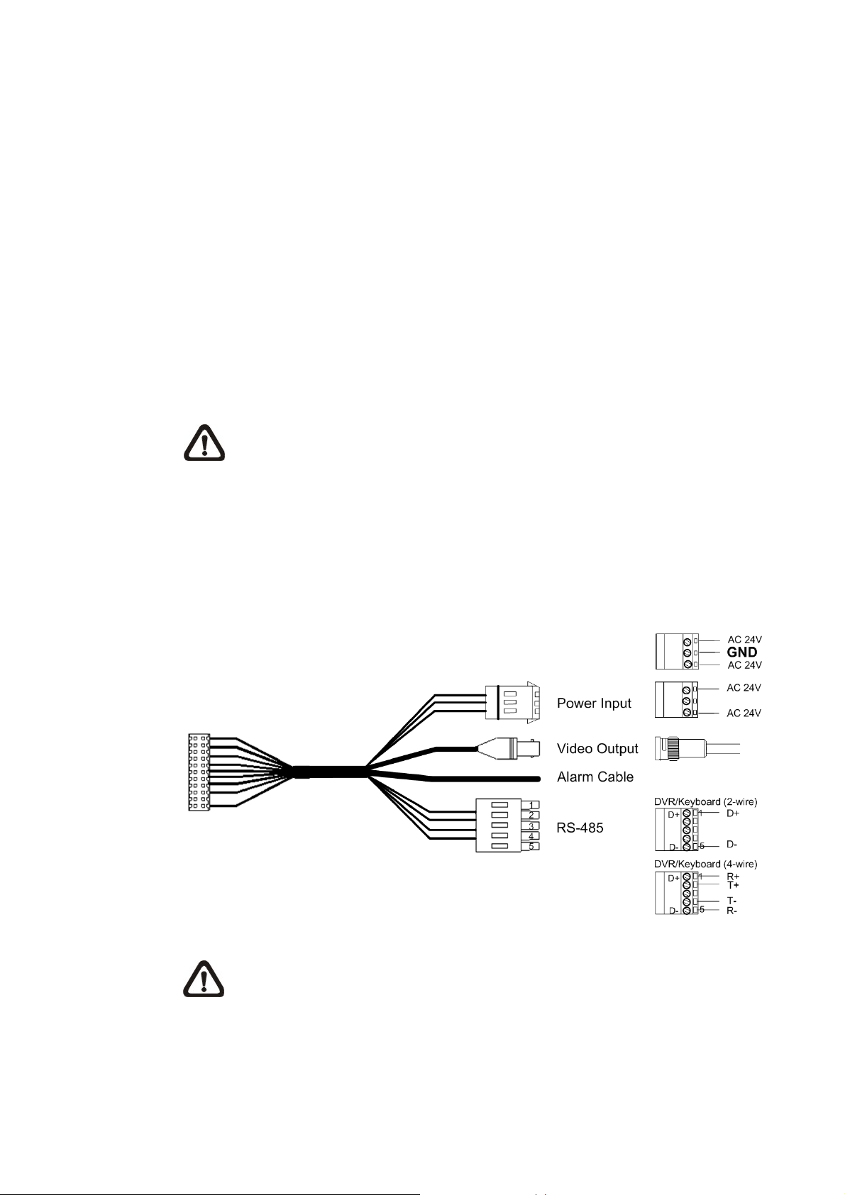
3.4.2 22-Pin Data Cable
A data cable (see the figure below) is shipped with the PTZ Camera for quick
installation for demo or testing usage.
18
NOTE: If the power lines use three wires, make sure the Ground wire is
inserted into the mid-pin of the terminal block as shown in the figure above.
Page 20
Installation Guide
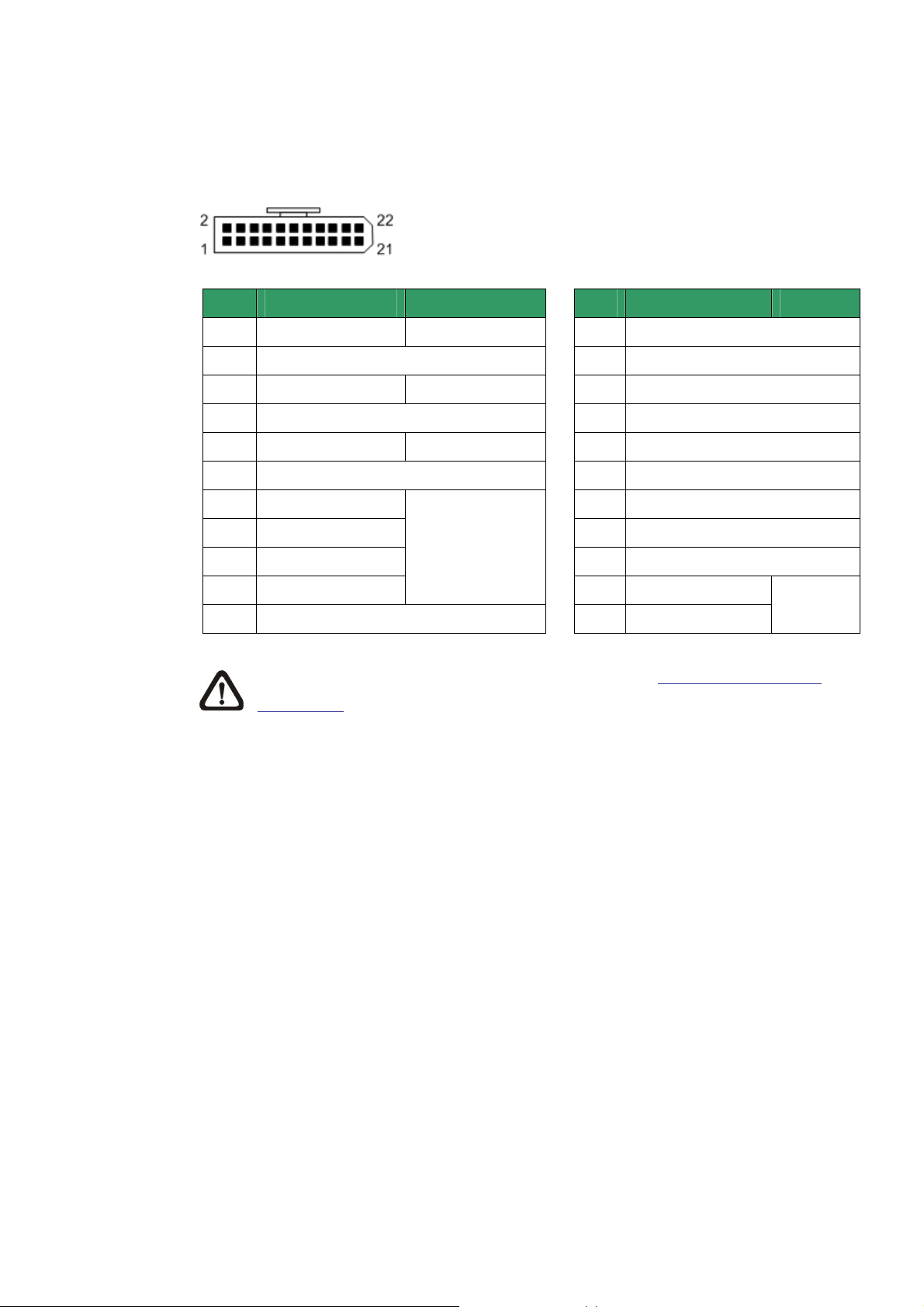
3.4.3 22-Pin Connector Definition
With the 22-pin connector, installers can simply connect the power, video and
RS-485 cables to the camera at once. For the definition of each pin, please refer to
the list below.
Pin Definition Cable
AC 24-1
1
ALM NC
2
3
AC 24-2 20AWG/18AWG
ALM NO
4
5
FG 20AWG/18AWG
ALM COM
6
7
T+
8
R-
20AWG/18AWG
24AWG
9
T-
10
R+
Alarm ISOG
11
NOTE: For alarm connection, please refer to section 3.5 Cable Wiring and
Connection.
Pin
12
13
14
15
16
17
18
19
20
21
22
Definition Cable
ALM-1
ALM-3
ALM-2
ALM-4
ALM-5
ALM-6
ALM-7
ALM-8
ALM GND
VGND
Video
20AWG
19
Page 21
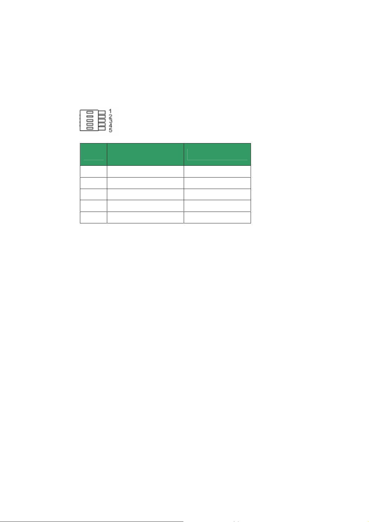
3.4.4 RS-485 Connector Definition
RS-485 is the interface that communicates the camera and its control device. Please
connect the control keyboard to the speed dome through the terminal block. The
recommended cables for RS-485 communication are CAT 5 cables; maximum cable
length for over 24-gauge wire is 4000 feet (1219 meters). If the total cable length
exceeds 4000 feet, using a repeater to maintain the signals is recommended. Please
refer to the figure and table below for pin defination and wiring.
Pin
Corresponding Pins
(22-Pin Connector)
1 7,10 T+, R+ (D+)
2 Reserved
3 Reserved
4 Reservied
5 8,9 T-, R- (D-)
Installation Guide
Definition
20
Page 22
Installation Guide
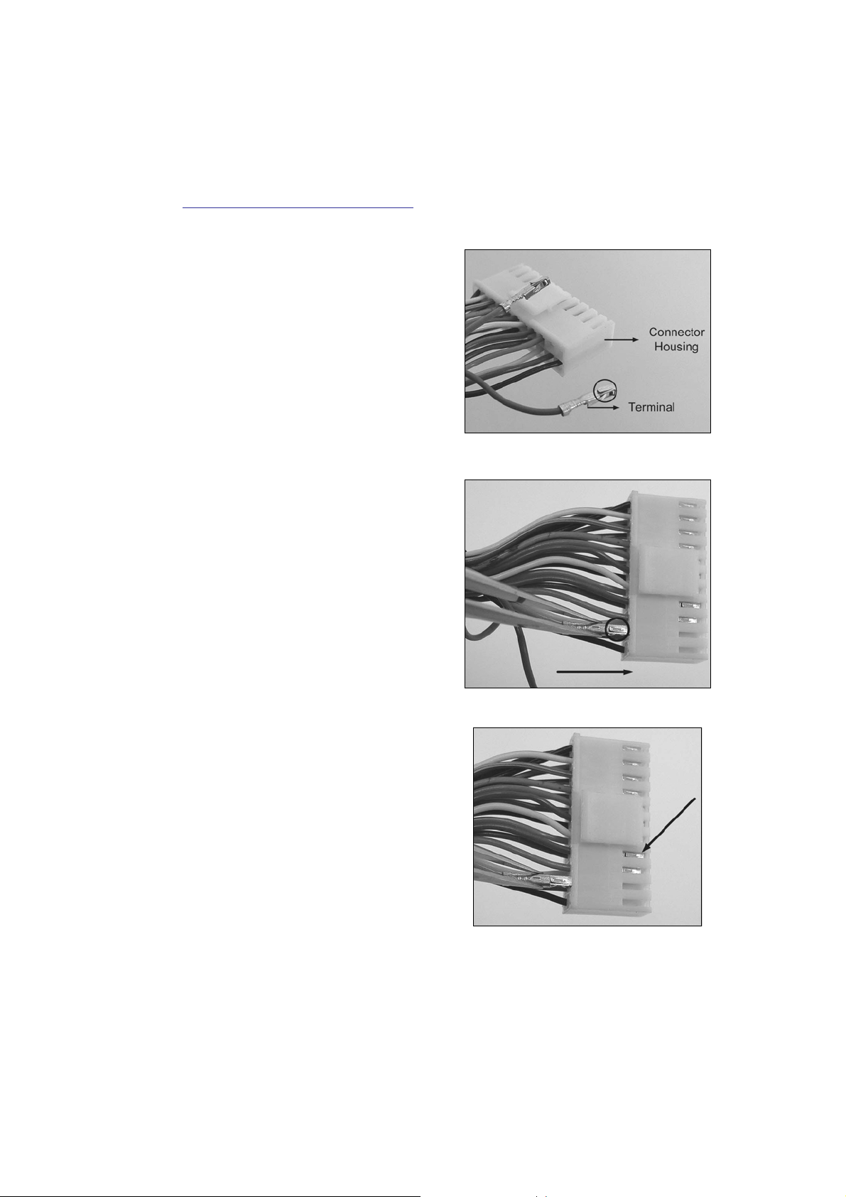
3.5 Cable Wiring and Connection
Users may need to conduct cable wiring when: (1) Connecting self-provided cords to
the connector housing (shown in the figure below) instead of using the equipped
data cable or (2) Connecting alarm input and output devices. The table follows will
illustrate the way to wire cords into the connector housing. Please refer to the section
3.4.3 22-Pin Connector Definition
for the exact position of each cord.
Insert the terminal into the pin holes
on the connector housing, with the
hook outward, as indicated in the
figure.
To unlock the terminal, press the
hook, as indicated in the figure, with a
proper tool and pull it out gently.
Connect the 22-pin connector to the socket on the PTZ Camera’s back plate.
21
Page 23
4. PTZ Camera Installation
Basing on different installation environments, both of the Indoor and Outdoor PTZ
Camera can be installed on ceiling, on wall or on pole. In the following sections,
various installation accessories, installation methods and installation procedures will
be described in detail.
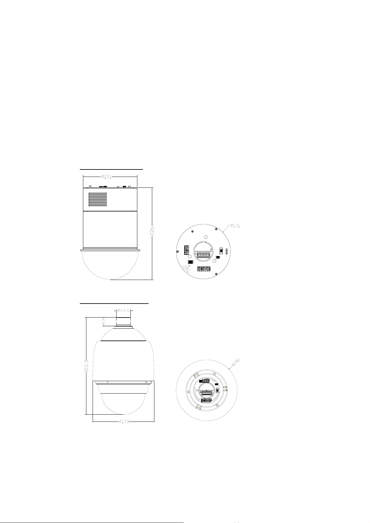
4.1 PTZ Camera Dimension
The indoor PTZ camera’s dimensions are Ø131 x 226 mm (5.2 x 8.9 Inches). The
outdoor camera’s dimensions are Ø172 x 302.5 mm (6.7x11.9 Inches) and Ø190 x
302.5 mm (7.5x11.9 Inches), with sunshield.
Indoor PTZ Camera
Installation Guide
Outdoor PTZ Camera
22
Page 24

Installation Guide
4.2 Optional Accessories
Indoor PTZ Camera Accessories
Transparent Cover/Smoke Cover (ZCA-CB-5.4/SB-5.4)
Diameter: 137 mm (5.4 inches)
5.4’’ Transparent Cover 5.4’’ Smoke Cover
Power Adapter
ZCA-100-1.5A Input: 100~115VAC/Output: 24VAC 36VA
ZCA-220-1.5A Input: 220~230VAC/Output: 24VAC 36VA
NOTE: When wiring, make sure the G/Y wire (Ground) inserted into the mid-pin
of the terminal block.
Outdoor PTZ Camera Accessories
Sunshield (ZCA-SSH) *equipped with Outdoor Camera
White, Height: 129.5 mm (5.05 inches); Diameter: 190 mm (7.48 inches); 0.15 kg (0.33
lbs)
Vandal Proof (Transparent)/PMMA(Transparent)/Smoke Cover
(ZCA-VP-XT/CB-XT/SB-XT) Diameter: 147 mm (5.8 inches)
Security Screw Set (for Vandal Proof Cover)
23
Page 25

Installation Guide
Power Adapter
ZCA-100-3.0A Input: 100~115VAC/Output: 24VAC 72VA
ZCA-220-3.0A Input: 220~230VAC/Output: 24VAC 72VA
NOTE: When wiring, make sure the G/Y wire (Ground) inserted into the mid-pin
of the terminal block.
Mounting Accessories
Hard Ceiling Mount (ZCA-HC200) / Indoor Camera
For Hard Ceiling use. Height: 21.4mm ; Diameter of the three holes: 4.5mm ; Diameter of
the bracket: 158mm
Indoor Mount Kit (ZCA-IPA) / Indoor Camera
For mounting indoor PTZ camera onto a pendent mount/Straight Tube.
White; Diameter: 140 mm (5.5 inches); Height: 74 mm (2.9 inches); 0.3 kg (0.7 lbs)
Attached Components: Waterproof Rubber, Hexagon Key, Lock Screw Plate, M5*8
screw×1, M5*8 security screw×1, M3*6 screw×1
24
Page 26

Installation Guide
T-Bar Ceiling Mount (ZCA-TB200) / Indoor Camera
For in-ceiling Installation use. Height: 170 mm (6.7 inches); Diameter: 180 mm (7.1
inches); 0.5 kg (1.1 lbs)
Ceiling Panel
For ceiling mounting. Zn platted; 610×305 mm (24×12 inches); Diameter: 135 mm (5.3
inches)
Standard Pendent Mount
White; 348×104×138.6 mm (13.7×4.1×5.5 inches); 1.5 kg (3.3 lbs); Diameter: 45 mm (1.8
inches). Supplied with rubber washer-8×1, pendent tube washer×1, spring washer-8×1
and M8*12 screw×1.
25
Page 27

Installation Guide
Mini Pendent Mount (ZCA-GT100) / Indoor/Outdoor
White; 184×104×115.2 mm (7.24×4.09×4.54 inches)
Supplied with rubber washer-8×1, pendent tube washer×1, spring washer-8×1 and M8*12
screw×1.
Straight Tube (ZCA-ST25,ST50) / Indoor/Outdoor
White; Iron; Height: 250/500 mm (9.8/19.7 inches); Diameter: 50 mm (2 inches)
1 kg (2.2 lbs) / 1.8 kg (4 lbs). Supplied with rubber washer-8×1, pendant tube washer×1,
spring waher-8×1 and waterproof rubber×1, M8*12 screw×1.
26
Mini Corner Plate (ZCA-MCP)
For mounting with Mini Pendent Mount.
270(L)×166(W)×95(D) mm (8.7×8×4.6 inches); Supplied with washer-8×4, spring
washer×4, M8*16 screw×4, M8 nut×4.
Page 28

Installation Guide
Pole Mount Adapter (ZCMA-PMA-H/ ZCMA-PMA-Q)
White; Height: 51mm (2 inches); Diameter: 52mm (2.04 inches); Thread size:1 1/2”
(ZCMA-PMA-H), 1 1/4” (ZCMA-PMA-Q)
ZCMA-PMA-H ZCMA-PMA-Q
Corner Standard Mounting Plate (ZCA-CST) / Indoor/Outdoor
White; 222(L)×204(W)×117(D) mm (8.7×8×4.6 inches); 2 kg (4.4 lbs). Supplied with
washer-8×4, spring washer×4, M8*20 screw×4, M8 nut×4.
Pole Thin Direct Mounting(ZCA-PTDM) / Indoor/Outdoor
White; 232(L)×136(W)×60(D) mm (9.1×5.4×2.4 inches); Diameter: 112~140 mm (4.4~5.5
inches); 0.7 kg (1.6 lbs). Supplied with stainless steel straps×4, M8*16 screw×4,
washer×4.
27
Page 29

Installation Guide
Pole Wide Direct Mounting (ZCA-PWDM) / Indoor/Outdoor
White; 270(L)×170(W)×60(D) mm (10.6×6.7×2.4 inches); Diameter: 112~130 mm (4.4~5
inches); 1 kg (2.2 lbs). Supplied with stainless steel straps×4, M8*16 screw×4, washer×4,
spring washer×4
Corner Thin Box (ZCA-CTB) ) / Indoor/Outdoor
White, 300(L)×164(W)×222(D) mm (11.8×6.5×8.7 inches); 3 kg (6.7 lbs); Supplied with
washer×4, M8*16 screw×4 and spring washer×4.
Corner Wide Box (ZCA-CWB) ) / Indoor/Outdoor
White; 232(L)×234(W)×210(D) mm (9.1×9.2×8.3 inches); 2.7 kg (6 lbs); Supplied with
washer×4, M8*16 screw×4 and spring washer×4.
28
Page 30

Installation Guide
Pole Thin Box (ZCA-PTB) ) / Indoor/Outdoor
White; 291(L)×170(W)×250(D) mm (11.5×5.3×9.5 inches); 3.1 kg (6.9 lbs); Supplied with
M8*16 screw×4, washer×4, spring washer×4, stainless steel straps×4.
Pole Wide Box (ZCA-PWB) ) / Indoor/Outdoor
White, 270(L)×166(W)×155(D) mm (10.6×6.5×6.1 inches); 3.2 kg (7.1 lbs); Supplied with
M8*16 screw×4, washer×4, spring washer×4, stainless steel straps×4.
Wall Box Mounting (ZCA-WBM) ) / Indoor/Outdoor
White, 270(L)×166(W)×95(D) mm (10.6×6.5×3.7 inches); 2.2 kg (4.84 lbs); Supplied with
M8*16 screw×4, washer×4, spring washer×4
29
Page 31

Stainless Steel Straps
For fixing Pole Direct Mounting/ Pole Box on the pole.
Width: 0.63”; 0.02 kg (0.04 lbs)
Stainless Strap Cutter
For tension, cut and crimp stainless steel straps. 1.4 kg (3.1 lbs)
Suitable for straps width: 1/2”, 5/8”, 3/4”
Other Application Accessories
Repeater/Converter
ZCA-RS422-485: RS-485/RS-232 Repeater
ZCA-RS232-485: RS-232 between RS-485/RS-422
ZCA-BP-485: Bi-phase to RS-485/RS-422
Installation Guide
ZCA-RS422-485 ZCA-RS232-485 ZCA-BP-485
Power Box
White, 186.5×147 mm (7.3×5.8 inches); 2.6 kg (5.8 lbs)
ZCA-PSU100
Input: 110~115VAC/Output: 24VAC 72VA
ZCA-PSU220
Input: 220~230VAC/Output: 24VAC 72VA
Connector Box (ZCA-CB) / Indoor
Recommended for wiring indoor dome alarm cables. White Color. 92×42 mm (3.7×1.7
inches); 0.13 kg (0.3 lbs); Supplied with cable×1, bracket×1 and M3*6 screw×2.
30
Page 32

Installation Guide
RS485 Distribution Unit (ZCA-DS4/8/16)
Relay control codes to speed dome cameras.
Dimension: 432×44×90 mm (17×17.32×35.43 inches)
4.3 Ceiling Mount
Generally, there are three kinds of ceiling mounting methods: hard-ceiling, in-ceiling
and mounting with straight tube. Refer to the following sections for more detailed
information.
The following figures show how cables connect to the camera in different ways.
Hard Ceiling Mount In-ceiling Mount
(cable exposed)
(cable recessed)
31
Page 33

4.3.1 Hard-Ceiling Mounting / Indoor
Hard Ceiling Mounting is a standard way of installation for Indoor PTZ Camera, and
general mounting accessories are equipped in the standard indoor PTZ Camera
package. Here lists the items and tools needed to mount the Camera onto the
ceilings. The supplied items are all in the PTZ Camera package.
Items Needed:
• PTZ Camera
• Hard Ceiling Mount and Decoration Ring (Supplied)
• Fixing Plate (Supplied)
Tools Needed:
• Tool for drilling
• (+,–) Screw Driver
Installation Guide
Follow the steps to install the camera for hard ceilings.
STEP 1
Screw the Fixing Plate to the PTZ
Camera, as shown in the figure.
STEP 2
Remove the Hard Ceiling Mount
from the Decoration Ring.
32
Page 34

Installation Guide
STEP 3
Attach the Mount to the ceiling.
Mark the locations where all three
ceiling holes should go.
STEP 4
Drill these holes on the hard
ceiling.
STEP 5
Fix the Mount to the holes on the
hard ceiling with three screws.
STEP 6
Thread the data cable through the
center hole of the Mount and
connect the cable to the PTZ
Camera.
STEP 7
Attach the PTZ Camera to the
Mount and rotate it clockwise.
Tighten the fixing screw to fix the
PTZ Camera.
33
Page 35

STEP 8
Fix the decoration ring to the
bracket.
NOTE: Make sure the
optical cover is removed
before carrying out the procedure.
Installation Guide
STEP 9
Place the optical cover back.
4.3.2 In-Ceiling Mounting / Indoor
Follow the steps to install the PTZ Camera with T-Bar Ceiling mount (ZCA-TB200)
accessory for In-Ceiling Mounting.
Here lists the items and tools needed to mount the PTZ Camera into the ceilings.
The supplied items are all in the standard PTZ Camera package.
Items Needed:
• PTZ Camera
• T-Bar (Optional Accessory)
• Supplied Screw (Equipped with T-Bar)
• Red Sticker (Equipped with T-Bar )
34
• Decoration Ring (Equipped with Hard Ceiling Mount as standard equipment)
Tools Needed:
• Tool for cutting a circle on the ceiling
• (+,–) Screw Driver
Step 1:
Disassemble the wing (indicated
in the diagram) from the T-Bar
Ceiling Mount, and take out the
supplied screw in the small bag.
Page 36

Installation Guide
Step 2:
Attach the separated wing to the
PTZ Camera, as shown in the
diagram.
STEP 3
Place the Red Sticker on the
ceiling plate, and cut the circle
part out of the ceiling.
STEP 4
Put up the T-Bar into the ceiling
opening.
STEP 5
Rotate T-Bar wings of the hinge to
fix the T-Bar at the edge of the
ceiling opening.
35
Page 37

STEP 6
Tighten the screws, and the T-Bar
wings will adhere to the ceiling.
STEP 7
Put the cable through the center
hole of the T-bar and connect it to
the PTZ Camera.
Installation Guide
STEP 8
Mount the PTZ Camera to the
Bracket and rotate it clockwise.
Tighten the fixing screw to fix the
Camera.
STEP 9
Fix the decoration ring to the
bracket and then place the optical
cover.
NOTE: Make sure the
optical cover is removed
before carrying out the
procedure.
36
Page 38

Installation Guide
4.3.3 In-Ceiling Mounting with Ceiling Panel
To mount the PTZ camera to a suspended ceiling with the T-Bar, the ceiling panel
could be employed, as shown in the figure below.
Follow the steps below for installing the ceiling panel.
Step 1: Cut the ceiling half.
Step 2: Put the ceiling panel upward to the ceiling opening.
Step 3: Attach and fasten the T-Bar mount onto the panel (Refer to 4.3.2 In-ceiling
Mounting for further details).
4.3.4 Ceiling Mounting with Straight Tube (ZCA-ST25/ST50)
The straight tube is available in different length: 25 cm and 30 cm. Procedures of
mounting the indoor and outdoor cameras with the straight tube will be described
respectively as follows.
Indoor PTZ Camera:
Items Needed
• PTZ Camera
• Data Cable (supplied)
• Straight Tube and other equipped items (optional accessory)
• Indoor Mount Kit and attached components (optional accessory)
• Screws and Screw Anchors for fixing the straight tube onto the ceiling (not
supplied)
Tools Needed
• Tool for drilling
• Tool for screwing
Follow the steps to mount the PTZ Camera with the Straight Tube.
1) Ensure that the ceiling can support the weight of the PTZ Camera and Straight
Tube.
2) Make a cable entry hole on the ceiling.
37
Page 39

Installation Guide
3) Fix the suspension bracket to the ceiling with proper screws and screw anchors
(not supplied).
4) Thread the cables through the Straight Tube and the Indoor Mount kit.
NOTE : After threading the cables, please block the cable entry hole with
the supplied sponge(s) to avoid insects entering the tube.
5) Fix the Indoor Mount Kit to the Straight Tube with the supplied screws and
washers.
6) Take out the Lock Screw Plate
from the small bag in the
Indoor Mount Kit’s package
and attach it to the PTZ
Camera’s back plate, as
shown in the picture.
7) Fix the plate onto the PTZ
Camera’s back plate with the
supplied small screw, as
marked in the figure.
8) Connect the cables to the PTZ Camera.
9) Mount the PTZ Camera to the
Indoor Mount Kit. (Ensure the
38
PTZ Camera is fixed
completely, and the thread
holes on the Lock Screw Plate
and Indoor Mount Kit are
aligned). Afterwards, screw
the supplied M5 standard
screw / security screw, as
shown in the picture.
Page 40

Installation Guide
Ceiling Mounting: Straight Tube + Indoor Mount Kit
Outdoor PTZ Camera:
Items Needed
• PTZ Camera
• Outdoor Mount Kit (supplied)
• Data Cable (supplied)
• Straight Tube and other equipped items (optional accessory)
• Waterproof Rubber (supplied)
• Screws and Screw Anchors for fixing the straight tube onto the ceiling (not
supplied)
Tools Needed
• Tool for drilling
• Tool for screwing
Follow the steps to mount the camera with the Straight Tube.
1) Ensure that the ceiling can support the weight of the PTZ Camera and Straight
Tube.
2) Make a cable entry hole on the ceiling.
3) Fix the Straight Tube to the ceiling with proper screws and screw anchors.
4) Attach the Waterproof Rubber to the Straight Tube.
5) Run the cable(s) through the Straight Tube with the Data Cable’s 22-pin cable
39
Page 41

Installation Guide
coming out of the outlet.
NOTE : After running the cable(s) through the Straight Tube, please block
the Tube’s outlet with the supplied sponge to avoid insects entering the
tube.
6) Thread the cable(s) through the Outdoor Mount Kit and join the Outdoor Mount
Kit to the Straight Tube with the supplied screws and washers. Then adjust the
Waterproof Rubber to the joint.
7) Connect the cable(s) to the PTZ Camera.
8) Join the PTZ Camera to the Outdoor Mount Kit with the supplied M5 screw and
washers.
Ceiling Mounting: Straight Tube + Outdoor Mount Kit
40
Page 42

Installation Guide
4.4 Wall Mount
The PTZ Camera can be mounted on the wall with Mini Pendent Mount, Standard
Pendent Mount and Wall Box. Please follow the installation instructions below for
mounting the PTZ Camera via different ways.
4.4.1 Mini Pendant Mount (ZCA-GT100)
Indoor PTZ Camera:
Items Needed
• PTZ Camera
• Data Cable (supplied)
• Mini Pendent Mount and equipped items (optional accessory)
• Indoor Mount Kit (optional accessory)
• Waterproof Rubber (Indoor Mount Kit’s accessory)
• Screws and Screw Anchors for fixing the Mini Pendant Mount (not supplied)
Tools Needed
• Tool for drilling
• Tool for screwing
Follow the steps below to mount the PTZ Camera with the Mini Pendent Mount.
1) Make a cable entry hole on the wall to recess the cables. Otherwise, users could
push up the Cable Entry Board on the Mini Pendent Mount’s Mounting Plate to
place the cables, as shown in the photo below.
Mounting Plate
Cable Entry Board
2) Fix the Mini Pendent Mount on the wall with proper screws and screw anchors.
3) Attach the Waterproof Rubber to the Mini Pendent Mount.
4) Run the cable(s) through the Mini Pendent Mount with the Data Cable’s 22-pin
cable coming out of the outlet.
NOTE: Please block the cable entry hole with the supplied sponge to
avoid insects entering the Pendant Mount. The sponge can be placed in
41
Page 43

Installation Guide
two ways as shown in the illustrations below.
Sponge
Sponge
5) Thread the cable(s) through the Indoor Mount Kit and join the Indoor Mount Kit to
the Mini Pendent Mount with the supplied screws and washers. Then adjust the
Waterproof Rubber to the joint.
6) Connect the cable(s) to the PTZ Camera.
7) Join the PTZ Camera to the Indoor Mount Kit with the supplied screw and
washers.
Wall Mounting: Mini Pendent Mount + Indoor Mount Kit
42
Page 44

Installation Guide
Outdoor PTZ Camera:
Items Needed
• PTZ Camera
• Outdoor Mount Kit (supplied)
• Data Cable (supplied)
• Mini Pendent Mount and equipped items (optional accessory)
• Waterproof Rubber (supplied)
• M5 Standard/Security Screw (supplied)
• Screws and Screw Anchors for fixing the Mini Pendent Mount (not supplied)
Tools Needed
• Tool for drilling
• Tool for screwing
Follow the steps below to mount the PTZ Camera with the Mini Pendent Mount.
1) Make a cable entry hole on the wall to recess the cables. Otherwise, users could
push up the Cable Entry Board on the Mini Pendent Mount’s Mounting Plate to
place the cables, as shown in the photo below.
Mounting Plate
Cable Entry Board
2) Fix the Mini Pendent Mount on the wall with proper screws and screw anchors.
3) Attach the Waterproof Rubber to the Mini Pendent Mount.
4) Run the cable(s) through the Mini Pendent Mount with the Data Cable’s 22-pin
cable coming out of the outlet.
NOTE: Please block the cable entry hole with the supplied sponge to
avoid insects entering the Pendent Mount. The sponge can be placed in
two ways as shown in the illustrations below.
43
Page 45

Installation Guide
Sponge
Sponge
5) Thread the cable(s) through the Outdoor Mount Kit and join the Outdoor Mount
Kit to the Mini Pendent Mount with the supplied screws and washers. Then adjust
the Waterproof Rubber to the joint.
6) Connect the cable(s) to the PTZ Camera.
7) Join the PTZ Camera to the Outdoor Mount Kit with the supplied M5 screw and
washers.
Wall Mounting: Mini Pendent Mount + Outdoor Mount Kit
44
Page 46

Installation Guide
4.4.2 Standard Pendent Mount
Indoor PTZ Camera:
Items Needed:
• PTZ Camera
• Data Cable (supplied)
• Standard Pendent Mount and equipped items (optional accessory)
• Indoor Mount Kit (optional accessory)
• Waterproof Rubber (Indoor Mount Kit’s accessory)
• Screws and Screw Anchors for fixing the Standard Pendent Mount onto the
ceiling (not supplied)
Tools Needed:
• Tool for drilling
• Tool for screwing
Follow the steps below to mount the PTZ Camera with the Standard Pendent Mount.
1) Make a cable entry hole on the wall to recess the cables. Otherwise, users could
push up the cable entry board on the Standard Pendent Mount’s mounting plate
to place the cables (see the illustration in section 4.4.1 Mini Pendent Mount
>
Step 1).
2) Fix the Standard Pendent Mount on the wall with proper screws and screw
anchors.
3) Attach the Waterproof Rubber to the Standard Pendent Mount.
4) Run the cable(s) through the Standard Pendent Mount with the Data Cable’s
22-pin cable coming out of the outlet.
NOTE: Please block the cable entry hole with the supplied sponge to
avoid insects entering the Pendent Mount. See the illustrations in section
4.4.1 Mini Pendent Mount
> Step 4.
5) Thread the cable(s) through the Indoor Mount Kit and join the Indoor Mount Kit to
the Standard Pendent Mount with the supplied screws and washers. Then adjust
the Waterproof Rubber to the joint.
6) Connect the cable(s) to the PTZ Camera.
7) Join the PTZ Camera to the Indoor Mount Kit with the supplied screw and
washers.
45
Page 47

Wall Mounting: Standard Pendent Mount + Indoor Mount Kit
Installation Guide
Outdoor PTZ Camera:
Items Needed
• PTZ Camera
• Outdoor Mount Kit (supplied)
• Data Cable (supplied)
• Standard Pendent Mount and equipped items (optional accessory)
• Waterproof Rubber (supplied)
• M5 Standard/Security Screw (supplied)
• Screws and Screw Anchors for fixing the Standard Pendent Mount onto the
ceiling (not supplied)
Tools Needed
• Tool for drilling
• Tool for screwing
Follow the steps below to mount the Dome Camera with the Standard Pendent
46
Mount.
1) Make a cable entry hole on the wall to recess the cables. Otherwise, users could
push up the cable entry board on the Standard Pendent Mount’s mounting plate
to place the cables (see the illustration in section 4.4.1 Mini Pendent Mount
>
Step 1).
2) Fix the Standard Pendent Mount on the wall with proper screws and screw
anchors.
Page 48

Installation Guide
3) Attach the Waterproof Rubber to the Standard Pendent Mount.
4) Run the cable(s) through the Standard Pendent Mount with the Data Cable’s
22-pin cable coming out of the outlet.
NOTE: Please block the cable entry hole with the supplied sponge to
avoid insects entering the Pendent Mount. See the illustrations in section
4.4.1 Mini Pendent Mount
> Step 4.
5) Thread the cable(s) through the Outdoor Mount Kit and join the Outdoor Mount
Kit to the Standard Pendent Mount with the supplied screws and washers. Then
adjust the Waterproof Rubber to the joint.
6) Connect the cable(s) to the PTZ Camera.
7) Join the PTZ Camera to the Outdoor Mount Kit with the supplied M5 screw and
washers.
Wall Mounting: Standard Pendent Mount + Outdoor Mount Kit
47
Page 49

4.4.3 Wall Box Mounting (ZCA-WBM)
Indoor PTZ Camera:
Items Needed
• PTZ Camera
• Data Cable (supplied)
• Standard/Mini Pendent Mount and equipped items (optional accessory)
• Wall Box Mounting (optional accessory)
• Indoor Mount Kit (optional accessory)
• Waterproof Rubber (Indoor Mount Kit’s accessory)
• Screws and Screw Anchors for fixing the Wall Box Mounting onto the ceiling
(not supplied)
Tools Needed
• Tool for drilling
Installation Guide
• Tool for screwing
Follow the steps to mount the Dome Camera with the Standard/Mini Pendent Mount
and Wall Box Mounting.
1) Make a cable entry hole on the wall to recess the cable(s).
2) Fix the Wall Box Mounting on the wall with proper screws and screw anchors.
Then run the cable(s) through the hole on the Wall Box Mounting with the Data
Cable’s 22-pin cable coming out.
3) Fasten the Standard/Mini Pendent Mount onto the Wall Box Mounting with the
supplied screws and washers. Then thread the cable(s) through the
Standard/Mini Pendent Mount with the cable(s) coming out of the Pendent
Mount’s outlet.
NOTE: Please block the cable entry hole with the supplied sponge to
48
avoid insects entering the Pendent Mount. See the illustrations in section
4.4.1 Mini Pendent Mount
> Step 4.
4) Attach the Waterproof Rubber to the Standard/Mini Pendent Mount.
5) Thread the cable(s) through the Indoor Mount Kit and join the Indoor Mount Kit to
the Standard/Mini Pendent Mount with the supplied screws and washers. Then
adjust the Waterproof Rubber to the joint.
6) Connect the cable(s) to the PTZ Camera.
7) Join the PTZ Camera to the Indoor Mount Kit with the supplied screw and
Page 50

Installation Guide
washers.
Wall Box Mounting: Wall Box Mounting + Standard/Mini Pendent Mount + Indoor
Mount Kit
Outdoor PTZ Camera:
Items Needed
• PTZ Camera
• Outdoor Mount Kit (supplied)
• Data Cable (supplied)
• Standard/Mini Pendent Mount and equipped items (optional accessory)
• Wall Box Mounting (optional accessory)
• Waterproof Rubber (supplied)
• M5 Standard/Security Screw (supplied)
• Screws and Screw Anchors for fixing the Wall Box Mounting onto the ceiling
(not supplied)
Tools Needed
• Tool for drilling
• Tool for screwing
Follow the steps to mount the PTZ Camera with the Standard/Mini Pendent Mount
and Wall Box Mounting.
1) Make a cable entry hole on the wall to recess the cable(s).
2) Fix the Wall Box Mounting on the wall with proper screws and screw anchors.
49
Page 51

Installation Guide
Then run the cable(s) through the hole on the Wall Box Mounting with the Data
Cable’s 22-pin cable coming out.
3) Fasten the Standard/Mini Pendent Mount onto the Wall Box Mounting with the
supplied screws and washers. Then thread the cable(s) through the
Standard/Mini Pendent Mount with the cable(s) coming out of the Pendent
Mount’s outlet.
NOTE: Please block the cable entry hole with the supplied sponge to
avoid insects entering the Pendent Mount. See the illustrations in section
4.4.1 Mini Pendent Mount
> Step 4.
4) Attach the Waterproof Rubber to the Standard/Mini Pendent Mount.
5) Thread the cable(s) through the Outdoor Mount Kit and join the Outdoor Mount
Kit to the Standard/Mini Pendent Mount with the supplied screws and washers.
Then adjust the Waterproof Rubber to the joint.
6) Connect the cable(s) to the PTZ Camera.
7) Join the PTZ Camera to the Outdoor Mount Kit with the supplied screw and
washers.
Wall Box Mounting: Wall Box Mounting + Standard/Mini Pendent Mount + Outdoor
Mount Kit
50
Page 52

Installation Guide
4.5 Corner Mount
4.5.1 Standard/Mini Corner Mounting Plate (ZCA-CST/MCP)
Indoor PTZ Camera:
Items Needed
• PTZ Camera
• Data Cable (supplied)
• Standard/Mini Pendent Mount and equipped items (optional accessory)
• Standard/Mini Corner Mounting Plate (herein collectively called “Corner
Mounting Plate”; optional accessory)
• Indoor Mount Kit (optional accessory)
• Waterproof Rubber (Indoor Mount Kit’s accessory)
• Screws and Screw Anchors for fixing the Corner Mounting Plate (not
supplied)
Tools Needed
• Tool for drilling
• Tool for screwing
Follow the steps below to mount the PTZ Camera with the Corner Mounting Plate
and Standard/Mini Pendent Mount.
1) Make a cable entry hole on the wall to recess the cable(s).
2) Fix the Corner Mounting Plate on the corner of the wall with proper screws and
screw anchors. Then run the cable(s) through the hole on the Corner Mounting
Plate with the Data Cable’s 22-pin cable coming out.
3) Fasten the Standard/Mini Pendent Mount onto the Corner Mounting Plate with
the supplied screws and washers. Then thread the cable(s) through the
Standard/Mini Pendent Mount with the cable(s) coming out of the Pendent
Mount’s outlet.
NOTE: Please block the cable entry hole with the supplied sponge to
avoid insects entering the Pendent Mount. See the illustrations in section
4.4.1 Compact Pendent Mount
> Step 4.
4) Attach the Waterproof Rubber to the Standard/Mini Pendent Mount.
5) Thread the cable(s) through the Indoor Mount Kit and join the Indoor Mount Kit to
the Standard/Mini Pendent Mount with the supplied screws and washers. Then
adjust the Waterproof Rubber to the joint.
6) Connect the cable(s) to the PTZ Camera.
7) Join the PTZ Camera to the Indoor Mount Kit with the supplied screw and
51
Page 53

Installation Guide
washers.
Corner Wall Mounting: Corner Standard/Mini Mounting Plate + Standard/Mini
Pendent Mount + Indoor Mount Kit
Outdoor PTZ Camera:
Items Needed
• PTZ Camera
• Outdoor Mount Kit (supplied)
• Data Cable (supplied)
• Standard/Mini Pendent Mount and equipped items (optional accessory)
• Standard/Mini Corner Mounting Plate (herein collectively called “Corner
Mounting Plate”; optional accessory)
• Waterproof Rubber (supplied)
• M5 Standard/Security Screw (supplied)
• Screws and Screw Anchors for fixing the Corner Mounting Plate (not
supplied)
Tools Needed
52
• Tool for drilling
• Tool for screwing
Follow the steps below to mount the PTZ Camera with the Corner Mounting Plate
and Standard/Compact Pendent Mount.
1) Make a cable entry hole on the wall to recess the cable(s).
Page 54

Installation Guide
2) Fix the Corner Mounting Plate on the corner of the wall with proper screws and
screw anchors. Then run the cable(s) through the hole on the Corner Mounting
Plate with the Data Cable’s 22-pin cable coming out.
3) Fasten the Standard/Mini Pendent Mount onto the Corner Mounting Plate with
the supplied screws and washers. Then thread the cable(s) through the
Standard/Mini Pendent Mount with the cable(s) coming out of the Pendent
Mount’s outlet.
NOTE: Please block the cable entry hole with the supplied sponge to
avoid insects entering the Pendent Mount. See the illustrations in section
4.4.1 Compact Pendent Mount
> Step 4.
4) Attach the Waterproof Rubber to the Standard/Mini Pendent Mount.
5) Thread the cable(s) through the Outdoor Mount Kit and join the Outdoor Mount
Kit to the Standard/Mini Pendent Mount with the supplied screws and washers.
Then adjust the Waterproof Rubber to the joint.
6) Connect the cable(s) to the PTZ Camera.
7) Join the PTZ Camera to the Outdoor Mount Kit with the supplied M5 screw and
washers.
Corner Wall Mounting: Corner Standard/Mini Mounting Plate + Standard/Compact
Pendent Mount + Outdoor Mount Kit
53
Page 55

4.5.2 Corner Thin/Wide Box Mounting (ZCA-CTB/CWB)
Indoor PTZ Camera:
Items Needed
• PTZ Camera
• Data Cable (supplied)
• Standard/Mini Pendent Mount and equipped items (optional accessory)
• Corner Thin/Wide Box (optional accessory)
• Indoor Mount Kit (optional accessory)
• Waterproof Rubber (Indoor Mount Kit’s accessory)
• Screws and Screw Anchors for fixing the Corner Thin/Wide Box (not
supplied)
Tools Needed
• Tool for drilling
Installation Guide
• Tool for screwing
Follow the steps below to mount the PTZ Camera with the Corner Thin/Wide Box
and Standard/Mini Pendent Mount.
1) Make a cable entry hole on the wall to recess the cable(s).
2) Fix the Corner Thin/Wide Box on the corner of the wall with proper screws and
screw anchors. Then run the cable(s) through the hole on the Corner Mounting
Plate with the Data Cable’s 22-pin cable coming out.
3) Fasten the Standard/Mini Pendent Mount onto the Corner Thin/Wide Box with the
supplied screws and washers. Then thread the cable(s) through the
Standard/Mini Pendent Mount with the cable(s) coming out of the Pendent
Mount’s outlet.
NOTE: Please block the cable entry hole with the supplied sponge to
avoid insects entering the Pendent Mount. See the illustrations in section
54
4.4.1 Compact Pendent Mount
> Step 4.
4) Attach the Waterproof Rubber to the Standard/Mini Pendent Mount.
5) Thread the cable(s) through the Indoor Mount Kit and join the Indoor Mount Kit to
the Standard/Mini Pendent Mount with the supplied screws and washers. Then
adjust the Waterproof Rubber to the joint.
6) Connect the cable(s) to the PTZ Camera.
7) Join the PTZ Camera to the Indoor Mount Kit with the supplied screw and
washers.
Page 56

Installation Guide
Corner Box Mounting: Corner Thin/Wide Box + Standard/Mini Pendent Mount +
Indoor Mount Kit
Outdoor PTZ Camera:
Items Needed
• PTZ Camera
• Outdoor Mount Kit (supplied)
• Data Cable (supplied)
• Standard/Compact Pendent Mount and equipped items (optional accessory)
• Corner Thin/Wide Box (optional accessory)
• Waterproof Rubber (supplied)
• M5 Standard/Security Screw (supplied)
• Screws and Screw Anchors for fixing the Corner Thin/Wide Box (not
supplied)
Tools Needed
• Tool for drilling
• Tool for screwing
Follow the steps below to mount the PTZ Camera with the Corner Thin/Wide Box
and Standard/Mini Pendent Mount.
1) Make a cable entry hole on the wall to recess the cable(s).
2) Fix the Corner Thin/Wide Box on the corner of the wall with proper screws and
screw anchors. Then run the cable(s) through the hole on the Corner Mounting
Plate with the Data Cable’s 22-pin cable coming out.
55
Page 57

Installation Guide
3) Fasten the Standard/Mini Pendent Mount onto the Corner Thin/Wide Box with the
supplied screws and washers. Then thread the cable(s) through the
Standard/Mini Pendent Mount with the cable(s) coming out of the Pendent
Mount’s outlet.
NOTE: Please block the cable entry hole with the supplied sponge to
avoid insects entering the Pendent Mount. See the illustrations in section
4.4.1 Compact Pendent Mount
> Step 4.
4) Attach the Waterproof Rubber to the Standard/Mini Pendent Mount.
5) Thread the cable(s) through the Outdoor Mount Kit and join the Outdoor Mount
Kit to the Standard/Mini Pendent Mount with the supplied screws and washers.
Then adjust the Waterproof Rubber to the joint.
6) Connect the cable(s) to the PTZ Camera.
7) Join the PTZ Camera to the Outdoor Mount Kit with the supplied M5 screw and
washers.
Corner Box Mounting: Corner Thin/Wide Box + Standard/Mini Pendent Mount +
Outdoor Mount Kit
56
Page 58

Installation Guide
4.6 Pole Mount
4.6.1 Pole Thin/Wide Direct Mounting (ZCA-PTDM/PWDM)
Indoor PTZ Camera:
Items Needed
• PTZ Camera
• Data Cable (supplied)
• Standard/Mini Pendent Mount and equipped items (optional accessory)
• Pole Thin/Wide Direct Mounting (optional accessory)
• Indoor Mount Kit (optional accessory)
• Waterproof Rubber (Indoor Mount Kit’s accessory)
• Stainless Steel Straps for fixing the Pole Thin/Wide Direct Mounting
(optional accessory)
Tools Needed
• Stainless Strap Cutter
• Tool for screwing
Follow the steps below to mount the PTZ Camera with the Pole Thin/Wide Direct
Mounting and Standard/Mini Pendent Mount.
1) Fasten the Pole Thin/Wide Direct Mounting on a pole with equipped stainless
straps.
2) Run the cable(s) through the hole on the Pole Thin/Wide Direct Mounting with the
Data Cable’s 22-pin cable coming out.
3) Fasten the Standard/Mini Pendent Mount onto the Pole Thin/Wide Direct
Mounting with the supplied screws and washers. Then thread the cable(s)
through the Standard/Mini Pendent Mount with the cable(s) coming out of the
Pendent Mount’s outlet.
NOTE: Please block the cable entry hole with the supplied sponge to
avoid insects entering the Pendent Mount. See the illustrations in section
4.4.1 Compact Pendent Mount
> Step 4.
4) Attach the Waterproof Rubber to the Standard/Mini Pendent Mount.
5) Thread the cable(s) through the Indoor Mount Kit and join the Indoor Mount Kit to
the Standard/Mini Pendent Mount with the supplied screws and washers. Then
adjust the Waterproof Rubber to the joint.
6) Connect the cable(s) to the PTZ Camera.
7) Join the PTZ Camera to the Indoor Mount Kit with the supplied screw and
washers.
57
Page 59

Installation Guide
Pole Direct Mounting: Pole Thin/Wide Direct Mounting + Standard/Mini Pendent
Mount + Indoor Mount Kit
Outdoor PTZ Camera:
Items Needed
• PTZ Camera
• Outdoor Mount Kit (supplied)
• Data Cable (supplied)
• Standard/Mini Pendent Mount and equipped items (optional accessory)
• Pole Thin/Wide Direct Mounting (optional accessory)
• Waterproof Rubber (supplied)
• M5 Standard/Security Screw (supplied)
• Stainless Steel Straps for fixing the Pole Thin/Wide Direct Mounting
(optional accessory)
Tools Needed
• Stainless Strap Cutter
• Tool for screwing
Follow the steps below to mount the PTZ Camera with the Pole Thin/Wide Direct
58
Mounting and Standard/Mini Pendent Mount.
1) Fasten the Pole Thin/Wide Direct Mounting on a pole with equipped stainless
straps.
2) Run the cable(s) through the hole on the Pole Thin/Wide Direct Mounting with the
Data Cable’s 22-pin cable coming out.
3) Fasten the Standard/Mini Pendent Mount onto the Pole Thin/Wide Direct
Mounting with the supplied screws and washers. Then thread the cable(s)
Page 60

Installation Guide
through the Standard/Mini Pendent Mount with the cable(s) coming out of the
Pendent Mount’s outlet.
NOTE: Please block the cable entry hole with the supplied sponge to
avoid insects entering the Pendent Mount. See the illustrations in section
4.4.1 Compact Pendent Mount
> Step 4.
4) Attach the Waterproof Rubber to the Standard/Mini Pendent Mount.
5) Thread the cable(s) through the Outdoor Mount Kit and join the Outdoor Mount
Kit to the Standard/Mini Pendent Mount with the supplied screws and washers.
Then adjust the Waterproof Rubber to the joint.
6) Connect the cable(s) to the PTZ Camera.
7) Join the PTZ Camera to the Outdoor Mount Kit with the supplied M5 screw and
washers.
Pole Direct Mounting: Pole Thin/Wide Direct Mounting + Standard/Mini Pendent
Mount + Outdoor Mount Kit
59
Page 61

4.6.2 Pole Thin/Wide Box Mounting (ZCA-PTB/PWB)
Indoor PTZ Camera:
Items Needed
• PTZ Camera
• Data Cable (supplied)
• Standard/Mini Pendent Mount and equipped items (optional accessory)
• Pole Thin/Wide Box Mounting (optional accessory)
• Indoor Mount Kit (optional accessory)
• Waterproof Rubber (Indoor Mount Kit’s accessory)
• Stainless Steel Straps for fixing the Pole Thin/Wide Box Mounting (optional
accessory)
Tools Needed
• Stainless Strap Cutter
Installation Guide
• Tool for screwing
Follow the steps below to mount the PTZ Camera with the Pole Thin/Wide Box and
Standard/Mini Pendent Mount.
1) Fasten the Pole Thin/Wide Box on a pole with equipped stainless straps.
2) Run the cable(s) through the hole on the Pole Thin/Wide Box Mounting with the
Data Cable’s 22-pin cable coming out.
3) Fasten the Standard/Mini Pendent Mount onto the Pole Thin/Wide Box Mounting
with the supplied screws and washers. Then thread the cable(s) through the
Standard/Mini Pendent Mount with the cable(s) coming out of the Pendent
Mount’s outlet.
NOTE: Please block the cable entry hole with the supplied sponge to
avoid insects entering the Pendent Mount. See the illustrations in section
4.4.1 Compact Pendent Mount
> Step 4.
60
4) Attach the Waterproof Rubber to the Standard/Mini Pendent Mount.
5) Thread the cable(s) through the Indoor Mount Kit and join the Indoor Mount Kit to
the Standard/Mini Pendent Mount with the supplied screws and washers. Then
adjust the Waterproof Rubber to the joint.
6) Connect the cable(s) to the PTZ Camera.
7) Join the PTZ Camera to the Indoor Mount Kit with the supplied screw and
washers.
Page 62

Installation Guide
Pole Box Mounting: Pole Thin/Wide Box + Standard/Mini Pendent Mount + Indoor
Mount Kit
Outdoor PTZ Camera:
Items Needed:
• PTZ Camera
• Outdoor Mount Kit (supplied)
• Data Cable (supplied)
• Standard/Mini Pendent Mount and equipped items (optional accessory)
• Pole Thin/Wide Box Mounting (optional accessory)
• Waterproof Rubber (supplied)
• M5 Standard/Security Screw (supplied)
• Stainless Steel Straps for fixing the Pole Thin/Wide Box Mounting (optional
accessory)
Tools Needed:
• Stainless Strap Cutter
• Tool for screwing
Follow the steps below to mount the PTZ Camera with the Pole Thin/Wide Box and
Standard/Mini Pendent Mount.
1) Fasten the Pole Thin/Wide Box on a pole with equipped stainless straps.
2) Run the cable(s) through the hole on the Pole Thin/Wide Box Mounting with the
Data Cable’s 22-pin cable coming out.
3) Fasten the Standard/Mini Pendent Mount onto the Pole Thin/Wide Box Mounting
with the supplied screws and washers. Then thread the cable(s) through the
61
Page 63

Installation Guide
Standard/Mini Pendent Mount with the cable(s) coming out of the Pendent
Mount’s outlet.
NOTE: Please block the cable entry hole with the supplied sponge to
avoid insects entering the Pendent Mount. See the illustrations in section
4.4.1 Compact Pendent Mount
> Step 4.
4) Attach the Waterproof Rubber to the Standard/Mini Pendent Mount.
5) Thread the cable(s) through the Outdoor Mount Kit and join the Outdoor Mount
Kit to the Standard/Mini Pendent Mount with the supplied screws and washers.
Then adjust the Waterproof Rubber to the joint.
6) Connect the cable(s) to the PTZ Camera.
7) Join the PTZ Camera to the Outdoor Mount Kit with the supplied M5 screw and
washers.
Pole Box Mounting: Pole Thin/Wide Box + Standard/Mini Pendent Mount + Outdoor
Mount Kit
62
Page 64

Installation Guide
5. System Expansion
5.1 Connecting with Connector Box (Indoor Use)
Ideally being used in indoor installation circumstances, a Connector Box provides
easy wiring and well organized connection between alarms, cameras and other
devices, for easy installation.
To connect the connector box with other devices:
• Use a RS 485 cable (CAT 5 is recommended) to complete RS 485
communication wiring with control devices such as DVRs and Control
Keyboards.
• Use a 22-pin cable to connect the connector box to the camera.
For more detailed information, please refer to the connector box user’s manual.
A system wired with a connector box is illustrated in the following diagram.
63
Page 65

5.2 Connecting with Power Box
A power box contains a 24V AC adapter, two terminal blocks (for communication
and power) and one alarm board. With an IP66 case, the Power Box is ideal for
outdoor installation environment. Two models are available: 100~115V AC power
input (P1030) and 220~230V AC (P2030). Additionally, users can either connect one
camera to one power box and to Internet or to other control devices (DVR, Control
Keyboard and monitors), as shown in the diagrams below. For more detailed
information, please refer to the power box user’s manual.
Installation Guide
Connecting the Camera to the Power Box and Internet
Connecting the Camera to the Power Box and Various Control Devices
64
Page 66

Installation Guide
5.3 Repeater Application
To integrate other surveillance devices with the cameras or to extend the distance of
communications, users could employ three kinds of repeater/converter, as shown
below. With the advanced circuit design, these repeaters/converters offer 1KVrms
isolation voltage and surge protection capability. The exiting network can be
protected by the repeaters/converters. Up to 10 devices are allowed to connect to
one repeater/converter. For detailed information, please refer to the
repeater/converter user’s manual.
ZCA-RS422-485
RS-485/RS-422 Repeater
ZCA-RS232-485
RS-232 between
RS-485/RS-422
ZCA-BP-485
Bi-Phase to
RS-485/RS-422
ZCA-RS422-485: Extend the distance of RS-485 or RS-422 communications
ZCA-RS232-485: Either Bridge RS-232 equipments to a RS-485 or RS-422
network or bridge RS-485/RS-422 equipments to a RS-232
network
ZCA-BP-485 : Bridge Bi-Phase equipments to a RS-485 or RS-422 network
65
Page 67

5.4 RS485 Distribution Unit (ZCA-DS4/8/16)
The RS-485 Distribution Unit (SDU) is designed to relay control codes to cameras. It
is capable of communicating with cameras up to 1 kilometer away. Additionally, the
SDU can be installed in either “star” or “daisy chain” configuration with up to 160
cameras (see the diagrams below). Its versatile installation configuration makes an
easy integration into expanding surveillance systems. For more information, please
refer to the SDU user’s manual.
Installation Guide
Star Configuration
Daisy Chain Configuration
66
Page 68

Installation Guide
6. System Integration
The PTZ Camera is allowed to be integrated into other suppliers' surveillance
systems with large set of built-in protocols. Refer to the following sections for more
information.
6.1 Using Pelco Keyboard
The PTZ Camera can be controlled through the Pelco keyboard. Please follow the
instructions below to manipulate the camera.
Open the OSD
<9 5> + hold <Preset>
<7 7> + <Preset>
ENTER
Iris Open
<9 5> + hold <Preset>
Press the keys, <9 5> + hold <Preset> or <7 7> +
<Preset>, to display the OSD menu.
To send a “ENTER” command, press <Iris Open> or <9
5> + hold <Preset>.
Set and execute PRESET
Hold <Preset>
<Preset> To execute a preset position, press the key <Preset>.
Set and execute SEQUENCE
By OSD
<7 0~7 8> + <Preset>
To set “Preset”, hold the key <Preset>.
To set “Sequence”, please enter the OSD and go to the
Preset setting menu.
The following Presets allows you to execute Sequence
quickly.
***<7 0> + <Preset>: Sequence 1
<7 1> + <Preset>: Sequence 2
.
.
.
<7 6> + <Preset>: Sequence 7
<7 8> + <Preset>: Sequence 8
***<7 7> + <Preset>: Reserved; also used to Open
OSD
Set and execute CRUISE
Hold <Pattern>
<Preset> To execute “Cruise,” press the key <Pattern>.
To set “Cruise”, hold the key <Pattern>.
67
Page 69

Set Auto Pan
Installation Guide
By OSD
To set “Auto Pan”, please enter the OSD and go to the
Auto Pan setting menu.
The following Presets allows you to execute Auto Pan
quickly.
***<7 9> + <Preset>: Auto Pan 1
<7 9 ~ 8 2><Preset>
<8 0> + <Preset>: Auto Pan 2
<8 1> + <Preset>: Auto Pan 3
<8 2> + <Preset>: Auto Pan 4
Cable Length
RS-485 is the interface that communicates the PTZ camera and its control device.
The recommended cables for RS-485 communication are CAT 5 cables; maximum
cable length for over 24-gauge wire is 4000 feet (1219 meters). If the total cable
length exceeds 4000 feet, using a repeater to enlare the signals is recommended.
Cable Definition (P Protocol Keyboard to the PTZ Camera)
Tx+
8
Tx-
7
6
5
+12V
4
GND
Rx-
2
Rx+
1
For P Protocol Keyboard
For Spee dDome
Cable Definition (D Protocol Keyboard to the PTZ Camera)
6
Tx Tx+
5
4
GND
3
GND
2
Rx-
1
Rx+
For SpeedDomeFor D Protocol Keyboard
2
3
4
5
6
1
Tx+
+12V
GND
Rx+
RxTx-
1
2
3
4
5
6
Tx+
GND
Rx+
RxTx-
68
Page 70

Installation Guide
6.2 Using Phillips Allegiant Keyboard
The PTZ Camera can be integrated into Philips Allegiant systems through D77R3
repeaters. Please follow the instructions to control the cmera through Philips
Allegiant systems.
Symbol Definition
<shot> Command dome cameras to go to specific preset position.
<set> Set preset position.
Open the OSD
<ON> + <4 6> + <Enter>
<7 7> + <shot>
ENTER
Iris
<7 7> + <shot>
Press the keys, <ON> + <4 6> + <Enter> or <7 7> +
<shot>, to display the OSD menu.
To send a “ENTER” command, press <Iris
Open/Close> or <7 7> + <shot>.
Set and execute PRESET
<set>
To set “Preset”, use the key <set>.
<shot> To execute a preset position, use the key <shot>.
Set and execute SEQUENCE
By OSD
To set “Sequence”, please enter the OSD and go to the
Preset setting menu.
The following Presets allows you to execute Sequence
quickly.
***<7 0> + <shot>: Sequence 1
<7 1> + <shot>: Sequence 2
.
<7 0~7 8> + <shot>
.
.
<7 6> + <shot>: Sequence 7
<7 8> + <shot>: Sequence 8
***<7 7> + <shot>: Reserved; also used to Open
OSD
69
Page 71

Set and execute CRUISE
Installation Guide
<ON> + <5 0> + <Enter>
To start recording “Cruise”, press the keys <ON> + <5
0> + <Enter>.
<OFF> + <5 0> + <Enter>
To end recording “Cruise”, press the keys <ON> + <5
0> + <Enter>.
<Preset> To execute “Cruise,” press the key <Pattern>.
Set and execute Auto Pan
By OSD
To set “Auto Pan”, please enter the OSD and go to the
Auto Pan setting menu.
The following Presets allows you to execute Auto Pan
quickly.
***<7 9> + <shot>: Auto Pan 1
<7 9 ~ 8 2><shot>
<8 0> + <shot>: Auto Pan 2
<8 1> + <shot>: Auto Pan 3
<8 2> + <shot>: Auto Pan 4
Control Dome Camera Using Allegiant Keyboard
• User can move the cursor left/right/up/down through pushing joystick
left /right/up/down.
• Some differences for ENTER command.
User cannot send ENTER command directly. User can send a ENTER command
through “ 7 7 <Set> “.
70
Page 72

Installation Guide
Appendix A: Technical Specification
Items 18× Model 26× Model 35× Model
CAMERA
CCD Sensor
Progressive Scan
Optical Zoom
Digital Zoom
Effective Pixels
Horizontal Resolution
Scanning System
Synchronization
Video Output
S/N Ratio
Minimum Illumination
Focal Length
Focus Mode
White Balance
Iris Control
Electronic
Shutter
NTSC
PAL
NTSC
PAL
1/4" EXview 1/4" EXview 1/4" CCD
- - Yes
18× 26× 35x
1× ~ 12× variable
380k
440k
530 TVL 530 TVL 540 TVL
NTSC / PAL
Internal / Line Lock
1.0 Vp-p / 75 Ω, BNC
> 50 dB (AGC Off)
0.07 lux; 0.01 lux (B/W) 0.09 lux; 0.01 lux (B/W) 0.1 lux; 0.01 lux (B/W)
4.1~73.8 mm 3.5~91 mm 3.4~119 mm
Auto / Manual
Auto / Manual
Auto / Manual
1/1~1/10k sec. 1/1~1/10k sec. 1/1~1/30k sec.
1/1~1/10k sec. 1/1~1/10k sec. 1/1~1/30k sec.
AGC control
Back Light Compensation
OPERATION
Built-in Protocol
Multi-Language OSD
Pan Travel
Tilt Travel
Manual Speed
Presets
Preset Accuracy
Preset Speed
Sequence
Auto Pan
Cruise
Privacy Mask
Proportional Pan & Tilt
Auto / Manual
On / Off
Ganz-PT, Pelco D&P, VCL, Philips, AD-422, JVC, Kalatel, etc.
English, French, German, Italian, Japanese, Polish, Portuguese,
Russian, Spanish, Turkish, Simplified Chinese, Traditional Chinese
360° endless
-10° ~ 190°
0.5° ~ 90°/s
256
0.225°
5° ~ 400°/s
8
4
8
24 24 8
On / Off (Pan and tilt speed proportional to zoom ratio)
Resume after Power loss
Zone Title
Home Function
Yes
16
Preset, Sequence, Auto pan, Cruise
71
Page 73

Installation Guide
Items 18× Model 26× Model 35× Model
Auto Flip
Digital Slow Shutter
Electronic Image Stabilizer
Motion Detection
Wide Dynamic Range
Day/Night: IR Cut Filter
Image Inverse
Image Freeze
Digital Noise Reduction
Alarm Input
Alarm Output
Alarm Reaction
GENERAL
Environment
Controller Interface
Operating
Temperature
Waterproof Standard
Indoor
Outdoor
Digital / Mechanical / Off
On / Off On / Off On / Off
- - On / Off
On / Off On / Off On / Off
On / Off On / Off On / Off
On / Off On / Off On / Off
On / Off On / Off On / Off
On / Off On / Off On / Off
- - On / Off
8
1
Preset, Sequence, Auto pan, Cruise
Indoor / Outdoor
RS-485
0°C ~ 40°C (32°F ~ 104°F)
-50°C ~ 50°C (-58°F ~ 122°F)
IP66 standard
Dimension
Weight
Power Source
Power
Consumption
Regulatory
Networking
Video Compression
Video Streaming
Video Size
Frame Rate
Audio Compression
Audio Streaming
Interface
Indoor
Outdoor
Indoor
Outdoor
Indoor
Outdoor
Ø131 x 226 mm (5.2 x 8.9 Inches)
Ø 172 x 302.5 mm (6.7 x 11.9 Inches) /
Ø 190 x 302.5 mm ( 7.5x 11.9 Inches), with sunshield
1.6 kg (3.5 lbs)
2.6 kg (5.7 lbs)
AC 24V ± 10%
20 W
65 W (with Heater)
CE, FCC, RoHS
H.264 Main Profile, MJPEG
Dual H.264 / Simultaneously H.264 + MJPEG
D1: NTSC 720x480 / PAL 720x576
CIF: NTSC 352x240 / 352x288
30 fps @ D1 Resolution
G.726 ADPCM / AAC
Full-duplex, Half-duplex, Simplex
RJ45, 10/100 Mbps Ethernet
Protocols
Alarm
Alarm Reaction
Security
Supported Web Browser
72
TCP/IP, UDP, HTTP, FTP, SMTP, ARP, ICMP, DHCP, RTP/RTSP
4 digital alarm inputs / 1 alarm output
Preset, Sequence, Auto-Pan, Cruise
User Account and Password Protection
Windows – Microsoft Internet Explorer 6.x or later
Page 74

Installation Guide
Items
CAMERA
CCD Sensor Sony CCD
Optical Zoom 18× 30× 36×
Digital Zoom 1~12x variable
Effective Pixels NTSC 480k 480k 480k
NEW
18× Model
NEW
30× Model
NEW
36× Model
PAL
Horizontal Resolution 650 TVL 650 TVL 650 TVL
Scanning System NTSC / PAL
Synchronization
Video Output 1.0 Vp-p / 75 Ω, BNC
S/N Ratio > 50 dB (AGC Off)
Minimum Illumination
Focal Length 3.4~61.2 mm 3.4~102 mm 3.4~122.4 mm
Focus Mode Auto / Manual
White Balance Auto / Manual
Iris Control Auto / Manual
Electronic Shutter
AGC control Auto / Manual
Back Light Compensation On/Off
OPERATION
570k 570k 570k
Internal / Line Lock
0.1 lux
0.01lux(B/W)
0.1 lux
0.01lux(B/W)
1/1~1/10k sec.
0.1 lux
0.01lux(B/W)
Built-in Protocol
Multi-Language OSD English, French, German, Italian, Japanese, Polish, Portuguese,
Pan Travel 360° endless
Tilt Travel -10° ~ 190°
Manual Speed 0.5°~90°/s
Presets 256
Preset Accuracy 0.225°
Preset Speed
Sequence 8
Auto Pan
Cruise 8
Privacy Mask 16
Proportional Pan & Tilt On/Off (Pan and tilt speed proportional to zoom ratio)
Resume after Power loss Yes
Zone Title 16
5°~400°/s
Ganz-PT, Pelco D&P, VCL, Philips, AD-422, JVC, Kalatel, etc.
Russian, Spanish, Turkish, S. Chinese, T. Chinese
4
73
Page 75

Home Function Preset, Sequence, Auto pan, Cruise
Auto Flip Mechanical/Digital/Off
Digital Slow Shutter On/Off
Motion Detection On/Off
Wide Dynamic Range On/Off
Day/Night: IR Cut Filter Auto/Manual
Image Freeze On/Off
Installation Guide
Image Inverse
Noise Reduction 2D
3D
Alarm Input 8
Alarm Output 1
Alarm Reaction
GENERAL
Environment Indoor / Outdoor
Controller Interface RS-485
Operating
Temperature
Waterproof Standard IP66 standard (Outdoor type)
Dimension
Weight
Indoor 0°C ~ 40°C (32°F ~ 104°F)
Outdoor
Indoor
Outdoor
Indoor 1.6 kg (3.5 lbs)
Outdoor
∅172 x 302.5mm (6.7 x 11.9 Inches) / ∅190 x 302.5mm ( 7.5x 11.9 Inches), with sunshield
Preset, Sequence, Auto pan, Cruise
-45°C ~ 50°C (-49°F ~ 122°F)
∅131 x 226mm (5.2 x 8.9 Inches)
On/Off
On/Off
On/Off
2.6 kg (5.7 lbs)
Indoor DC12V / AC24V ± 10%
Power Source
Power Consumption
Regulatory CE, FCC, RoHS, IP66 (Outdoor type)
Outdoor
Indoor 20 W
Outdoor
AC24V ± 10%
65 W (with Heater)
** Specifications are subject to change without notice.
74
Page 76

Installation Guide
75
 Loading...