

Ganz ZC-L1210NHA, ZC-L1210EHA Instruction Manual
EG-2
Thank you for your purchase of this product. Before operating the product, please read this instruction manual carefully to ensure proper use of the product. Please store this instruction manual in a safe place for future reference.
CONTENTS
FEATURES ...................................................................................................................................................... EG-2
SAFETY PRECAUTIONS ................................................................................................................................... EG-2
PARTS DESCRIPTION ..................................................................................................................................... EG-4
INSTALLATION & ADJUSTMENT ..................................................................................................................... EG-5
SPECIFICATIONS............................................................................................................................................. EG-8
FEATURES
• Integrated 4X super vari-focal lens allows for versatile application and easy installation.
• Compact and light weight.
• Lens cover prevents dust incursion.
• Lens cover can be replaced with various off-the-shelf filters. (ND / Polarizing filter etc.)
• Accepts either 12VDC or 24VAC power input. (Automatic switching)
SAFETY PRECAUTIONS
The installation should be made by qualified service personnel or system installers and should conform to all local
codes.
This symbol indicates that there is a possibility of death or damage to operator or others.
To prevent fire or electric shock, Do not expose this product to rain or moisture.
EG-3
This symbol indicates that there is a possibility of injury or damage to equipment.
(1) Use only 24V AC power supply marked class 2 or +12V DC regulated power supply marked class 2.
(2) To prevent fire or electrical shock, UL listed class 2 wiring should be used for the 12V DC or 24V AC input terminal.
(3) Be sure to connect each lead to the appropriate terminal. Wrong connection may cause malfunction and /or dam-
age to the video camera.
(4) Do not attempt to aim the camera at the sun or other extremely bright objects that cause smear to appear irre-
spective of whether the camera is operating or not. This can damage the CCD (Charge Coupled Device).
(5) Do not place the camera in the following locations.
① Locations subjected to extremely high or low temperatures.
(Operating temperature range: -10°C to +50°C {14°F to 122°F})
(Storage temperature range: -20°C to +60°C {-4°F to 140°F})
② Locations subjected to high level of humidity and dust.
(Operating humidity range: max 85% {No condensation})
(Storage humidity range: max 95% {No condensation})
③ Locations where there are large amounts of water vapor and steam.
(6) Ensure the location selected is sufficiently strong enough to support the weight of the camera and is free from vi-
bration.
(7) When this camera is installed near equipment that emits a strong electromagnetic field, some irregularity such as
noise on the monitor screen may happen.
(8) Be sure to use screws suitable for the type of material to which the camera is being mounted.
(9) Do not allow the camera to be subjected to strong impacts or shocks. The camera could be damaged by improper
handling or storage.
(10) Never attempt to disassemble or modify the camera.
(11) If an abnormality should occur, immediately turn off the power and consult your dealer.
This device complies with Part 15 of the FCC Rules. Operation is subject to the following two conditions:
(1) This device may not cause harmful interference, and (2) This device must accept any interference received, including interference that may cause undesired operation.

EG-4
PARTS DESCRIPTION
① Lens cover (The lens cover can be replaced
with various filters. {52mmφ, P0.75})
② Lens hood
③ Focus adjustment lever (Lock screw)
④ View angle adjustment lever (Lock screw)
⑤ DIP switch
⑥ DC iris level adjustment volume
⑦ Line phase adjustment volume
⑧ BNC connector for video output
⑨ Power input terminal (12VDC or 24VAC)
⑩ Video output for the optional bracket "ZCA-LB101"
⑦
⑥
⑧
⑩
⑨
⑤
③④
②
①
EG-5
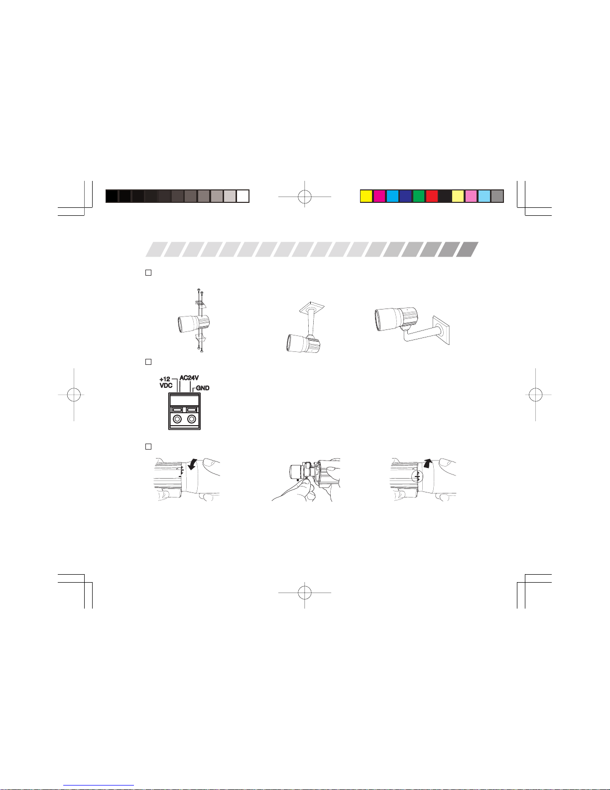
INSTALLATION & ADJUSTMENT
1
Mounting The Camera
2
Power Supply Cable Connection
12V DC: Connect power supply cable to the power input terminal. In case of 12VDC,
make sure of the proper polarity. Improper polarity may cause damage to
the camera.
24V AC: Connect power supply cable to the power input terminal. In case of 24VAC
60Hz, Line Lock mode can be selected by DIP switch in order to synchronize the picture to the AC power supply.
3
Adjustment of View Angle and Focus
Take the lens hood off by turning
it counter-clockwise.
Adjust view angle and focus by
turning the levers. Then tighten
the lock screws.
Align the markings on the lens
hood and camera body. Then turn
the hood clockwise to lock.
Mount the camera with the bracket on a wall or a ceiling.
Ceiling Mount Wall Mount
EG-6
4
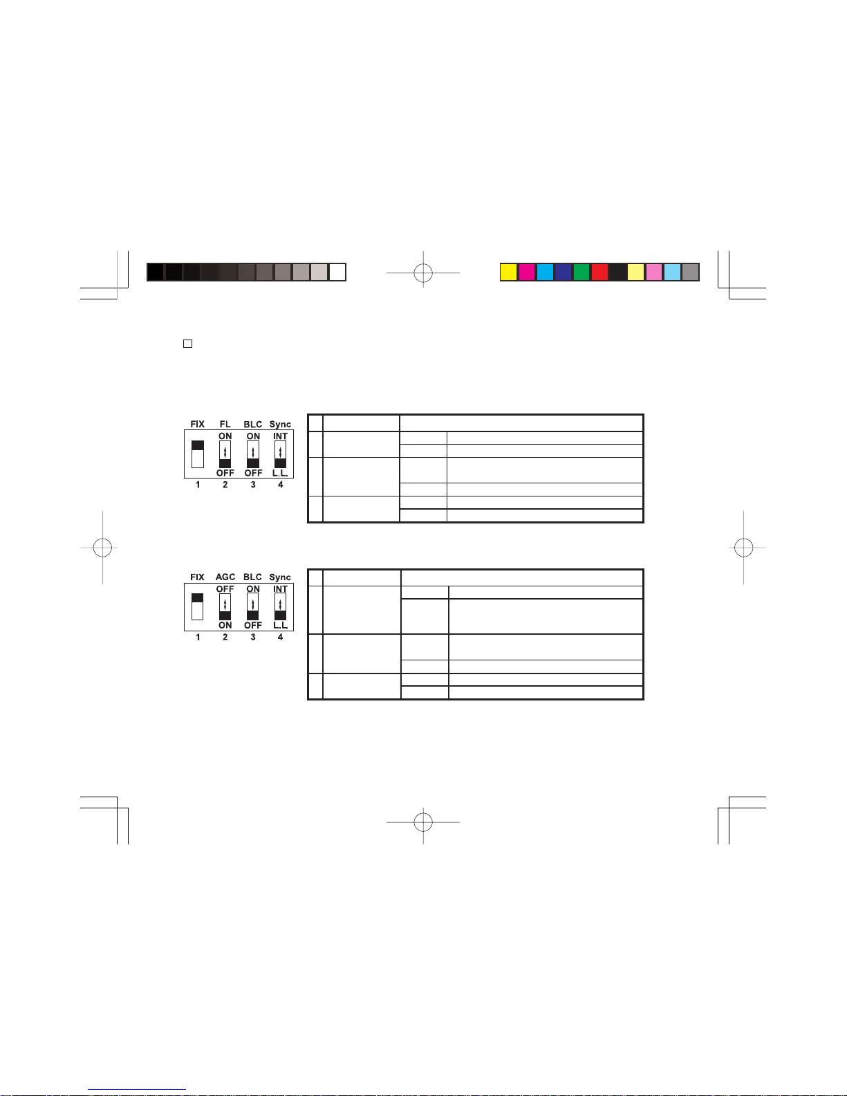
DIP Switch Set Up
Set according to lighting conditions.
Attention: DO NOT change “FIX” switch position from the factory setting.
ZC-L1210NHA (Color)
1 FIX Do not change the switch position from the factory setting.
2
Flickerless
ON Shutter speed to be fixed at 1/100.
(FL)
OFF Normal position
Back Light
ON
Set to this position when a strong light is in the
3
Compensation
back ground.
(BLC)
OFF Normal position
4
Synchronization
INT Internal synchronization mode
Mode
L.L. Line lock mode (24VAC, 60Hz only)
1 FIX Do not change the switch position from the factory setting.
OFF Gain level to be fixed at 4dB.
2
Auto Gain Control
ON
Set to this position to improve camera
(AGC) sensitivity in low light conditions.
Gain level varies from 4dB to 22dB.
Back Light
ON
Set to this position when a strong light is in the
3
Compensation
back ground.
(BLC)
OFF Normal position
4
Synchronization
INT Internal synchronization mode
Mode
L.L. Line lock mode (24VAC, 60Hz only)
ZC-L1210EHA (Black & White)
Factory Setting
Factory Setting
EG-7
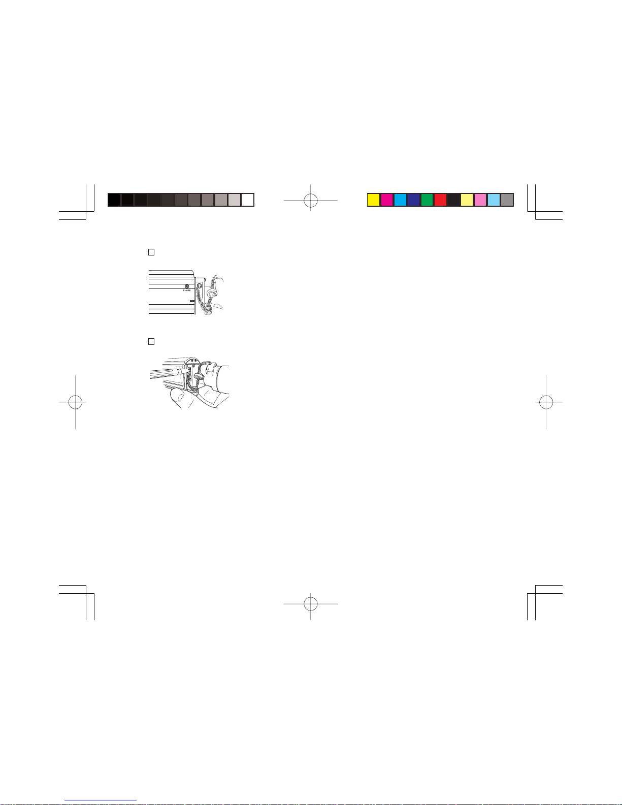
5
Line Phase Adjustment (24VAC 60Hz, Line Lock mode)
6
DC Iris Level Adjustment
If necessary, turn the volume to adjust the line phase.
Set according to lighting conditions.
If necessary, turn the volume to adjust the DC iris level.
Attention: In case of ZC-L1210EHA (Black & White model), set AGC DIP switch to OFF
while adjusting DC iris level.
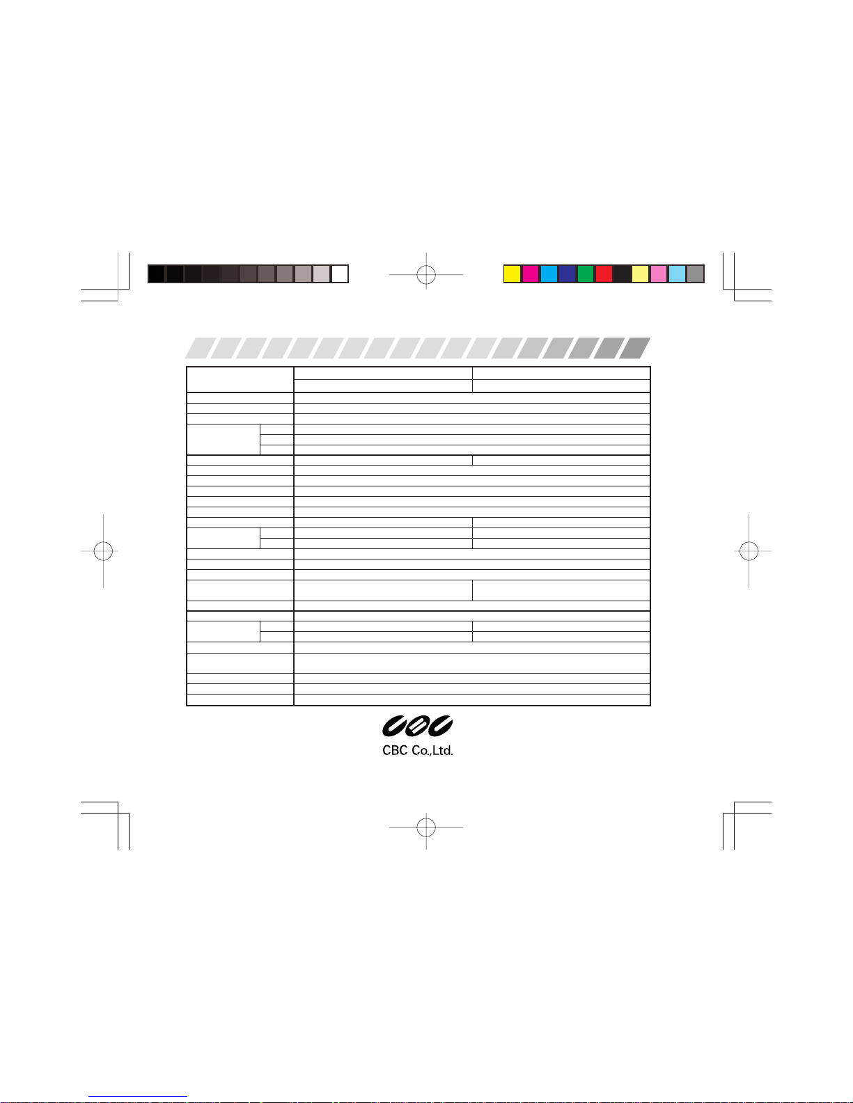
Model ZC-L1210NHA ZC-L1210EHA
Color / High Resolution Black & White / High Resolution
Focal Length 2.8 - 10 mm
Max.Aperture Ratio 1 : 1.2
Iris F1.2 - 360 (DC auto iris)
D 105.8°〜27.0°
Angle of View H 78.2°〜21.6°
V 55.8°〜16.2°
TV System NTSC EIA
Scanning Syetem 2:1 Interlace
Image Sensor 1/4" IT CCD
Effective Elements 768 (H) × 494 (V)
Scanning Frequency (H/V) 15.734 kHz / 59.94 Hz
Video Outputs 1.0 V (p-p) / 75
Resolution (Horizontal) 480 TVL 580 TVL
Min.Illuminance
50IRE 1.5 lx 0.48 lx
30IRE 0.75 lx 0.24 lx
S/N Ratio More than 50 dB (AGC gain : minimum)
γ
Characteristic 0.45
Sync. System INT. / L.L.
Electric Shutter
1/60 sec. Fixed (Flickerless: OFF)
1/60 sec. Fixed
1/100 sec. Fixed (Flickerless: ON)
White Balance ATW –
Power Supply AC 24V ± 10%, 60 Hz ± 1 Hz / DC 12V ± 10 %
Power Consumption
DC 12V 2.0 W 1.6 W
AC 24V 2.1 W, 180 mA 1.8 W, 150 mA
Ambient Temperature Operation : -10°C〜+50°C / Storage : -20°C〜+60°C
Ambient Humidity
(No Condensation)
Operation : 85% RH max. / Storage : 95% RH max.
External Dimensions 55 (W)mm × 61(H) × 122 (D) mm
Weight Approx. 200 g
Adjustment Volume DC iris level , Line phase
Tokyo, Japan
www.GANZ.jp
021-1.2
SPECIFICATIONS
CAMARA CON LENTES INCORPORADOS
MANUAL DE INSTRUCCIONES
SP-2
Gracias por la compra de este producto. Antes de operar la cámara, por favor lea este manual de instrucciones cuidadosamente
para asegurar su uso apropiado. Guarde este manual de instrucciones en un lugar seguro para futura referencia.
CONTENIDO
CARACTERISTICAS ....................................................................................................................................... SP-2
PRECAUCIONES DE SEGURIDAD ...................................................................................................................SP-2
DESCRIPCION DE LAS PARTES ..................................................................................................................... SP-4
INSTALACION Y AJUSTE ............................................................................................................................... SP-5
ESPECIFICACIONES ....................................................................................................................................... SP-8
CARACTERISTICAS
• El lente dinamico de distancia focal variable 4X integrada permite un aplicación versátil e instalación fácil.
• Diseño compacto y de poco peso.
• El filtro de lente previene la incursion de polvo.
• El filtro de lente puede ser sustituido con distintos filtros fabricados en sitios comeciales.(ND/filtro polarizador etc.)
• Acepta la potencia de entrada de 12 VCC o 24VCA. (Conmutación automática)
PRECAUCIONES DE SEGURIDAD
La instalación se debe hacer por personal de servicio calificado o instaladores de sistemas y confirmando todos los
códigos locales.
Este símbolo indica que existe la posibilidad de muerte o peligro para el operador u otras personas.
Para evitar fuego o choque eléctrico, no exponga este producto a la lluvia o humedad.
 Loading...