

Ganz ZC-DWNT8312NXA, ZC-DWT8312NXA, ZC-DWT8312NXA-IR, ZC-DWT8039NXA, ZC-DWNT8312NXA-IR Instruction Manual
...
MODEL
SPECIFICATION
SAFETY PRECAUTIONS
PRODUCT FEATURES
OPTIONS
PARTS DESCRIPTION
Thank you for your purchase of this product. Before operating the product, please read this instruction manual
carefully to ensure proper use of the product. Please store this instruction manual in a safe place for future
reference.
The CE Marking is a Directive Conformity mark of t
(for NTSC models)
(for PAL models)
(for PAL models)
he European Union(EU)
* Unscrew the 4 fixing screws with the L-type tool provided before removing the dome
cover to open the unit for adjustments. Once adjusted, fix the dome cover to the dome
base until it seals tightly using the 4 fixing screws, and refrain from opening and closing
frequently to ensure the best water-proof and condensation free performance.
Outside
Inside
12
OUTDOOR COLOR CAMERA
INSTRUCTION MANUAL
ZC-DWT8000
SERIES
700TVL High Resolution
Color / Day & Night
2
3
4
5
6
7
13
8
9
11
10
1
1. UTP Board (ZCA-UP8T)
2. Service Monitor Cable (ZCA-SM8)
3. Pendant Mount (ZCA-PM8T)
4. Mounting Adaptor Ring (ZCA-FM8T)
5. Lens variations
Please contact your dealers for more details of the following options.
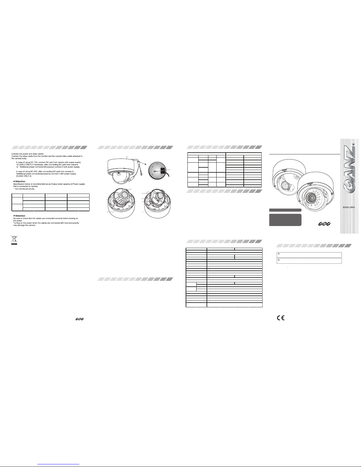
CONNECTING THE CABLES
About disposal of your old appliance, please contact your city office, waste disposal service or the shop where you purchased the product.
hcnerF/siaçnarF
Élimination de votre ancien appareil
1. Ce symbole, représentant une poubelle sur roulettes barrée d'une croix, signifie que le produit est couvert par la directive européenne
2002/96/EC. 2. Tous les produits électriques et électroniques doivent être éliminés séparément de la chaîne de collecte municipale des
ordures, par l’ intermédiaire des installations de collecte prescrites et désignées par le gouvernement ou les autorités locales. 3. Une
élimination conforme aux instructions aidera à réduire les conséquences negatives et risques éventuels pour ironnement et la santé
humaine. 4. Pour plus d'informations concernant l'élimination de votre ancien appareil, veuillez contacter votre mairie, le service des
ordures ménagères ou encore le magasin où vous avez acheté ce produit.
Deutsch/German
Entsorgung von Altgeräten
1. Wenn dieses Symbol eines durchgestrichenen Abfalleimers auf einem Produkt angebracht ist, unterliegt dieses Produkt der
europäischen Richtlinie 2002/96/EC. 2. Alle Elektro- und Elektronik-Altgeräte müssen getrennt vom Hausmüll über die dafür staatlich
vorgesehenen Stellen entsorgt werden. 3. Mit der ordnungsgemäßen Entsorgung des alten Geräts vermeiden Sie Umweltschäden und
eine Gefährdung der rsönlichen Gesundheit. 4. Weitere Informationen zur Entsorgung des alten Geräts erhalten Sie bei der Stadtverwaltung, beim Entsorgungsamt oder in dem Geschäft, wo Sie das Produkt erworben haben.
Italiano/Italian
RAEE: SMALTIMENTO DELLE VOSTRE VECCHIE APPARECCHIATURE
1. Quando il simbolo del “Cassonetto Barrato” è apposto su un prodotto, significa che lo stesso può ricadere nei termini previsti dalla
Direttiva Europea nr. 2002/96/EC in funzione dell’attuazione definita dalla Legislazione dei singoli stati membri dell’Unione Europea. 2.
Tutti i prodotti elettrici ed elettronici dovrebbero essere smaltiti separatamente dai rifiuti municipali, tramite appositi ontenitori, approvati
dall’Amministrazione Comunale o dalle Autorità Locali.
3. Il corretto smaltimento delle vostre vecchie apparecchiature, contribuirà a prevenire possibili conseguenze di impatto egativo sull’
ambiente e per la salute dell’uomo. 4. Per maggiori informazioni circa lo smaltimento delle vostre vecchie apparecchiature, siete pregati di
contattare l’ufficio municipale della vostra città, il servizio di smaltimento rifiuti o il punto vendita nel quale avete acquistato il prodotto.
Polski/Polish
Utylizacja starych urządzeń
1. Kiedy do produktu dołączony jest niniejszy przekreślony symbol kołowego pojemnika na śmieci, oznacza to, że produkt jest objęty
europejską dyrektywą 2002/96/EC. 2. Wszystkie elektryczne i elektroniczne produkty powinny być utylizowane niezależnie od odpadów
miejskich, zwykorzystaniem przeznaczonych do tego miejsc składowaniawskazanych przez rząd lub miejscowe władze. 3. Właściwy
sposób utylizacji starego urządzenia pomoże zapobiec potencjalnie negatywnemu wpływowi na zdrowie i środowisko. 4. Aby uzyskać
więcej informacji o sposobach utylizacji starych urządzeń, należy skontaktować się z władzami lokalnymi, przedsiębiorstwem zajmującym
się utylizacją odpadów lub sklepem, w którym produkt zostałkupiony.
Português/Portuguese
Eliminação do seu antigo aparelho
1. Quando este símbolo de latão cruzado estiver afixado a um produto, significa que o produto é abrangido pela Directiva Europeia
002/96/EC. 2. Todos os produtos eléctricos e electrónicos devem ser eliminados separadamente da coleta de lixo municipal através de
pontos de recolha designados, facilitados pelo governo ou autoridades locais. 3. A eliminação correcta do seu aparelho antigo ajuda a
evitar potenciais onsequências negativas para o ambiente e para a saúde humana. 4. Para obter informaçõs mais detalhadas acerca da
eliminação do seu aparelho antigo, contacte as autoridades locais, um service de eliminação de resíduos ou a loja onde comprou o
produto.
Español/Spanish
Cómo deshacerse de aparatos eléctricos y electrónicos viejos
1. Si en un producto aparece el símbolo de un contenedor de basura tachado, significa que éste se acoge a la Directiva 2002/96/EC.2.
Todos los aparatos eléctricos o electrónicos se deben desechar de forma distinta del servicio municipal de recogida de basura, a través
de puntos de recogida designados por el gobierno o las autoridades locales. 3. La correcta recogida y tratamiento de los dispositivos
inservibles contribuye a evitar riesgos potenciales para el medio ambiente y la salud pública. 4. Para obtener más información sobre
cómo deshacerse de sus aparatos eléctricos y electrónicos viejos, póngase en contacto con su ayuntamiento, el servicio de recogida de
basuras o el establecimiento donde adquirió el producto.
English
Disposal of your old appliance
1. When this crossed-out wheeled bin symbol is attached to a product it means the products covered by the European
Directive 2002/96/EC. 2. All electrical and electronic products should be disposed of separately from the municipal waste
stream via designated collection facilities appointed by the government or the local authorities. 3. The correct disposal of
your old appliance will help prevent potential negative consequences for the environment and human health. 4. For more
detailed information
CBC Co.,Ltd
Tokyo, Japan
www.GANZ.jp
※
The specifications and/or appearance of the product may change without prior notice
Edit : ZC-DT8000_IR-700-X-DUAL V_140612_V1
(1) Use only AC24V power suppy marked class 2 or +DC12V regulated power supply marked class 2.
(2) To prevent fire of electrical shock, UL listed class 2 wiring should be used for the DC12V or AC24V input terminal.
(3) Be sure to connect each lead to the appropriate terminal, wrong connection may cause malfunction and/or
damage to the camera.
(4) Do not attempt to aim the camera at the sun or other extremely bright objects that cause smear to appear
irrespective of whether the camera is operating or not. This can damage the CCD(Charge Coupled Device).
(5) Do not place the camera in the following location.
1) Locations subject to extremely high or low temperature.
(Operating temperature range : -20'C to +50'C {-4'F to 122'F}
*Optional Heater models -40’C to + 50’C{-40’F to 122’F})
(Storage temperature range : -20'C to +60'C{-4'F to 140'F})
2) Locations where there are large amounts of water vapor and steam.
(6) Ensure the location selected near equipment that emits a strong electromagnetic field, some irregularity such as
noise on the monitor screen may happen.
(7) When this camera is installed near equipment that emits a strong electromagnetic field, some irregularity such
as noise on the monitor screen may happen.
(8) Be sure to use screws suitable for the type of material to which the camera is being mounted.
(9) Do not allow the camera to be subjected to strong impacts or shocks. The camera could be damaged by improper
handling or storage.
(10) Never attempt to disassemble or modify the camera.
(11) If an abnormality should occur, immediately turn off the power and consult your dealer.
This device complies with Part 15 of the FCC Rules, Operation is subject to the following two conditions:(1)This
device may not cause harmful interference, and (2)This device must accept any interference received, including
interference that may cause undesired operation.
This symbol indicates that there is a possibility of death or damage to operator or others.
To prevent fire or electric shock, do not expose this product to rain or moisture.
WARNING
This symbol indicates that there is a possibility of injury or damage to equipment.
The installation should be made by a qualified service person and should conform to all local codes.
Attention
AC
DC
Standard
IR Model
148mm(W) x 128mm(H)
Standard Type : Approx. 1000g, IR Type : A pprox. 1100g
Multi Tact Switch for OSD Control, Slide Switch for Sync. System
Accessories
Self-tapping Screw : 3ea, Template : 1ea, Wrench : 1ea,
Instruction Manual : 1ea, Additional Power Connector : 1ea
AC24V±10% 60HZ±1Hz AC24V±10% 50HZ±1Hz
DC 12V±10%
3.0 Watt(AC24V), 2.7 Watt(DC12V)
Operation : -10℃ to +50℃ / Storage : -20℃ to +60
℃
Operation : Max 85%RH / Storage : Max 95%RH
Ambient Humidity
External Dimensions
Weight
Switches
Power Supply
Ambient Temperature
Power
Consumption
6.1 Watt(AC24V), 5.9 Watt(DC12V)
15.734kHz(H) x 59.94Hz(V)
Gamma Characteristic
Sync. System
Electronic Shutter
Back Light
Scanning Frequency
Video Output
Horizontal Resolution
Minimum Illumination(F1.4)
Day / Night
S/N Ratio
0.45
Internal / Line Lock (Selectable)
White Balance ATW, PUSH, USER1, USER2, MANUAL, PUSH LOCK (Selectable)
BLC, HLC, ATR-EX, WDR, OFF (Selectable)
1/60 sec, FLK, 1/60-1/100,000 (Selectable)
1/50 sec, FLK, 1/50-1/100,000 (Selectable)
15.625kHz(H) x 50.00Hz(V)
1.0Vp-p/75
Ω
More than 700 TVL
Standard Type : D-DN:0.4lx T-DN:0.04lx, IR Type : 0 lx (B/W Model/LED ON)
Digital or True Day / Night
More than 50dB (at minimum AGC gain)
TV System NTSC PAL
Scanning System
Image Sensor
Effective Elements
2:1 Interlace
1/3" Type Interline Transfer CCD (Sony HAD II CCD)
976(H) x 494(V)
976(H) x 582(V)
-. 1/3 SONY Super HAD-II CCD
-. Photocell Activate IR Lights at Night (For IR Model)
-. True or Digital Day & Night
-. Auto-sensing DC12V/AC24V Dual-Voltage Operation
-. True WDR (Wide Dynamic Range)
-. Back Light Compensation
-. High Light Compensation
-. Motion Detection
-. Privacy Masking
-. 3D Digital Noise Reduction (3DNR)
-. Lens Shading Compensation
-. Low Power Consumtion
-. Multi Tact Switch for OSD Control
-. IR Optimizer (For IR Model)
-. Sense Up (Slow shutter)
-. Compatible for UTC Communication
-. IP67 Rating for All Weather performance
Type
Standard
IR
550mA±10%
500mA±10%
DC12V
DC 12V±10%
AC24V
AC 24V±10%
Input Power
Voltage
Current
DC12V
AC24V
DC 12V±10%
AC 24V±10%
300mA±10%
300mA±10%
1. Bottom Cover
2. Top Cover
3. Video Output Connector
4. Power Input Jack
5. Elastic Band for Easy installation
6. Middle Cover
7. Focus and View Angle Adjust Lever
8. Service Jack Socket
9. Multi Tact Switch for OSD
10. Breakable hole for UTP Cable
11. Breakable 4 Holes for Gang box
12. Slide Switch for Sync. System
13. LED Cover (for IR Model)
(IR Model) (Standard Model)
Focal Length D/N Aperture View Angle
Digital
True
Digital
True
Digital
True
Lens Specification
Models (Standard DC12/AC24V Dual-Voltage)
NTSC
PAL
ZC-DWT8039NXA
ZC-DWNT8039NXA
ZC-DWT8039PXA
ZC-DWNT8039PXA
3~9mm
1:1.2~2.1
1:1.4~2.4
90~31.8
Digital
True
ZC-DWNT8312NXA-IR
ZC-DWNT8312PXA-IR
ZC-DWT8312NXA
ZC-DWT8312PXA
ZC-DWT8312NXA-IR
ZC-DWT8312PXA-IR
ZC-DWNT8312NXA
ZC-DWNT8312PXA
3.3~12mm 1:1.4~2.9 89.8~23.9
Digital
True
ZC-DWT8256NXA
ZC-DWT8256PXA
2.5~6mm 1:1. 2~1.6 111.6~47.3
ZC-DWNT8256NXA
ZC-DWNT8256PXA
9-22mm
5-50mm
1:1.4~1.6 23.1~13.1
ZC-DWT8922NXA
ZC-DWT8922PXA
ZC-DWNT8922NXA
ZC-DWNT8922PXA
1:1.8~1.8 51.5~6.5
ZC-DWT8550NXA
ZC-DWT8550PXA
ZC-DWNT8550NXA
ZC-DWNT8550PXA
SCENE SELECT
PICT ADJUST
EZOOM
DIS
PRIVACY MASK
MOTION DET
SYSTEM SETTING
LANGUAGE
MAINTENANCE
EXIT
MOTION DETECTION
SYNC Mode, Lens, Flip, LCD/CRT, Communication, CAMERA ID
ENG, ESPANOL, PYCCKNN, PORTUGUES, DEUTSCH, FRANCAIS, 中文, 日本語
W.PIX MASK, CAMERA Reset
SAVE, NOT SAVE, CANCEL
OSD MENU FUNCTION
Normal, Indoor, Outdoor, Backlight, ITS, Custom
Brightness, Contrast, Sharpness, Hue, Color Gain
MAG, PAN, TILT
ON / O
FF
PRIVACY MASK SETUP
SETUP MENU
⇦ 1/2 ⇨
SCENE SELECT NORMAL ↲
PIC ADJUST ↲
EZOOM OFF
DIS OFF
PRIVACY MASK ↲
MOTION DET OFF
SYS SETTING ↲
EXIT ↲
1) MAIN MENU 2) ADVANCED MENU
Turn the Switch toward Left or Right side, Select Each mode.
ADVANCED MENU
⇦ 2/2 ⇨
LENS SHD COMP OFF
DEFOG ON↲
FLK LESS OFF↲
ANTI CR OFF
RETURN↲
SETUP MENU
⇦ 2/2 ⇨
LANGUAGE ENGLISH
VERSION 1.0
MAINTENANCE ↲
EXIT ↲
・SCENE SELECT
・PICT ADJUST
・EZOOM
・DIS : Digital Image Stabilizer
・PRIVACY MASK
・MOTION DET
・SYS SETTING
・LANGUAGE
・VERSION
・MAINTENANCE
・EXIT SAVE
NOTSAVE
CANCEL
BACK
ADVANCED MENUNORMAL
INDOOR
OUTDOOR
BACKLIGHT
ITS
CUSTOM
・SUTTER /AGC
・WHITE BAL
・HLC / BLC
・WDR / ATR-EX
・DAY / NIGHT
・IR OPTMIZER
ATW
(PUSH)
(USER1)
(USER2)
(MANUAL)
(PUSHLOCK)
OFF
HLC
(BLC)
CONTRAST
CLEARFACE
AUTO
DAY
NIGHT
BURST
DELAYCNT
DAY->NIGHT
NIGHT->DAY
AUTO
MANUAL
AE LEVEL
AGC MAX
SENS UP
BRIGHTNESS
CONTRASY
SHARPNESS
HUE
COLOR GAIN
SYNC MODE
LENS
FLIP
LCD / CRT
COMMUNICATION
CAMERA ID
W.PIX MASK
CAMERA RESET
AUTO
MANUAL
MANUAL
AUTO
DATA CLEAR
☞ATTENTION
・Simplymaketheadjustmentinthefollowing
ordertohelpmakethefocusingeasier.
☞ATTENTION
・YoumayexitfromOSDeitherbySAVE,NOTSAVEtokeep,delete,ortemporarily
holdthechangesthatyoumade.
-SelectMANUAL
-Adjustlensfocuswell
-ThenreturntoAUTO
ADVANCED MENU
⇦ 1/2 ⇨
SHUTTER/AGC AUTO ↲
WHITE BAL ATW↲
HLC/BLC OFF
WDR/ATR-EX WDR↲
DNR ↲
DAY/NIGHT AUTO
IR OPTMIZER ↲
RETURN ↲
・LENS SHD COMP
・DEFOG
・FLK LESS
・ANTI CR
OFF
ON
AUTO
OFF
ON
AUTO
:AntiColorRolling
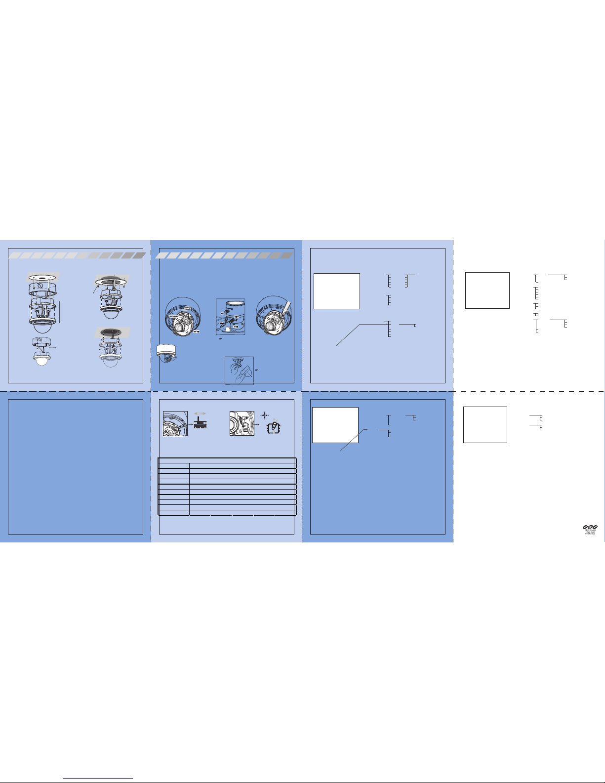
ADJUSTMENT
1)
3)
2)
☞Attention
The picture image may deteriorate when
the lens is leaned toward ceiling or wall
to view through the circled vertical area
and the effect may vary depending on the
view angles.
1. Direction and Lens
The camera body is set in a tri-axial mounting
allowing movement in the pan, tilt and rotational planes.
1) Adjust the direction of the lens so it faces the subject
2) Move the lever to adjust focus and angle of view
3) When you finished adjusting the direction of the lens, tighten the locking screw with a screwdriver.
Direction and Enter Guide
Up
Down
Enter
RightLeft
* L-L : Line Lock
* INT : Internal
INT
L-L
2. Switches
1) Slide Switch for Sync. System 2) Multitack Switch for OSD
Use the
Slide Switch within the camera
Use the
Multi Tact Switch within the camera
3. OSD MENU
* Surface mount
This section explains how to install the unit where cables are running through the
interior of the ceiling or wall.
1. Drilling holes in the ceiling or wall: Use the template included to mark out the
position on the ceiling or wall where you want to install the unit.
2. When running cables through the interior of the ceiling or wall : Use the template,
and drill two or three holes for screws used to attach the camera body and one hole
for the cables (Cables).
* Flush mount
- Embedding in the ceiling or wall
Be sure to use the Mouting Adaptor Ring when embedding the unit in the ceiling or wall
1. Drilling holes in the ceiling or wall : Use the template included to mark out
the position on the ceiling or wall where you want to install the unit.* Use the template,
drill 4 holes for screw used to attache the Mounting Adaptor Ring. Then, follow the
perforations on the template and cut out a hole to embed the camera body.
2. Attaching the Mounting Adaptor ring : Attach the adaptor ring to the ceiling or wall to
which you want to attach the camera body. Please use fixing screws suitable for the
material of the ceiling or wall when attaching the camera body. We recommend using
screws with a 4mm diameter.
3. Attaching the camera body : Remove the surface mount cover from the camera
body. Remove the body cover and attached camera body to the Mounting Adapter Ring.
- Attaching to gangbox
1. Remove the surface mount cover from the camera body.
2. Attaching the camera body : Attach the camera body to the gangbox.
Please use screws that are suitable for the gang box.
(Use breakable holes on the camera body bottom)
INSTALLATION
(embedding in ceiling or wall)
(Attaching to a gang box)
Surface mount
Flush mount
* Use the elastic band to
hang the camera unit
upon necessity for the
installation.
WARNING : Do not
release your hands
from the camera
unit until securing it.
* Mounting
Adaptor Ring
(optional)
☞Attention
Please use fixing screws suitable for the material of the ceiling or wall when attaching the camera body.
The mounting screws provided are not recommended to use at a conditionns.
* Camera Unit
t is not recommended to view through the circledd vertical
area especiallly witth LED light turned on as the picture
image is subject to a LED light reflection.
Since such image deterionration is normal, installers are
encouraged to check the image under LED-ON environment
at the time of installation in order to avoid unexpected image
deterioration.
Attention
The 5-50mm model requires a focusing procedure
with the dome cover being placed in front as shown
in the illustration. The picture may get blurry if the
focusing is done without this procedure.
The positions of focus and
zoom adjustment levers are
reversed on 9-22mm and
5-50mm models.
Attention
 Loading...