

Ganz ZC-BNX4312NHA, ZC-BT Series, ZC-BX Series, ZC-BT4312NHA User Manual
EG-2
This symbol indicates that there is a possibility of injury or damage to
equipment.
(1) Use only 24V AC power supply marked class 2 or +12V DC regulated power
supply marked class 2.
(2) To prevent fi re or electrical shock, UL listed class 2 wiring should be used for the
12V DC or 24V AC input terminal.
(3) Be sure to connect each lead to the appropriate terminal. Wrong connection may
cause malfunction and / or damage to the video camera.
(4) Do not attempt to aim the camera at the sun or other extremely bright objects that
cause smear to appear irrespective of whether the camera is operating or not. This
can damage the CCD (Charge Coupled Device).
(5) Do not place the camera in the following locations.
1
Locations subject to extremely high or low temperatures.
(Operating temperature range: -10°C to +50°C {14°F to 122°F})
(Storage temperature range: -20°C to +60°C {-4°F to 140°F})
2
Locations where there are large amounts of water vapor and steam.
(6) Ensure the location selected is suffi ciently strong enough to support the weight of
the camera and is free from vibration.
(7) When this camera is installed near equipment that emits a strong electromagnetic
fi eld, some irregularity such as noise on the monitor screen may happen.
(8) Be sure to use screws suitable for the type of material to which the camera is
being mounted.
(9) Do not allow the camera to be subjected to strong impacts or shocks. The camera
could be damaged by improper handling or storage.
(10) Never attempt to disassemble or modify the camera.
(11) If an abnormality should occur, immediately turn off the power and consult your
dealer.
This device complies with Part 15 of the FCC Rules. Operation is subject to following
two conditions:
(1) This device may not cause harmful interference.
(2) This device must accept any interference received, including interference that may
cause undesired operation.
Thank you for your purchase of this product. Before operating the product,
please read this instruction manual carefully to ensure proper use of the
product. Please store this instruction manual in a safe place for future
reference.
CONTENTS
PRODUCT FEATURES ............................................................................ EG-2
SAFETY PRECAUTIONS ......................................................................... EG-2
PARTS DESCRIPTION ............................................................................ EG-3
INSTALLATION AND ADJUSTMENT ...................................................... EG-5
SPECIFICATIONS .................................................................................... EG-9
PRODUCT FEATURES
High resolution 540TVL and low light performance surveillance camera with a built-in
1/3” CCD.
A stylish all weather outdoor housing ideal for installations requiring a discreet
appearance and outdoor performance.
Integrated Computar varifocal lens allows for versatile applications and easy
installation.
Outstanding 0 lux performance with built in IR LEDs.
Day/Night feature switches to B/W image at night.
Photocell activates IR light at night.
Easy cable management with cable feed-through bracket.
Built-in 20 LED lights.
IP66 rating for all weather conditions (ZC-BT series).
24V AC / 12V DC Auto Sensing Dual Voltage.
SAFETY PRECAUTIONS
The installation should be made by a qualifi ed service person and should conform to all
local codes.
This symbol indicates that there is a possibility of death or damage to operator
or others.
To prevent fi re or electric shock, do not expose this product to rain or moisture.
EG-3
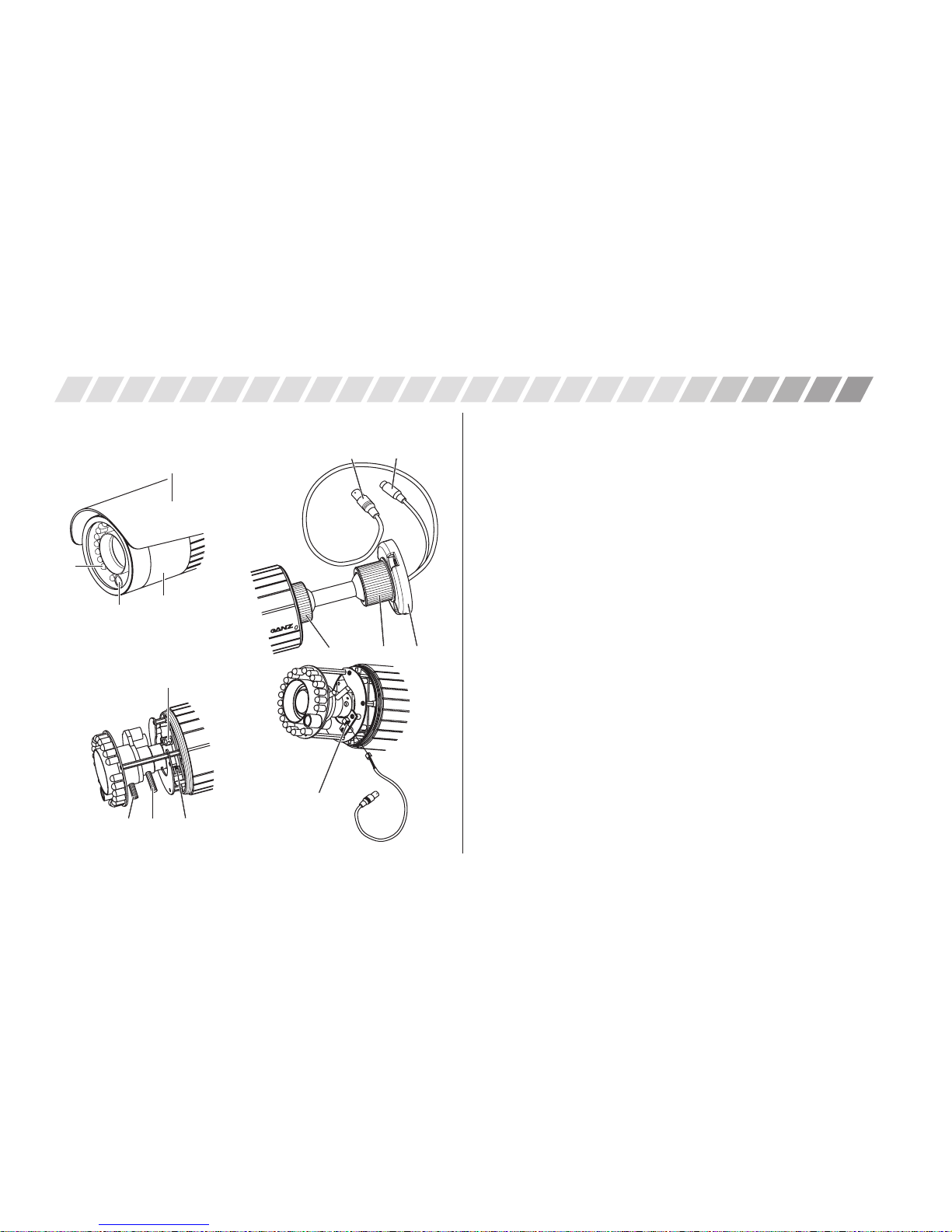
1. ZC-BT series
PARTS DESCRIPTION
* Unscrew the Front Cover counterclockwise to open the unit for adjustments. Once adjusted,
screw the Front Cover back and tighten it clockwise, and refrain from opening and closing
frequently to ensure the best waterproof and condensation free performance.
1
IR LED
2
Photo sensor
3
Front cover
4
Sunshield
5
Focus adjustment lever (Lock screw)
6
View angle adjustment lever (Lock screw)
7
DIP SW (AGC ON/OFF, FL ON/OFF, BLC ON/OFF, ALCELC)
8
DC iris level adjustment volume
9
Service jack socket (*for ZC-BT series only)
bk
Locking ring (Body)
bl
Locking ring (Bracket)
bm
Mounting base
bn
BNC connector for video output
bo
DC jack for power input (12V DC or 24V AC)
4
3
2
5 67
8
bn bo
bk bl bm
Outside
Inside
Bracket
Service connector (*optional)
9
1
EG-4
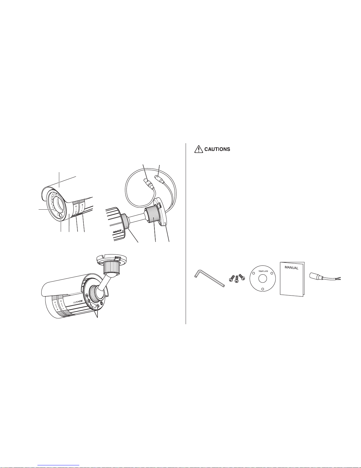
2. ZC-BX series
1
IR LED
2
Photo sensor
3
Front cover
4
Sunshield
5
Exterior focus adjustment ring
6
Exterior view angle adjustment ring
7
Locking ring (Body)
8
Locking ring (Bracket)
9
Mounting base
bk
BNC connector for video output
bl
DC jack for power input (12V DC or 24V AC)
bm
Magnetic control bolt (MCB) for ALCELC and BLC ON/OFF
● ZC-BX housing is designed to be adjusted externally. ALCELC
adjustment and BLC ON/OFF can be made only by Magnetic Control Bolt
(MCB).
Once Front Cover is unlocked for any reason, its outdoor performance
cannot be guaranteed.
● Wrench: 1ea
● Bracket screw: 3ea
● Template: 1ea
● Instruction manual: 1ea
● Additional power connector: 1ea
3. Accessories
1
4
23 56
bk
bl
7 89
bm
Outside Bracket
Rear
 Loading...