

Ganz ZCA-GT100 Installtion Instruction
Installation Guide
Preface
The information provided in this manual was current when published. The company reserves the
right to revise and improve its products. All specifications are subject to change without notice.
Notice
To work with the PTZ cameras, any installer or technician must have the following
minimum qualifications:
• A basic knowledge of CCTV systems and components
• A basic knowledge of electrical wiring and low-voltage electrical connections
• Thorough familiarity with the contents of this manual
Important Information
Before proceeding, please read and observe all instructions and warnings in this
manual. Retain this manual with the original bill of sale for future reference and, if
necessary, warranty service. When unpacking your unit, check for missing or
damaged items. If any item is missing, or if damage is evident, DO NOT INSTALL OR
OPERATE THIS PRODUCT. Contact your dealer for assistance.
Copyright
Under copyright laws, the contents of this user manual may not be copied,
photocopied, translated, reproduced or replicated in any electronic medium or
machine-readable format, in whole or in part, without the prior written permission of
CBC Co. Ltd.
©Copyright2006CBC Co. Ltd.
Regulation
This device complies with Part 15 of the FCC Rules. Operation is subject to the
following two conditions:
(1) this device may not cause harmful interference, and (2) this device must accept
any interference received, including interference that may cause undesired
operation.
1

Installation Guide
English
Disposal of your old appliance
1. When this crossed-out wheeled bin symbol is attached to a product it means the
product is covered by the European Directive 2002/96/EC.
2. All electrical and electronic products should be disposed of separately from the
municipal waste stream via designated collection facilities appointed by the
government or the local authorities.
3. The correct disposal of your old appliance will help prevent potential negative
consequences for the environment and human health.
4. For more detailed information about disposal of your old appliance, please contact
your city office, waste disposal service or the shop where you purchased the product.
Français/French
Élimination de votre ancien appareil
1. Ce symbole, représentant une poubelle sur roulettes barrée d'une croix, signifi e
que le produit est couvert par la directive européenne 2002/96/EC.
2. Tous les produits électriques et électroniques doivent être éliminés séparément de
la chaîne de collecte municipale des ordures, par l’
intermédiaire des installations de collecte prescrites et désignées par le
gouvernement ou les autorités locales.
3. Une élimination conforme aux instructions aidera à réduire les conséquences
negatives et risqueséventuelspour l'environnement et la
santé humaine.
4. Pour plus d'informations concernant l'élimination de votre ancien appareil, veuillez
contacter votre mairie, le service des ordures ménagères ou encore le magasin où
vous avez acheté ce produit.
Deutsch/German
Entsorgung von Altgeräten
1. Wenn dieses Symbol eines durchgestrichenen Abfalleimers auf einem Produkt
angebracht ist, unterliegt dieses Produkt der europäischen Richtlinie 2002/96/EC.
2. Alle Elektro- und Elektronik-Altgeräte müssen getrennt vom Hausmüll über die
dafür staatlich vorgesehenen Stellen entsorgt werden.
3. Mit der ordnungsgemäßen Entsorgung des alten Geräts vermeiden Sie
Umweltschäden und eine Gefährdung der persönlichen Gesundheit.
4. Weitere Informationen zur Entsorgung des alten Geräts erhalten Sie bei der
2

Installation Guide
Stadtverwaltung, beim Entsorgungsamt oder in dem Geschäft, wo Sie das Produkt
erworben haben.
Italiano/Italian
INFORMAZIONE AGLI UTENTI
Ai sensi dell’art. 13 del Decreto Legislativo 25 luglio 2005, n. 151 "Attuazione delle
direttive 2002/95/CE, 2002/96/CE e 2003/108/CE, relative alla riduzione dell'uso di
sostanze pericolose nelle apparecchiature elettriche ed elettroniche, nonché allo
smaltimento dei rifiuti"
Il simbolo del cassonetto barrato riportato sull’ apparecchiatura o sulla sua
confezione indica che il prodotto alla fi ne della propria vita utile deve essere raccolto
separatamente dagli altri rifiuti.
La raccolta differenziata della presente apparecchiatura giunta a fi ne vita è
organizzata e gestita dal produttore. L’utente che vorrà disfarsi della presente
apparecchiatura dovrà quindi contattare il produttore e seguire il sistema che questo
ha adottato per consentire la raccolta separata dell'apparecchiatura giunta a fi ne
vita.
L’adeguata raccolta differenziata per l’avvio successivo dell’apparecchiatura
dismessa al riciclaggio, al trattamento e allo smaltimento ambientalmente
compatibile contribuisce ad evitare possibili effetti negativi sull’ambiente e sulla
salute e favorisce il reimpiego e/o il riciclo dei materiali di cui è composta
l’apparecchiatura.
Lo smaltimento abusivo del prodotto da parte del detentore comporta l’applicazione
delle sanzioni amministrative previste dalla normativa vigente.
Polski/Polish
Utylizacja starych urządzeń
1. Kiedy do produktu dołączony jest niniejszy przekreślony symbol kołowego
pojemnika na śmieci, oznacza to, że produkt jest objęty europejską dyrektywą
2002/96/EC.
2. Wszystkie elektryczne i elektroniczne produkty powinny być utylizowane
niezależnie od odpadów miejskich, z wykorzystaniem przeznaczonych do tego
miejsc składowania wskazanych przez rząd lub miejscowe władze.
3. Właściwy sposób utylizacji starego urządzenia pomoże zapobiec potencjalnie
negatywnemu wpływowi na zdrowie i środowisko.
4. Aby uzyskać więcej informacji o sposobach utylizacji starych urządzeń, należy
skontaktować się z władzami lokalnymi, przedsiębiorstwem zajmującym się
utylizacją odpadów lub sklepem, w którym produkt został kupiony.
3

Installation Guide
Português/Portuguese
Eliminação do seu antigo aparelho
1. Quando este símbolo de latão cruzado estiver afi xado a um produto, signifi ca
que o produto é abrangido pela Directiva Europeia 2002/96/EC.
2. Todos os produtos eléctricos e electrónicos devem ser eliminados
separadamente da coleta de lixo municipal através de pontos de recolha designados,
facilitados pelo governo ou autoridades locais.
3. A eliminação correcta do seu aparelho antigo ajuda a evitar potenciais
consequências negativas para o ambiente e para a saúde humana.
4. Para obter informaçõs mais detalhadas acerca da eliminação do seu aparelho
antigo, contacte as autoridades locais, um service de eliminação de resíduos ou a
loja onde comprou o produto.
Español/Spanish
Cómo deshacerse de aparatos
eléctricos y electrónicos viejos
1. Si en un producto aparece el símbolo de un contenedor de basura tachado, signifi
ca que éste se acoge a la Directiva 2002/96/EC.
2. Todos los aparatos eléctricos o electrónicos se deben desechar de forma distinta
del servicio municipal de recogida de basura, a través de puntos de recogida
designados por el gobierno o las autoridades locales.
3. La correcta recogida y tratamiento de los dispositivos inservibles contribuye a
evitar riesgos potenciales para el medio ambiente y la salud pública.
4. Para obtener más información sobre cómo deshacerse de sus aparatos eléctricos
y electrónicos viejos, póngase en contacto con su ayuntamiento, el servicio de
recogida de basuras o el establecimiento donde adquirió el producto.
Русско/Russian
Избавление вашего старого прибора
Этот символ на продукте или его упаковке означает, что данный продукт
нельзя подвергать утилизации вместе с бытовыми отходами в соответствии с
Директивой 2002/96/EC. Его нужно передать в соответствующий пункт сбора
для переработки электрического и электронного оборудования. Должная
переработка этого продукта позволит обеспечить отсутствие негативных
последствий для окружающей среды и человеческого здоровья, которые могут
возникнуть при выбрасывании продукта в мусорную корзину. Переработка
материалов позволяет сохранять природные ресурсы.
Для получения подробных сведений о переработке этого продукта обратитесь
в городской офис компании, службу ликвидации бытовых отходов или магазин,
где был приобретен продукт.
4

Installation Guide
Cautions
• Handle the camera carefully
Do not abuse the camera. Avoid striking, shaking, etc. The camera could be
damaged by improper handing or storage.
• Do not disassemble the camera
To prevent electric shock, do not remove screws or covers. There are no user
serviceable parts inside. Ask a qualified service person for servicing.
• Do not block cooling holes on the bracket
This camera has a cooling fan inside. Blocking the cooling holes leads to build up
of heat the camera and may cause malfunction.
• Do not operate the camera beyond the specified temperature, humidity or
power source ratings
Use the indoor camera under conditions where temperature is between 0~40°C
(32~104°F), outdoor camera between -50~50°C (-58~12 2°F), and humidity is
below 90%.
• Do not use strong or abrasive detergents when cleaning the camera body
Use a dry cloth to clean the camera when dirty. In case the dirt is hard to remove,
use a mild detergent and wipe gently.
• Never face the camera towards the sun
Do not aim the camera at bright objects. Whether the camera is in use or not,
never aim it at the sun or other extremely bright objects. Otherwise, the camera
may be smeared or damaged.
5

Installation Guide
Table of Contents
1. Introduction...........................................................................................................................8
2. Package Content.................................................................................................................10
3. PTZ Camera Setups and Cable Connections....................................................................12
3.1 Preparations for PTZ Camera Setups (Indoor Camera) ..................................12
3.2 Preparations for PTZ Camera Setups (Outdoor Camera)................................12
3.3 PTZ Camera Setups........................................................................................15
3.3.1 Switch Definition..................................................................................15
3.3.2 Communication Switch Setting............................................................15
3.3.3 PTZ Camera ID Setting .......................................................................16
3.3.4 PTZ Camera Control Protocol .............................................................16
3.4 Cables and Connections..................................................................................18
3.4.1 Cable Requirements............................................................................18
3.4.2 22-Pin Data Cable...............................................................................18
3.4.3 22-Pin Connector Definition.................................................................19
3.4.4 RS-485 Connector Definition...............................................................20
3.5 Cable Wiring and Connection..........................................................................21
4. PTZ Camera Installation......................................................................................................22
4.1 PTZ Camera Dimension..................................................................................22
4.2 Optional Accessories.......................................................................................23
4.3 Ceiling Mount...................................................................................................31
4.3.1 Hard-Ceiling Mounting / Indoor............................................................32
4.3.2 In-Ceiling Mounting / Indoor.................................................................35
4.3.3 In-Ceiling Mounting with Ceiling Panel ................................................37
4.3.4 Ceiling Mounting with Straight Tube (ZCA-ST25/ST50).......................38
4.4 Wall Mount.......................................................................................................41
4.4.1 Mini Pendant Mount (ZCA-GT100)......................................................41
4.4.2 Standard Pendent Mount.....................................................................45
4.4.3 Wall Box Mounting (ZCA-WBM) ..........................................................48
4.5 Corner Mount...................................................................................................51
4.5.1 Standard/Mini Corner Mounting Plate (ZCA-CST/MCP)......................51
4.5.2 Corner Thin/Wide Box Mounting (ZCA-CTB/CWB)..............................54
4.6 Pole Mount ......................................................................................................57
4.6.1 Pole Thin/Wide Direct Mounting (ZCA-PTDM/PWDM)........................57
4.6.2 Pole Thin/Wide Box Mounting (ZCA-PTB/PWB)..................................60
5. System Expansion ..............................................................................................................64
5.1 Connecting with Connector Box (Indoor Use)..................................................64
5.2 Connecting with Power Box.............................................................................65
5.3 Repeater Application........................................................................................66
5.4 RS485 Distribution Unit (ZCA-DS4/8/16).........................................................67
6

Installation Guide
6. System Integration.............................................................................................................. 68
6.1 Using Pelco Keyboard.....................................................................................68
6.2 Using Phillips Allegiant Keyboard ....................................................................70
Appendix A: Technical Specification.........................................................................................72
7

1. Introduction
ZC-PT series integrated indoor PTZ Camera is a new subcompact designed to
deliver superb performance and durability with an intelligent and stylish housing that
is suitable in any security and surveillance installation. ZC-PT-XT series is a new
weather resistant integrated outdoor PTZ Camera. Both ZC-PT and ZC-PT-XT
series PTZ Cameras support one cabling for easy installation, and can be integrated
with CCTV products, such as DVRs, Control Keyboards, and CCTV accessories for
a total surveillance solution.
The PTZ Camera provides four models of new generation advanced DSP color
camera:
ZC-PT236 Model: 36× optical zoom / 12× digital magnification
ZC-PT235 Model: 35× optical zoom / 12× digital magnification
ZC-PT230 Model: 30× optical zoom / 12× digital magnification
Installation Guide
ZC-PT226 model: 26× optical zoom / 12× digital magnification
ZC-PT223 model: 23× optical zoom / 12× digital magnification
ZC-PT218 model: 18× optical zoom / 12× digital magnification
General Operation Requirements:
A minimum of one control device is required for operation, such as a control
keyboard, a DVR or a PC. The integrated high speed dome camera contains a
built-in receiver that decodes commands originating from a control device.
The PTZ Camera supports one cabling for easy installation. Large set of built-in
protocols, including GANZ, Pelco, VCL, Philips, AD-422 (Manchester), etc, which
allow the PTZ Camera to be integrated with other suppliers' surveillance systems.
8
Installation Guide
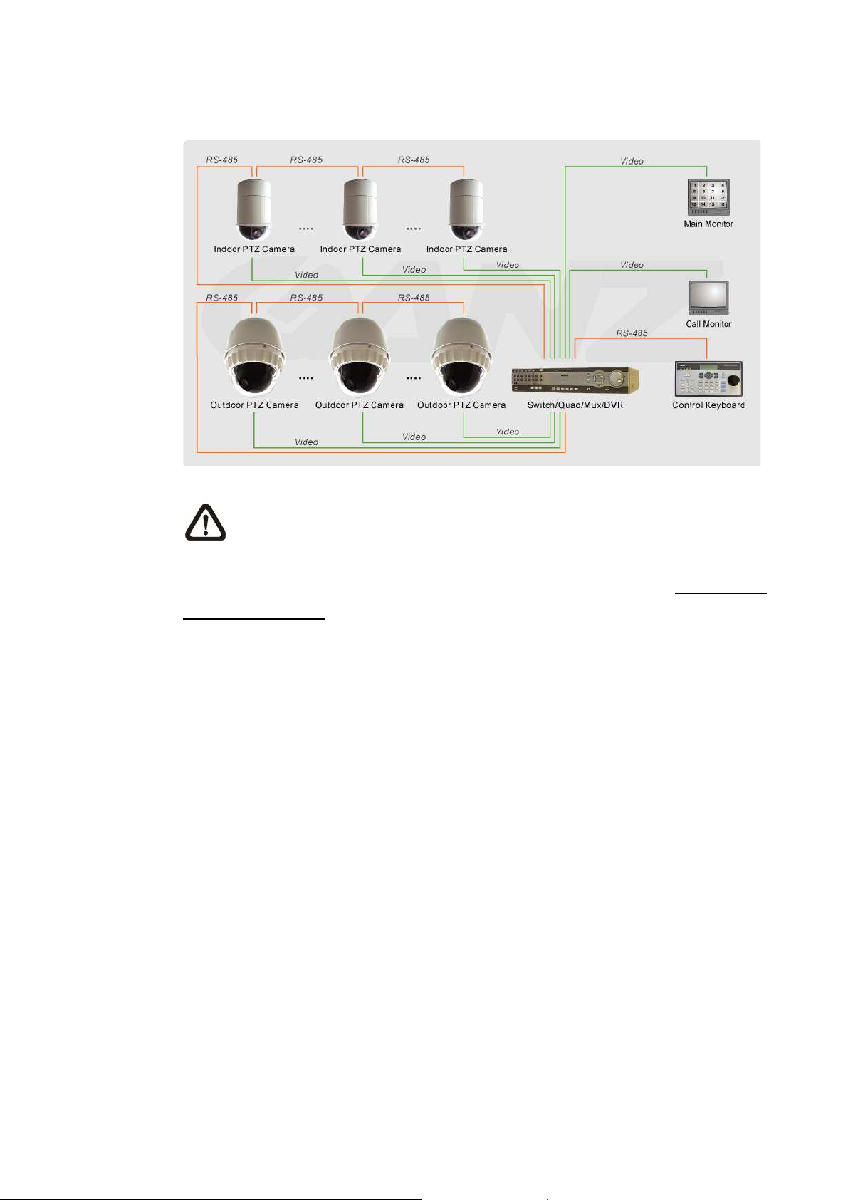
Connect the PTZ Camera to other devices as shown in the diagram to complete a
video surveillance solution.
NOTE: To extend the network distance up to 1.2 km (4000 feet) and to
protect the connected devices, it is highly recommended to place a repeater
at the mid-point. However, a repeater may be needed in the network distance less
than 1.2 km if the used cables are not the CAT 5, 24-gauge cables (see 3.4.4 RS-485
Connector Definition). Refer to the repeater user manual for detailed information.
9
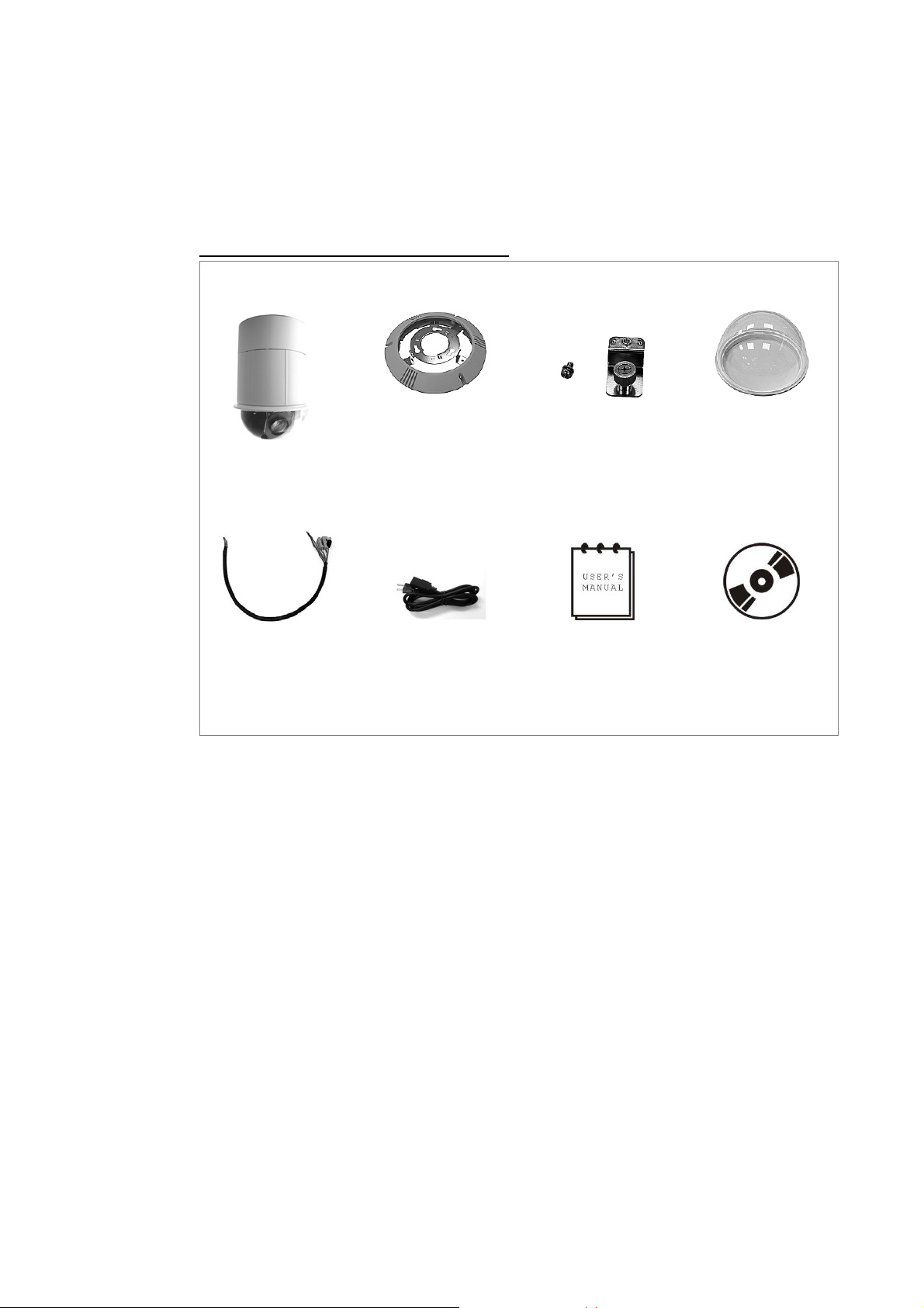
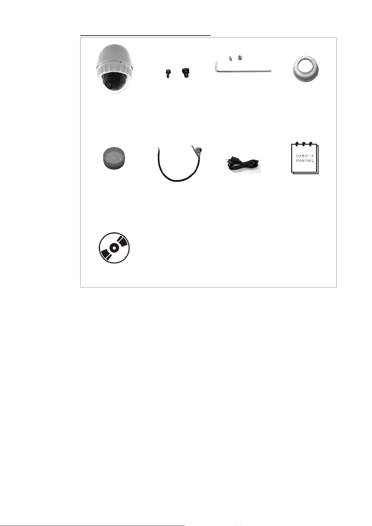
2. Package Content
Before proceeding, please check the box contains the items listed here. If any item is
missing, or if damage is evident, DO NOT install or operate the product and contact
your dealer for assistance.
Indoor PTZ Camera Standard Package
Installation Guide
Camera Body
Cable for Power,
Video, RS-485
and Alarm
Hard Ceiling Mount
and Decoration Ring
Fixing Plate
Power Cord
Installation Guide
& Quick Guide
Optical Cover
CD
10
Installation Guide
Outdoor PTZ Camera Standard Package
Camera Body with
Outdoor Mount Kit
Lubricant
Screws
Cable for Power,
Video, RS-485
and Alarm
Security screw
Power Cord
set
Water-proof rubber
Installation Guide
& Quick Guide
CD
11
Installation Guide
3. PTZ Camera Setups and Cable Connections
Before installing or connecting the PTZ Camera, please refer to this section and
complete preparations for camera setups and various switch setting.
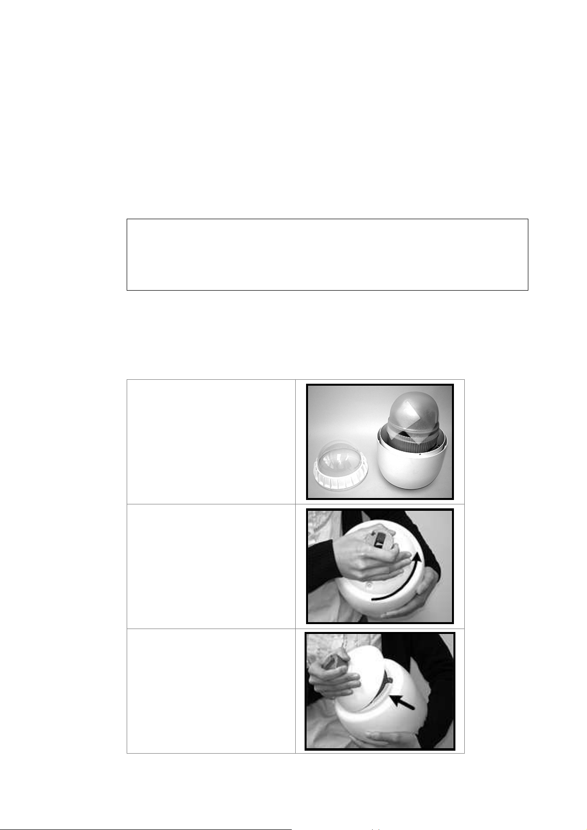
3.1 Preparations for PTZ Camera Setups (Indoor Camera)
There will be a PE cloth sheet covered inside the camera cover and a lens cap on
the lens for shipping protection. Follow the steps below to remove those protective
materials.
Step 1: Unpack the PTZ Camera’s package and take out the camera body.
Step 2: Rotate the dome cover.
Step 3: Remove the PE cloth sheet and take off the lens cap.
Step 4: Replace the dome cover back.
3.2 Preparations for PTZ Camera Setups (Outdoor Camera)
This installation procedure is for the outdoor camera equipped with sunshield
housing. Please follow the steps below to complete camera housing installation.
STEP 1
Unpack the standard camera
package and take out the
camera.
STEP 2
Rotate the Outdoor Mount Kit,
and take it off from the camera
body.
12
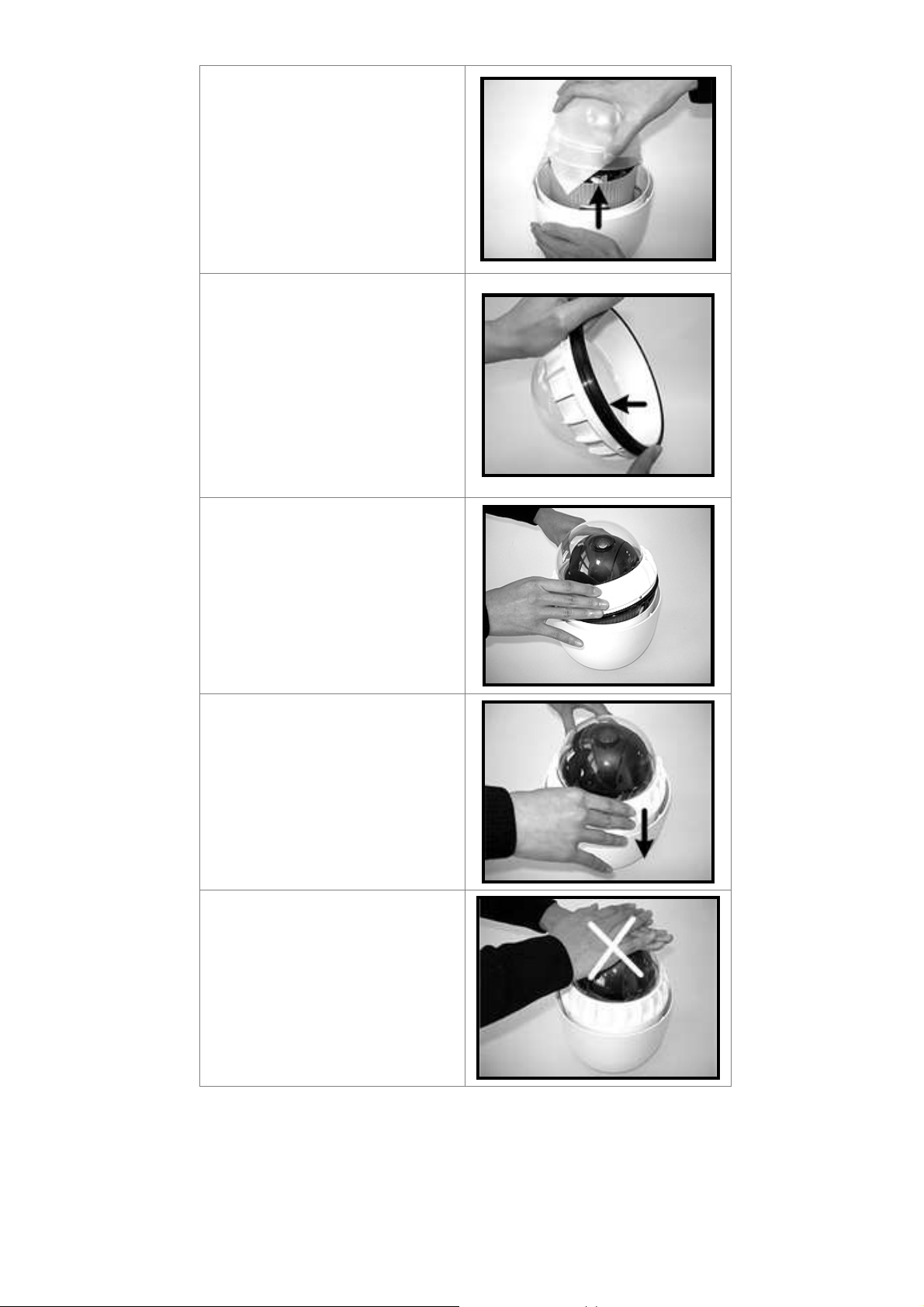
Installation Guide
STEP 3
Remove the protective cover and
PE cloth.
STEP 4
Attach the camera cover to the
camera body. Before doing that,
apply some lubricant on the
cover’s water-proof rubber to
make the installation process
smoother.
Note that the tiny protrusion on
the camera cover must align with
one of the four holes on the
camera body.
STEP 5
Gently pressure the camera
cover downward with two hands
on the side of it.
DO NOT press the cover as
shown in the figure; this might
cause damage to the camera
body.
13
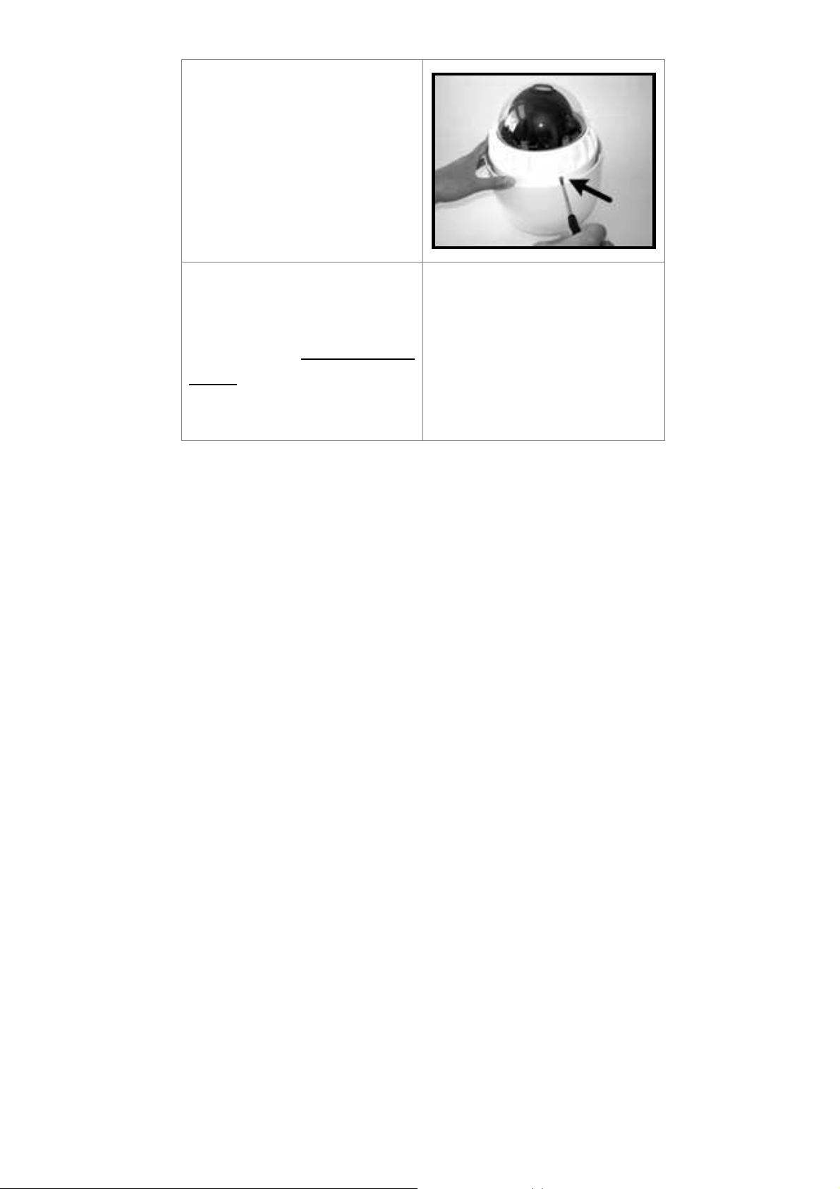
STEP 6
Screw the camera cover and
body together.
Installation Guide
STEP 7
Set the switches located on the
bottom of the camera body.
Refer to section 3.3 PTZ Camera
Setups for detailed information
about various switch setting.
14

Installation Guide
3.3 PTZ Camera Setups
Before connecting the camera to other devices of CCTV system, please complete
the camera ID and communication switch setting. These switches are located on the
bottom of the camera.
3.3.1 Switch Definition
Please refer to the following figures and table for switch location and definitions.
Indoor PTZ Camera Outdoor PTZ Camera
Camera Control Protocol Switch
A
Communication Switch
B
None
C
22-Pin Connector
D
ID Switch
E
Reserved
F
ISP Connector (for FW upgrade)
G
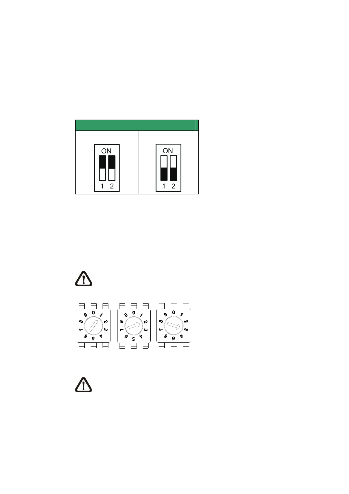
3.3.2 Communication Switch Setting
The table below shows the function of each switch within the Communication Switch.
Communication Switch SW 1
SW 2
RS-485 Setting
SW 3
SW 4
SW 5
SW 6
Termination
Line Lock
Factory Default Reset
Reserved
15
Installation Guide
RS-485 is the interface that communicates the PTZ Camera and its control device;
for this reason, the RS-485 setup of the PTZ Camera and the control device must be
the same. The RS-485 default setting is half-duplex (see the diagram follows).
Please do not change the default setting without qualified specialist or supplier’s
notice. As for the SW 3 and SW 4, they are used for termination and Line Lock
adjustment respectively. The SW 5 is mainly used when users want to restore the
PTZ Camera to the factory default status; moreover, once firmware upgrade is
carried out, users also need to reset the SW 5 afterward.
RS-485 Setting
Half-duplex
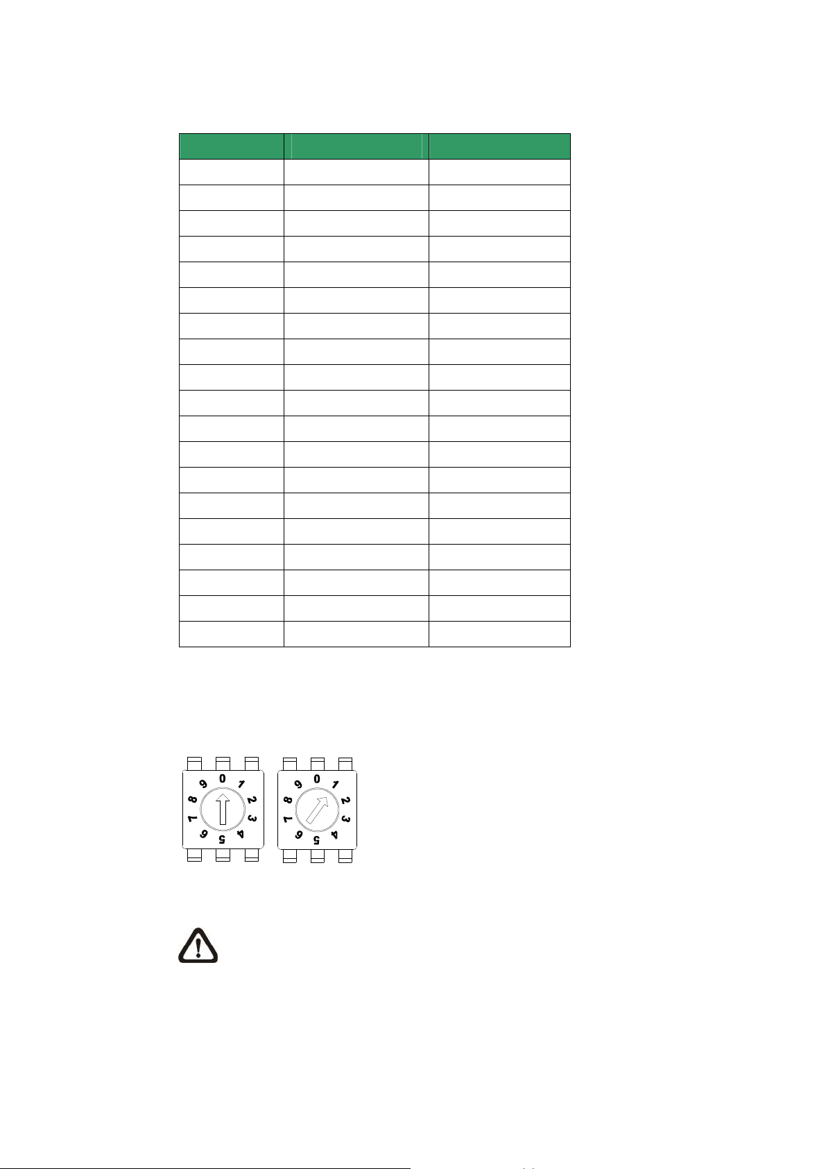
3.3.3 PTZ Camera ID Setting
Please change the camera ID if there is more than one camera on the same
installation site. To change your camera ID, please turn the arrow of the ID switch to
a desired number respectively. For instance, if the camera ID is 123, the ID switch
should be set as below. The default camera ID is “001”.
NOTE: No two cameras should be given the same ID, or communication
conflict may occur.
Full-duplex
Hundreds Tens Units
NOTE: The number “0” should locate upwards as shown in above diagram
for correct switch definition.
3.3.4 PTZ Camera Control Protocol
Protocol is a specific set of rules, procedures used for data communications. Basing
on the devices of your surveillance system and define the protocol you are going to
use. Generally, use one protocol even the devices are provided from different
manufacturers. Use the switch to set your PTZ Camera control protocol and the
16
Installation Guide
baud rate. Refer to below table and turn the arrow to choose a protocol for your
camera.
Switch No. Protocol Baud Rate
00
01
02
04
05
07
08
09
11
12
13
14
15
16
17
18
VCL 9600
Pelco D 2400
Pelco P 4800
Chiper 9600
Philips 9600
GANZ-PT 9600
AD422 4800
DM P 9600
Pelco D 4800
Pelco D 9600
Pelco P 2400
Pelco P 9600
JVC 9600
GANZ-S 4800
GANZ-S 9600
GANZ-S 19200
19
21
22
GANZ-S 38400
Kalatel-485 9600
Kalatel-422 4800
Select protocol: Pelco D with Baud rate 2400, for instance, the protocol switch should
be set as below.
Tens Units
NOTE: The number “0” should locate upwards as shown in above diagram
for correct switch definition.
17
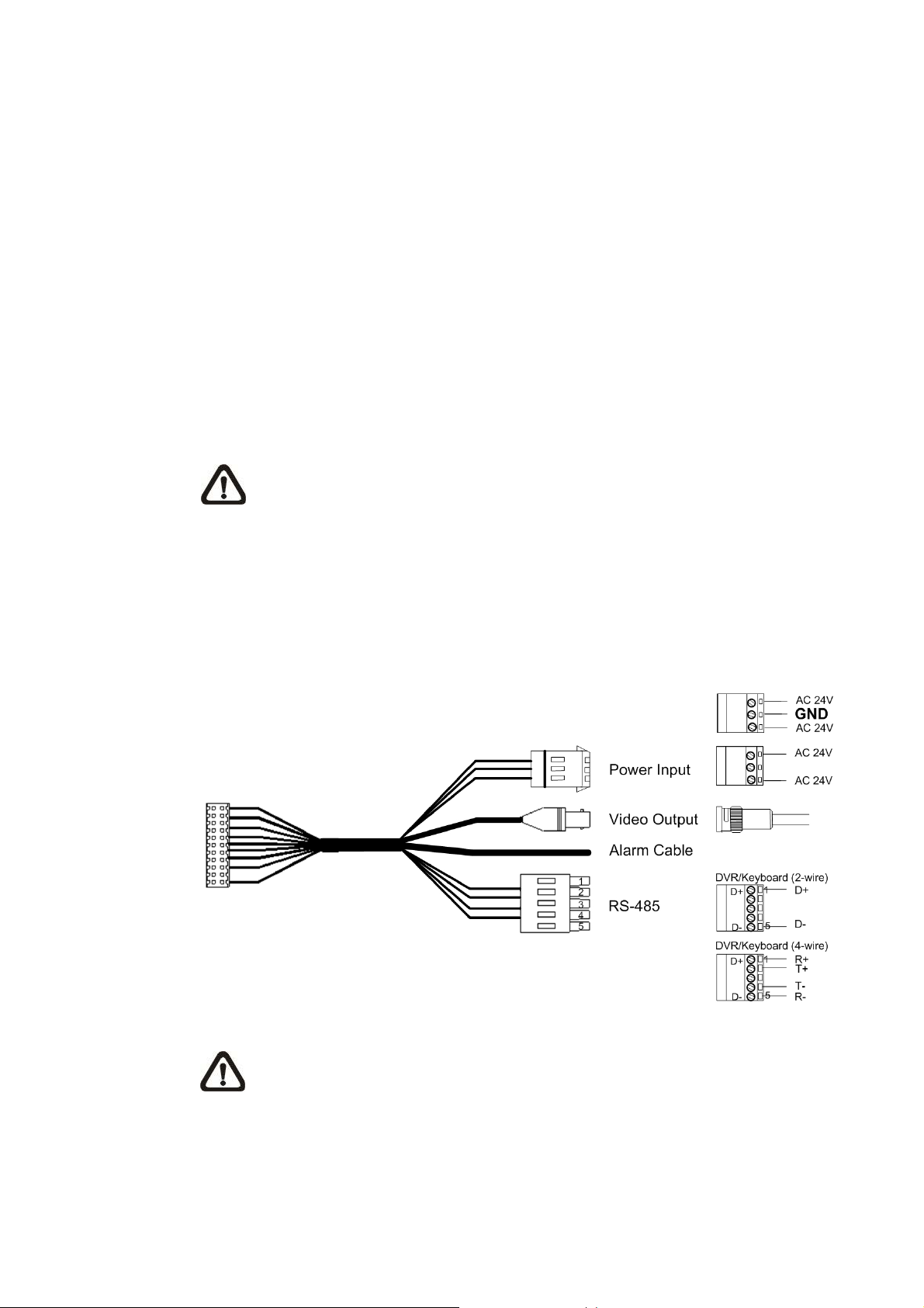
3.4 Cables and Connections
The PTZ Camera is supplied with one integrated 22-pin Data Cable for connecting
with the power, video, and RS-485/audio input & audio output cables. Please read
the following sections thoroughly before making connections.
3.4.1 Cable Requirements
For operation, the PTZ Camera requires video, RS-485 and power cables as
described below:
• The video cable sends video signals to a remote viewing site. Using a coaxial
cable to send video signals is recommended.
• RS-485 cable carries commands from a control device to the dome cameras. A
CAT 5, 24 gauge cable is recommended.
• Power supply: AC 24V output voltage
NOTE: Ensure power supply meets the PTZ Camera’s power requirement,
Installation Guide
or product impairment will occur. If any mistake happens, please contact with
a qualified maintenance engineer.
3.4.2 22-Pin Data Cable
A data cable (see the figure below) is shipped with the PTZ Camera for quick
installation for demo or testing usage.
NOTE: If the power lines use three wires, make sure the Ground wire is
inserted into the mid-pin of the terminal block as shown in the figure above.
18
Installation Guide
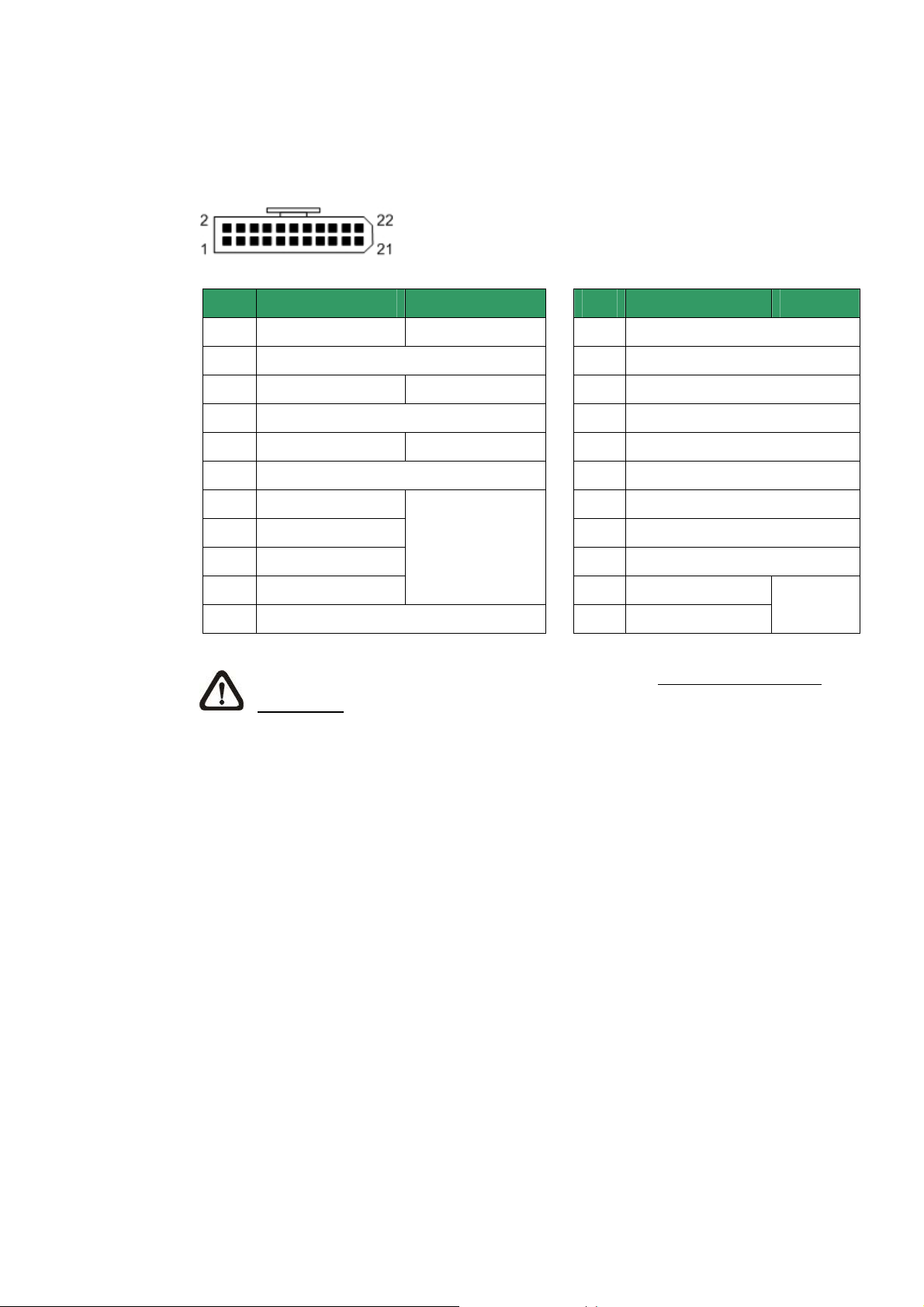
3.4.3 22-Pin Connector Definition
With the 22-pin connector, installers can simply connect the power, video and
RS-485 cables to the camera at once. For the definition of each pin, please refer to
the list below.
Pin
1
2
3
4
5
6
7
8
9
10
11
Definition Cable
AC 24-1
20AWG/18AWG
ALM NC
AC 24-2 20AWG/18AWG
ALM NO
FG 20AWG/18AWG
ALM COM
T+
R-
24AWG
TR+
Alarm ISOG
Pin
12
13
14
15
16
17
18
19
20
21
22
Definition Cable
ALM-1
ALM-3
ALM-2
ALM-4
ALM-5
ALM-6
ALM-7
ALM-8
ALM GND
VGND
Video
20AWG
NOTE: For alarm connection, please refer to section 3.5 Cable Wiring and
Connection.
19

3.4.4 RS-485 Connector Definition
RS-485 is the interface that communicates the camera and its control device. Please
connect the control keyboard to the speed dome through the terminal block. The
recommended cables for RS-485 communication are CAT 5 cables; maximum cable
length for over 24-gauge wire is 4000 feet (1219 meters). If the total cable length
exceeds 4000 feet, using a repeater to maintain the signals is recommended. Please
refer to the figure and table below for pin defination and wiring.
Pin
Corresponding Pins
(22-Pin Connector)
1 7,10 T+, R+ (D+)
2 Reserved
3 Reserved
4 Reservied
5 8,9 T-, R- (D-)
Installation Guide
Definition
20

Installation Guide
3.5 Cable Wiring and Connection
Users may need to conduct cable wiring when: (1) Connecting self-provided cords to
the connector housing (shown in the figure below) instead of using the equipped
data cable or (2) Connecting alarm input and output devices. The table follows will
illustrate the way to wire cords into the connector housing. Please refer to the section
3.4.3 22-Pin Connector Definition for the exact position of each cord.
Insert the terminal into the pin holes
on the connector housing, with the
hook outward, as indicated in the
figure.
To unlock the terminal, press the
hook, as indicated in the figure, with
a proper tool and pull it out gently.
Connect the 22-pin connector to the socket on the PTZ Camera’s back plate.
21
4. PTZ Camera Installation
Basing on different installation environments, both of the Indoor and Outdoor PTZ
Camera can be installed on ceiling, on wall or on pole. In the following sections,
various installation accessories, installation methods and installation procedures will
be described in detail.
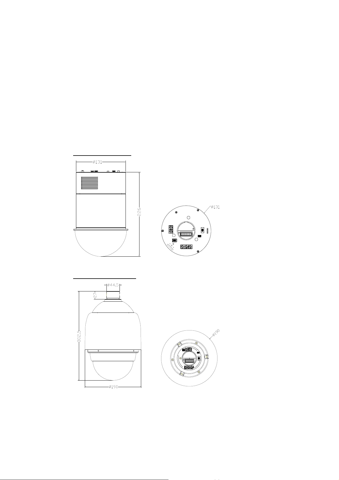
4.1 PTZ Camera Dimension
The indoor PTZ camera’s dimensions are Ø131 x 226 mm (5.2 x 8.9 Inches). The
outdoor camera’s dimensions are Ø172 x 302.5 mm (6.7x11.9 Inches) and Ø190 x
302.5 mm (7.5x11.9 Inches), with sunshield.
Indoor PTZ Camera
Installation Guide
Outdoor PTZ Camera
22

Installation Guide
4.2 Optional Accessories
Indoor PTZ Camera Accessories
Transparent Cover/Smoke Cover (ZCA-CB-5.4/SB-5.4)
Diameter: 137 mm (5.4 inches)
5.4’’ Transparent Cover 5.4’’ Smoke Cover
Power Adapter
ZCA-100-1.5A Input: 100~115VAC/Output: 24VAC 36VA
ZCA-220-1.5A Input: 220~230VAC/Output: 24VAC 36VA
NOTE: When wiring, make sure the G/Y wire (Ground) inserted into the mid-pin
of the terminal block.
Outdoor PTZ Camera Accessories
Sunshield (ZCA-SSH) *equipped with Outdoor Camera
White, Height: 129.5 mm (5.05 inches); Diameter: 190 mm (7.48 inches); 0.15 kg (0.33
lbs)
Vandal Proof (Transparent)/PMMA(Transparent)/Smoke Cover
(ZCA-VP-XT/CB-XT/SB-XT) Diameter: 147 mm (5.8 inches)
Security Screw Set (for Vandal Proof Cover)
23
 Loading...