

Page 1
H.264 NETWORK CAMERA
VCA Interface Manual
Page 2

Page 3

Table of Contents
Introduction ............................................................................................................................... 1
Getting Started .......................................................................................................................... 3
VCA Feature Packages ............................................................................................................... 5
Accessing VCA Configuration ..................................................................................................... 7
Activation................................................................................................................................... 9
Activation............................................................................................................................... 9
Obtaining an Activation Code ................................................................................................ 9
Applying an Activation Code to a Unit ................................................................................ 10
Enabling VCA ........................................................................................................................... 13
Switching VCA On and Off ................................................................................................... 13
Enable VCA ...................................................................................................................... 13
Object Tracking ................................................................................................................ 13
Abandoned/Removed Object Detection ......................................................................... 15
Counting Line ................................................................................................................... 16
Smoke & Fire Detection ................................................................................................... 16
Camera Shake Cancellation ............................................................................................. 16
Enabling Metadata Streaming ............................................................................................. 16
Configuration of Zones and Rules ........................................................................................... 19
Configuration of Zones and Rules ....................................................................................... 19
Tracking Display ............................................................................................................... 19
Properties Inspector ........................................................................................................ 19
Event History ................................................................................................................... 20
Customizing the Tracking Display ........................................................................................ 20
Display Blobs .................................................................................................................... 20
Display Objects in Multiple Colors ................................................................................... 20
Display Non-Alarmed Objects.......................................................................................... 21
Display Object Height ...................................................................................................... 21
Display Object Speed ....................................................................................................... 21
Display Object Area ......................................................................................................... 21
Display Object Classification ............................................................................................ 21
Display Object Wait Time (VCApro only) ......................................................................... 21
Display Object Color Signature (VCApro only) ................................................................ 21
Creating Detection Zones and Lines .................................................................................... 22
Creating a Zone or Line .................................................................................................... 22
Editing Zones and Lines ................................................................................................... 23
Adding and Removing Nodes .......................................................................................... 23
iii
Page 4

Printed Documentation
Non Detection Zones ........................................................................................................... 24
Detection Rules ................................................................................................................... 24
Detection Rules ............................................................................................................... 25
Object Presence ............................................................................................................... 25
Object Direction .............................................................................................................. 26
Object Enter and Exit ....................................................................................................... 26
Object Appear and Disappear ......................................................................................... 27
Object Dwell .................................................................................................................... 28
Object Stopped ................................................................................................................ 29
Object Class ..................................................................................................................... 29
Object Tailgating .............................................................................................................. 30
Abandoned and Removed Object ................................................................................... 32
Object Speed ................................................................................................................... 35
Counting Line ................................................................................................................... 35
Smoke Detection ............................................................................................................. 40
Fire Detection .................................................................................................................. 41
Object Colour Filter ......................................................................................................... 43
Counters .................................................................................................................................. 45
Counters .............................................................................................................................. 45
Creating Counters ................................................................................................................ 45
Assigning Rules to Counters ................................................................................................ 45
Incremental Counters ...................................................................................................... 46
Decremental Counters .................................................................................................... 46
Occupancy Counters ........................................................................................................ 46
Counter Storage and Reporting ............................................................................................... 47
Counter Storage and Reporting ........................................................................................... 47
Database Service ............................................................................................................. 47
Reporting Service............................................................................................................. 47
Database Service ................................................................................................................. 47
Enable Database Service ................................................................................................. 48
DB Storage ....................................................................................................................... 48
Total DB Size .................................................................................................................... 48
Database Table Configuration ......................................................................................... 48
Database Management ................................................................................................... 49
Reporting Service ................................................................................................................ 49
Tabular Reporting ............................................................................................................ 50
Bar Graph Reporting ........................................................................................................ 51
CSV Export ....................................................................................................................... 52
iv
Page 5

Table of Contents
Predefined Requests ....................................................................................................... 53
Command Request .......................................................................................................... 54
Importing Data into Microsoft Excel ................................................................................... 55
Camera Calibration .................................................................................................................. 59
Camera Calibration .............................................................................................................. 59
Camera Calibration Topics ............................................................................................... 59
Calibration Page Elements ................................................................................................... 59
3D Graphics Overlay ........................................................................................................ 59
Mouse controls ................................................................................................................ 59
Other Graphical Tools ...................................................................................................... 60
Calibrating a Camera ........................................................................................................... 62
Step 1: Find some people in the scene ............................................................................ 62
Step 2: Adjust tilt angle and camera height .................................................................... 63
Step 3: Verify the setup ................................................................................................... 63
Tip: If it all goes wrong .................................................................................................... 64
Advanced Calibration Parameters ....................................................................................... 64
Vertical Field of View ........................................................................................................... 65
Measurement Units ............................................................................................................. 65
Object Classification ................................................................................................................ 67
Object Classification ............................................................................................................ 67
Tamper Detection .................................................................................................................... 69
Tamper Detection ................................................................................................................ 69
Advanced Tamper Detection Settings ............................................................................. 69
Scene Change Detection .......................................................................................................... 71
Scene Change Detection ...................................................................................................... 71
Manual Scene Change Detection Settings ....................................................................... 71
Burnt-in Annotation ................................................................................................................ 73
Burnt-in Annotation ............................................................................................................ 73
Object Configuration ....................................................................................................... 73
Counter Configuration ..................................................................................................... 74
System Configuration ...................................................................................................... 74
PTZ Configuration and AutoTracking ....................................................................................... 77
PTZ General Configuration .................................................................................................. 77
Camera Preset Number for VCA Home Position ............................................................. 77
Enable VCA Only at Home Position ................................................................................. 77
Return to Home Position Following Manual Override .................................................... 78
PTZ Auto-tracking Configuration ......................................................................................... 78
Maximum Tracking Time ................................................................................................. 79
v
Page 6

Printed Documentation
Maximum Hold-on Time .................................................................................................. 79
Allow Manual Override (User Control) ............................................................................ 79
Auto-tracking Initiation ................................................................................................... 79
PTZ Profile Configuration .................................................................................................... 80
PTZ Profile Configuration................................................................................................. 80
Creating a New PTZ Profile .............................................................................................. 80
Editing an Existing PTZ Profile ......................................................................................... 81
Removing a PTZ Profile .................................................................................................... 86
Auto-calibrating a PTZ Profile .......................................................................................... 86
Stabilizer .................................................................................................................................. 89
Stabilizer .............................................................................................................................. 89
Stabilizer Configuration ................................................................................................... 89
Border In-fill ..................................................................................................................... 89
Camera Installation Mode ............................................................................................... 90
Auto Disable .................................................................................................................... 90
Performance .................................................................................................................... 91
Maximum Frame Shift ..................................................................................................... 91
Generating External Event Notifications ................................................................................. 93
Load and Save VCA Settings .................................................................................................... 95
Saving VCA Settings ............................................................................................................. 95
Loading VCA Settings ........................................................................................................... 95
Advanced VCA Settings............................................................................................................ 97
Alarm Holdoff Time ............................................................................................................. 98
Measurement Units ........................................................................................................... 100
Metadata Format .............................................................................................................. 100
Event .............................................................................................................................. 100
Object ............................................................................................................................ 100
Counting ........................................................................................................................ 100
Statistics ......................................................................................................................... 101
Do not send empty metadata packets .......................................................................... 101
Blob ................................................................................................................................ 101
Tamper Diagnostics ....................................................................................................... 101
Counting Line Diagnostics ............................................................................................. 101
More Information .......................................................................................................... 101
Stationary Object Hold-on Time ........................................................................................ 101
Tracking Options ................................................................................................................ 102
Minimum Tracked Object Size ....................................................................................... 102
Display Options .................................................................................................................. 102
vi
Page 7

Table of Contents
Minimum Alarm Object Display Time ........................................................................... 102
Minium Object Display Time ......................................................................................... 102
Detection Point of Tracked objects ................................................................................... 102
Restore All Default Settings ............................................................................................... 103
vii
Page 8

Page 9

Introduction
VCAsys is a real-time video analytics engine that utilizes advanced image processing
algorithms to turn video into actionable intelligence. At the core of the product is an
advanced object tracking engine that continually tracks moving and stationary targets. The
tracking engine features built-in robustness to environmental nuisance conditions such as
changing illumination, moving foliage, rippling water, etc.
VCAsys is a generic name for a suite of analytics products that include:
VCApresence: continually tracks moving and stationary targets and generates real-
time alerts of object presence in multiple overlapping detection zones.
VCAsurveillance: continually tracks and classifies moving and stationary targets and
features a full suite of rule-based filters including: enter, exit, appear, disappear,
stopped objects, directionality constraints, object counting, loitering, object type
and object speed. Multiple filters are supported on any combination of multiple
overlapping detection zones.
VCApro: includes all of the features of VCAsurveillance, in addition to an advanced
people tracking engine optimized for tracking people in cluttered indoor scenes such
as retail scenarios. Includes specific high-accuracy counting functions optimized for
use in busy scenes.
A full range of packages: optimized for specific scenarios. See the VCA Feature
Packages topic for detailed information about the packages available for different
platforms.
Using the intuitive web-based configuration application, it's possible to quickly and easily
define rules that generate real-time alerts when triggered. The alerts are available in all
formats supported by the hardware on which it is enabled.
This user guide will help you get VCAsys configured for your application quickly, as well as
lead you through some of the advanced features provided by the product.
Version 2.0.0
1
Page 10

Page 11

Getting Started
In order to get up and running as fast as possible, the following steps should be executed:
Locate a unit that supports VCAsys and ensure it is upgraded to a firmware version
that contains the VCAsys engine.
Obtain an activation code for the feature set required. The different feature levels
available for different platforms are described in the VCA Feature Packages topic.
Connect power, network and input video.
Activate the VCAsys engine.
Calibrate the unit [VCAsurveillance only].
Configure the detection rules.
Configure the alert output format.
3
Page 12

Page 13
VCA Feature Packages
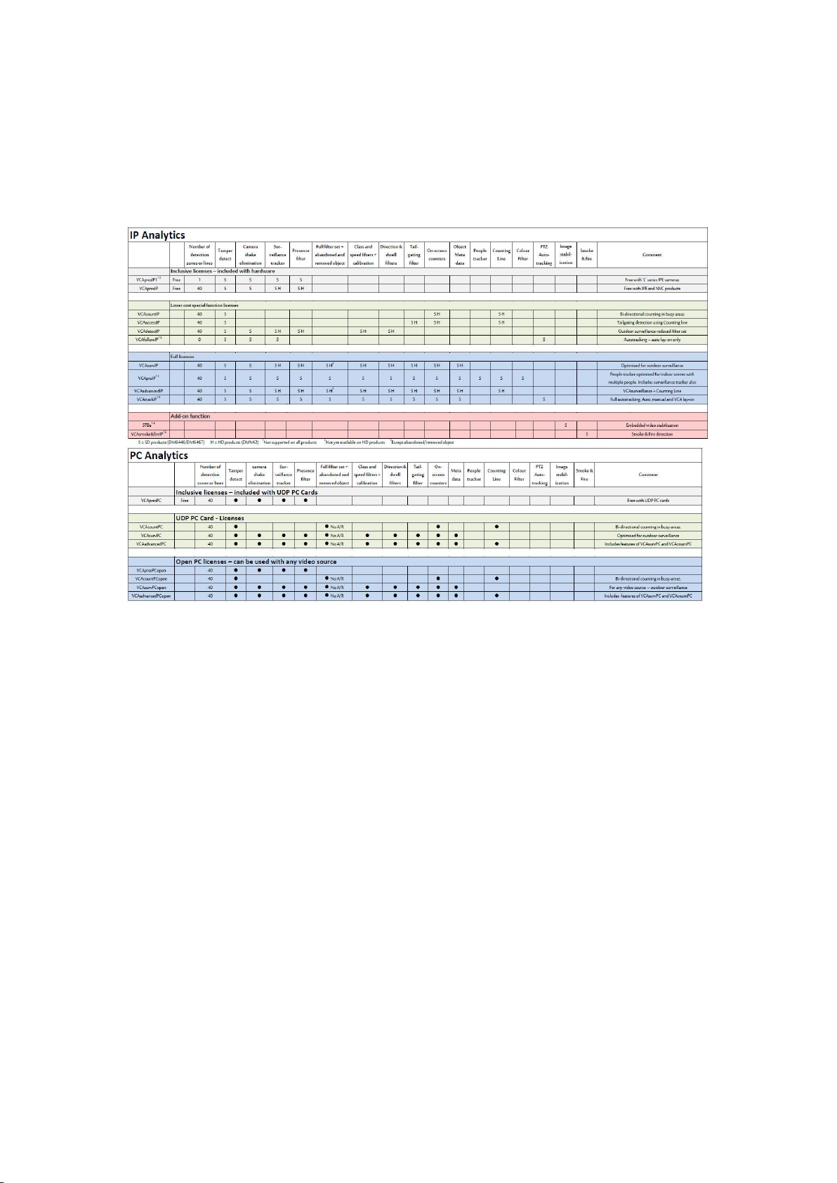
VCA functionality is available in a range of different packages and on different platforms. The
license types available for IP and PC platforms are listed in the following table.
5
Page 14

Page 15
Accessing VCA Configuration
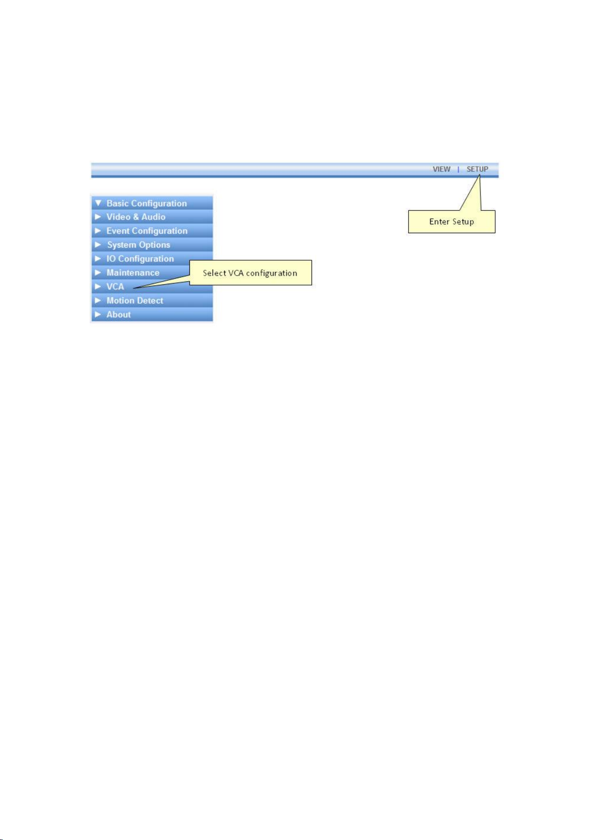
All configuration of the VCAsys engine is performed by accessing the VCA section of the unit
setup page:
7
Page 16

Page 17

Activation
Activation
Some features of VCAsys must be activated before they can be used. Activating VCAsys
consists of the following two steps:
Obtaining an activation code from your hardware supplier.
Applying an Activation code to the unit.
Obtaining an Activation Code
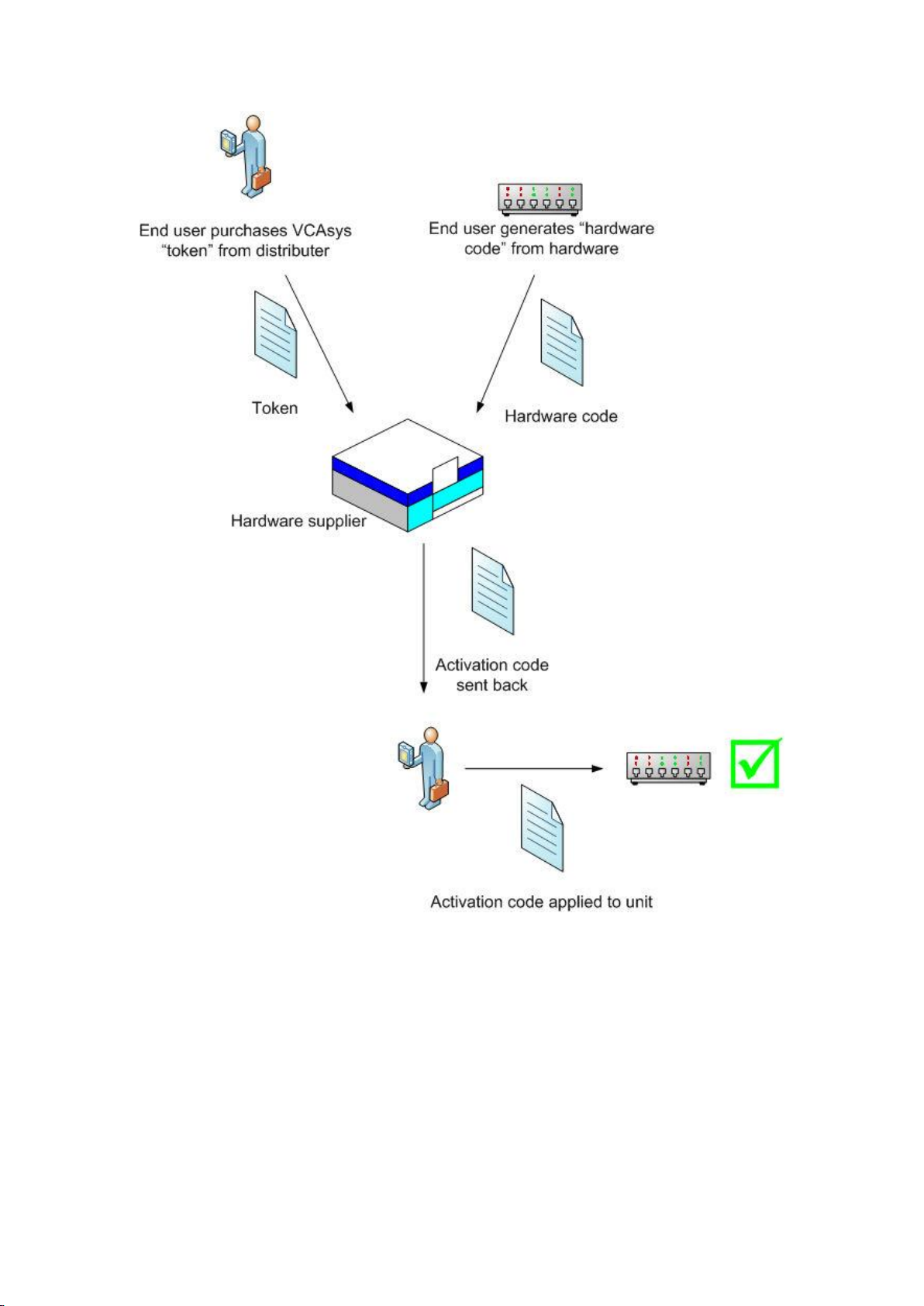
Before VCAsys can be enabled, it must be activated. Typically, an activation code is supplied
by the hardware provider, upon receipt of a valid product token, and a unique hardware ID
generated by the unit on which VCAsys is to be activated.
The activation process is outlined as illustrated:
9
Page 18
Printed Documentation
Applying an Activation Code to a Unit
Once an activation code has been received from your hardware supplier, it's simply a case of
entering the code on the appropriate web page. Select the the Activation menu:
10
Page 19
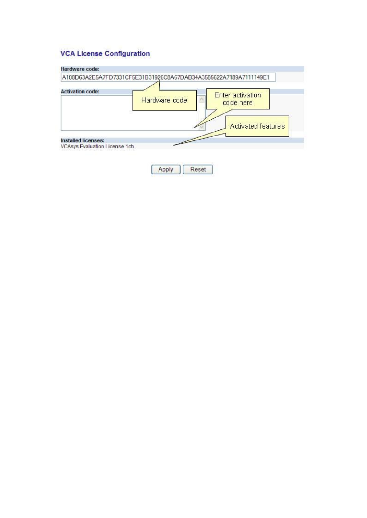
Activation
Enter the activation code and click "Apply". If the activation code is valid, the activated
features will be displayed in the "Installed Licenses" box.
11
Page 20

Page 21
Enabling VCA
Switching VCA On and Off
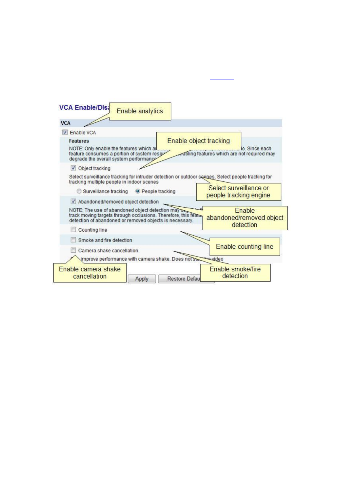
By default, VCA is disabled. In order to enable VCA it must be activated. Select the VCA menu
and then the Enable/Disable sub menu. Tick the Enable check box under Analytics and select
the required mode.
Enable VCA
Check/Uncheck to enable/disable the VCA functionality at a global level. If unchecked, ALL
VCA functionality will be disabled.
Object Tracking
Check/Uncheck to enable/disable the object tracking engine. When checked, there are 2
modes of object tracking available, optimized for different applications:
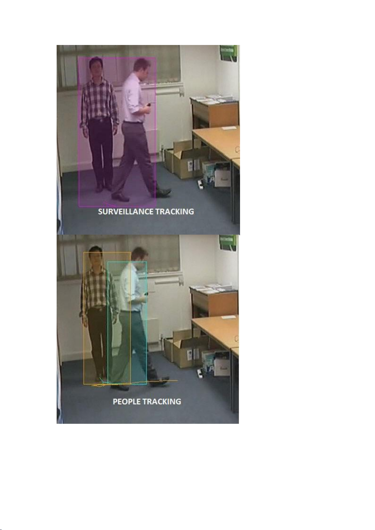
Surveillance Tracking
Optimized for intrusion detection and general purpose outdoor object detection and
tracking. When objects are in close proximity to each other they are more likely to be
tracked as a single object than separate entities. Consumes fewer system resources than the
People Tracking engine.
People Tracking
13
Page 22

Printed Documentation
Optimized for tracking people in indoor cluttered scenes. Exhibits higher performance when
people are in close proximity to each other - people are tracked even when one person is
obscured by the other.
NOTE:
The People Tracking engine consumes more system resources than the Surveillance
Tracking engine. Therefore, the encoded frame rate may be reduced if this mode is
selected.
Best performance is achieved when the camera has been correctly calibrated.
The People Tracking engine requires a VCApro license.
The following illustration highlights the difference in performance between the two modes:
14
Page 23
Enabling VCA
Abandoned/Removed Object Detection
Check/Uncheck to enable/disable abandoned/removed object detection. When checked, a
background process to detect abandoned and removed objects is enabled.
15
Page 24

Printed Documentation
NOTE: The use of abandoned object detection may degrade the ability of the tracking engine
to track moving targets through occlusions. Therefore, this feature should only be enabled if
the detection of abandoned or removed objects is necessary.
Counting Line
Check/Uncheck to enable/disable the counting line functionality. The counting line
functionality requires a VCApro, VCAcount or VCAaccess license.
Smoke & Fire Detection
Check/Uncheck to enable/disable the smoke and fire detection functionality. The smoke &
dire detection functionality requires a VCAsmoke&fire license.
NOTE: The smoke and/or fire detection filter does not comply with any detection
standards and should not be used as a safety device. It should be installed in addition to
certified safety devices and used only to supply additional information.
Camera Shake Cancellation
The camera shake cancellation function is used to improve the VCA performance with
cameras that are prone to shake. By default, camera shake cancellation is disabled. If your
installation suffers from camera shake problems, enable this function to improve the VCA
performance. If camera shake is not an issue in your installation, best performance will be
achieved with this setting disabled.
NOTE: Only enable the features which are necessary for the deployment scenario. Since
each feature consumes a portion of system resources, enabling features which are not
required may degrade the overall system performance.
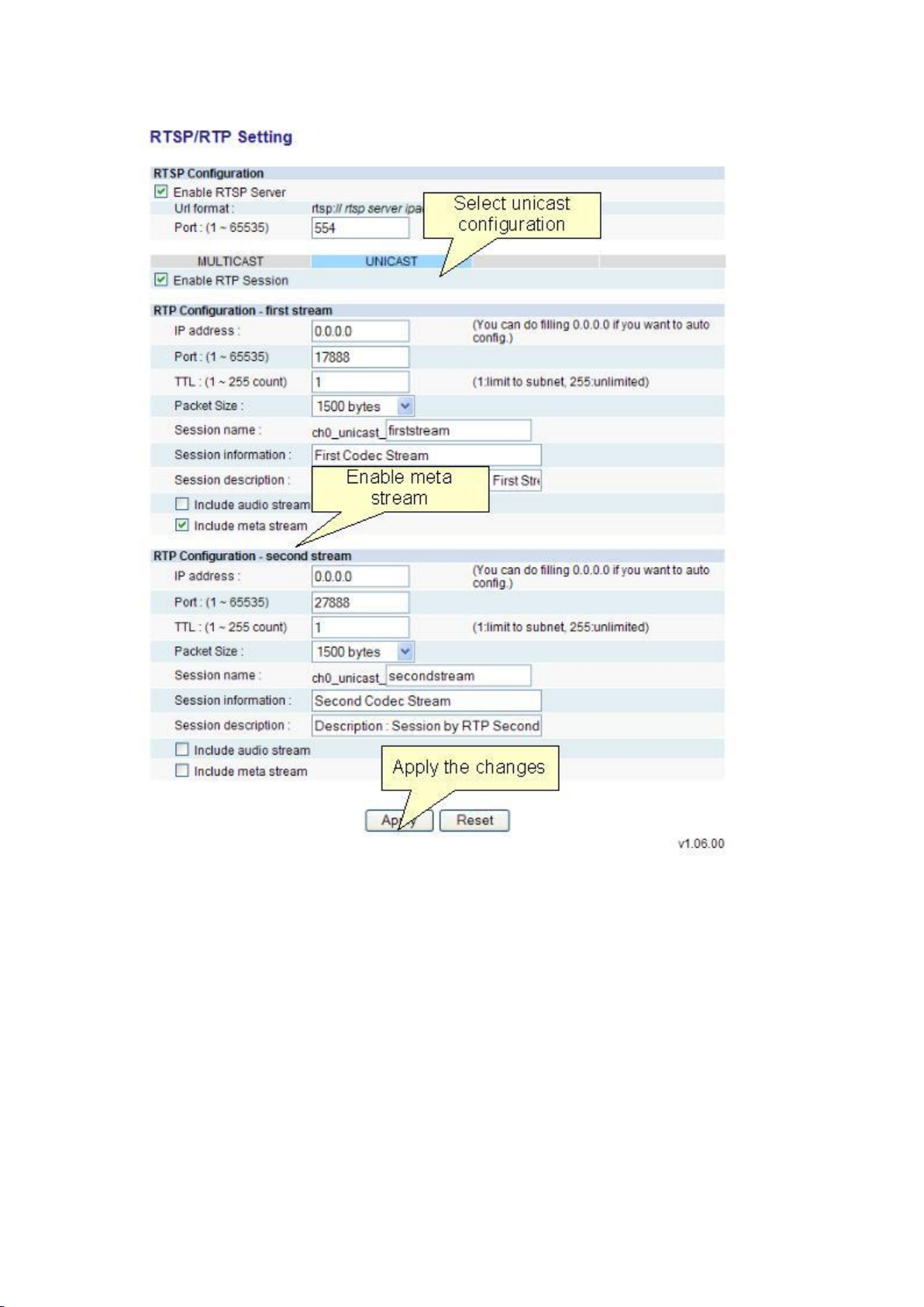
Enabling Metadata Streaming
In order to visualize the VCA output, metadata streaming must be enabled for RTP. Select
System Options and then the RTSP/RTP sub menu:
16
Page 25
Enabling VCA
17
Page 26

Page 27
Configuration of Zones and Rules
Configuration of Zones and Rules
In order to create some useful output, it is necessary to configure detection zones and
detection rules. The detection zones and rules are configured by selecting VCA and then the
Zones and Rules sub menu:
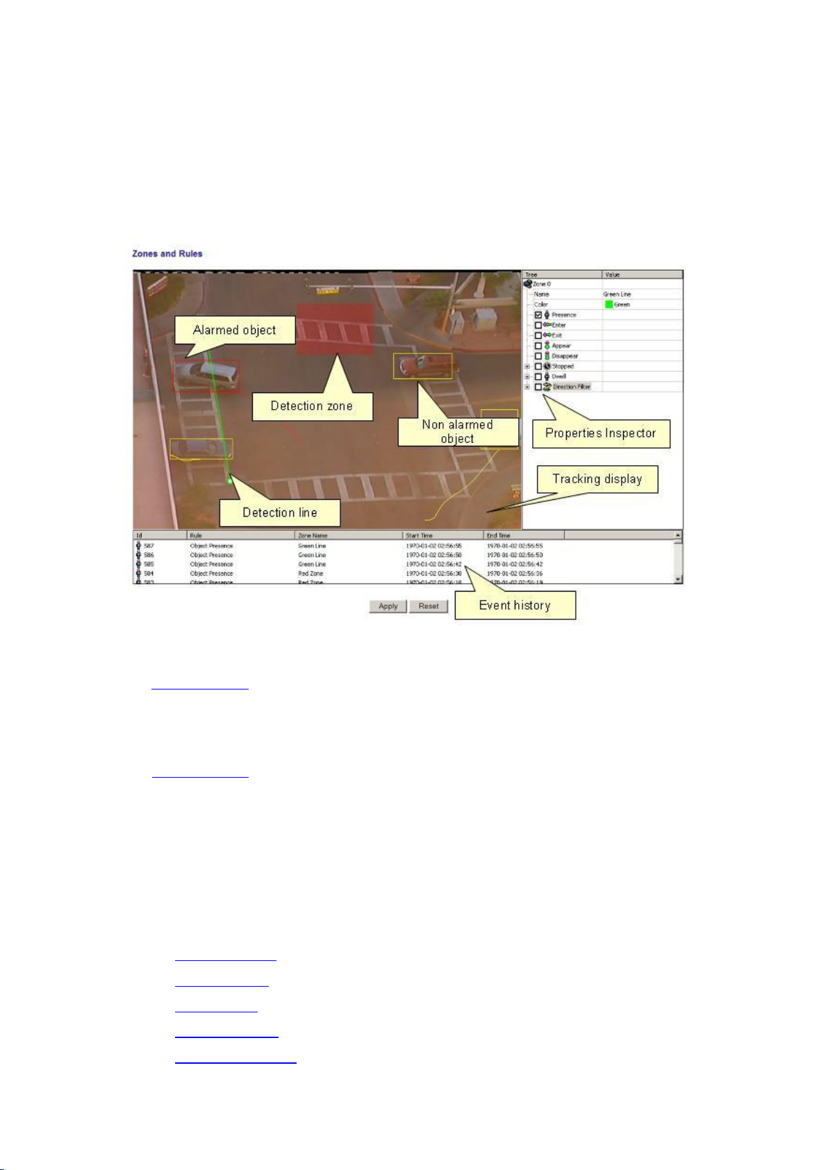
Tracking Display
The tracking display window shows all moving and stationary targets that are currently being
tracked by the engine. Objects that have triggered a rule are displayed in red. Conversely,
objects that have not triggered a rule are displayed in yellow.
This snapshot shows a detection zone, in red and a detection line, in green.
The tracking display window is useful for predicting how the rules will operate. By examining
how the trails of the objects intersect the detection zones and lines, it is possible to
determine how the rule can be optimally configured.
Properties Inspector
The properties inspector allows the user to assign detection rules to detection zones and
detection lines. Available rules will depend on the features available and settings applied,
and may include the following:
Object presence
Object entered
Object exited
Object appeared
Object disappeared
19
Page 28
Printed Documentation
Object stopped
Object dwell
Object direction
Object speed
Object tailgating
Counting line
Abandoned/removed object
Smoke detection
Fire detection
Object colour filer
Event History
The event history control shows the history of objects that have triggered rules and
generated alarms.
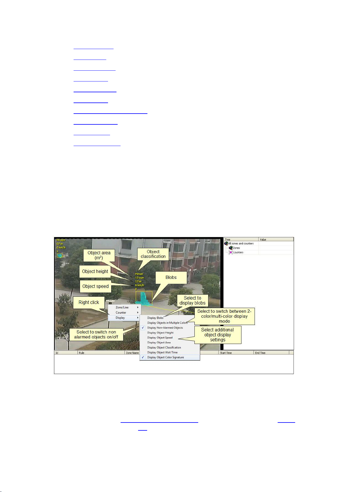
Customizing the Tracking Display
The tracking display window can be customized to show various levels of tracking data.
Simply right click on the tracking display window and select the Display option:
Display Blobs
By default, the blobs are not displayed. It's possible to switch the blob display on in order to
observe how the algorithm performs in different scenarios. Moving blobs are displayed in
blue, as illustrated in the figure. Blobs that correspond to abandoned/removed objects are
displayed in pink. See the Abandoned/Removed objects topic for further information. Smoke
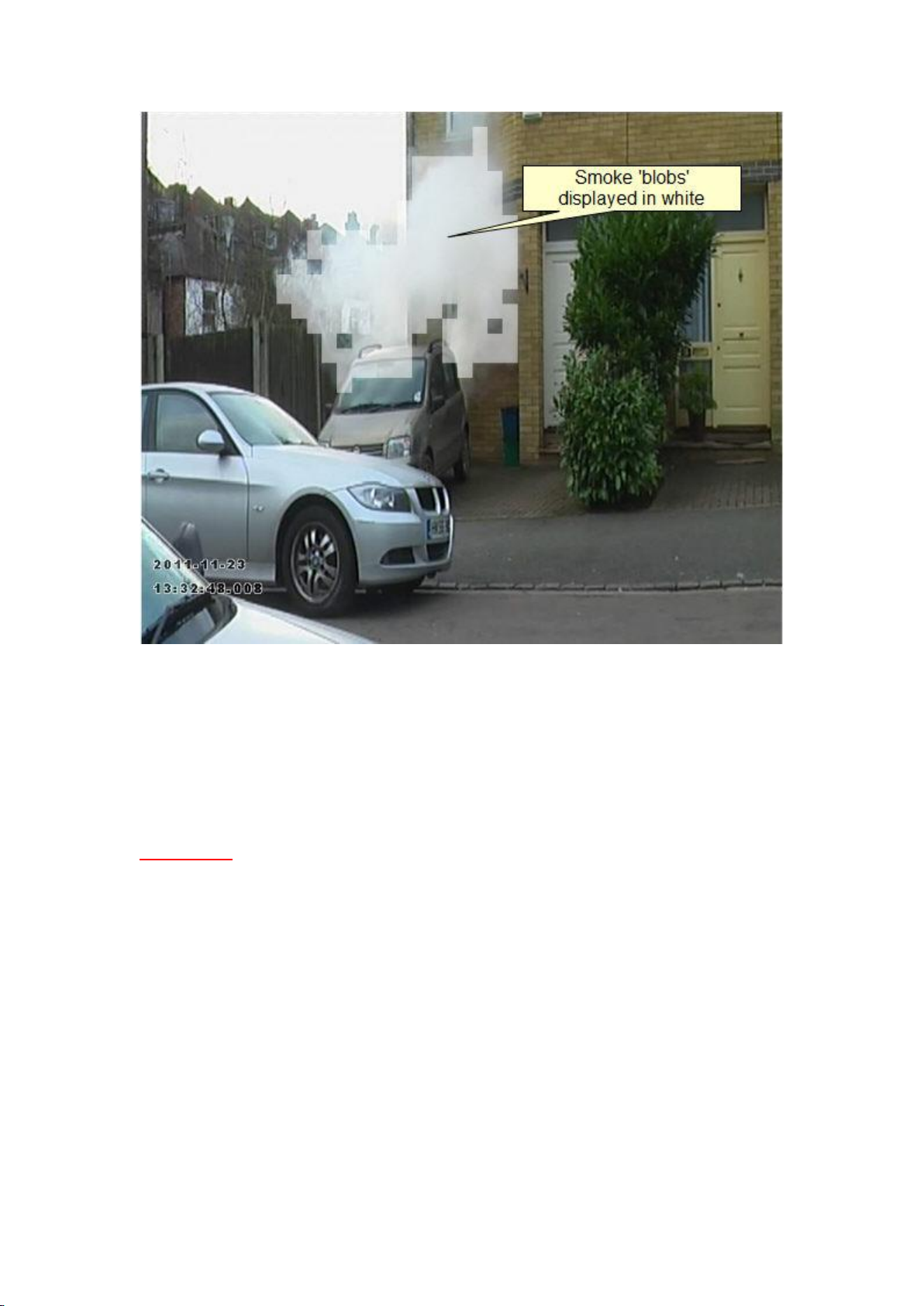
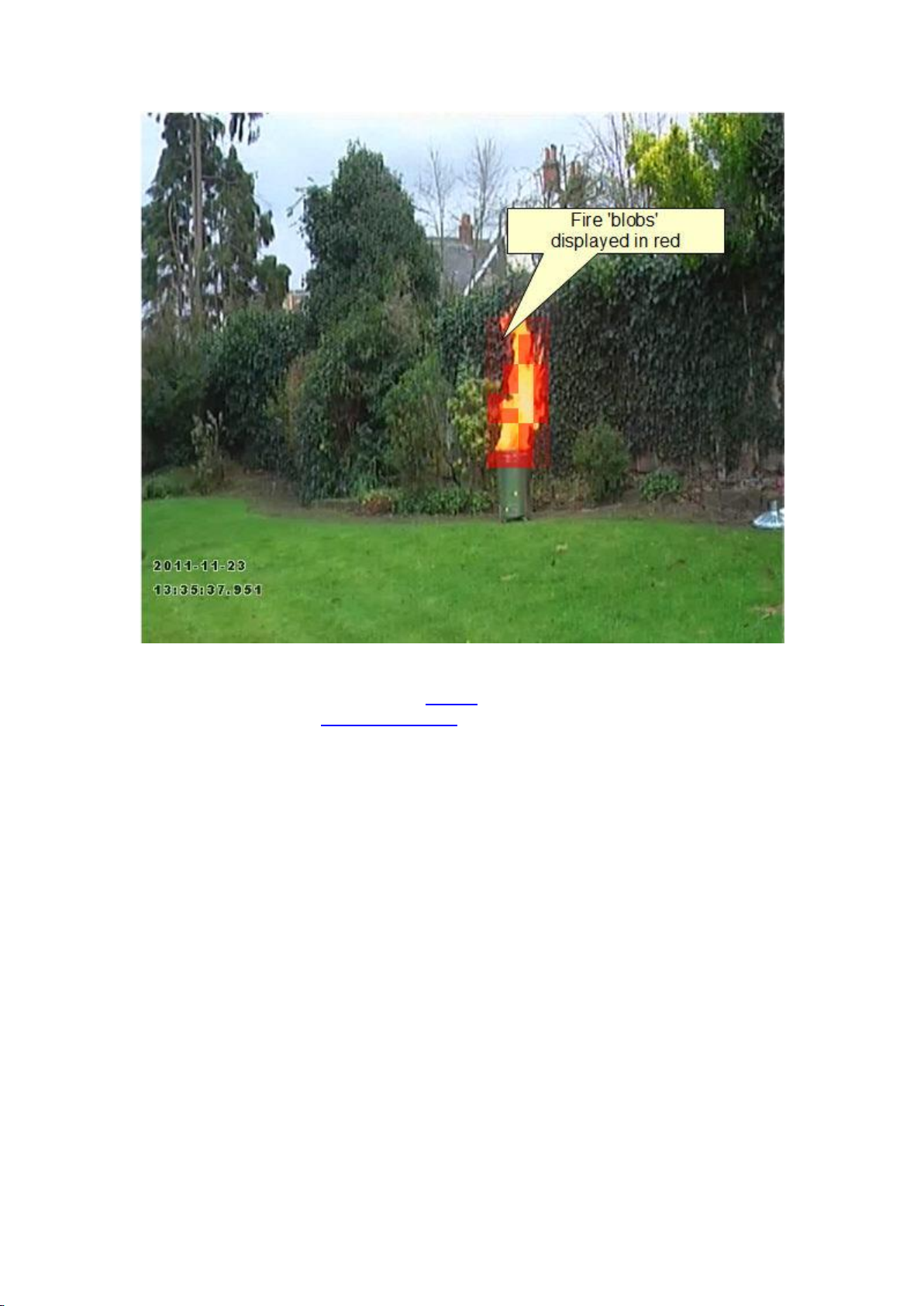
blobs are displayed in white and fire blobs are displayed in red.
Display Objects in Multiple Colors
20
Page 29

Configuration of Zones and Rules
Select this option to toggle between 2-color display mode (alarmed objects in red, nonalarmed objects in yellow), or multi-color displayed mode. In multi-color display mode,
objects are displayed in a color selected by the system.
Display Non-Alarmed Objects
By default, all objects are displayed: alarmed objects in red; and non-alarmed objects in
yellow. The display of non-alarmed objects and their trails helps optimally configure the
rules by allowing the user to see how the detection zones and object trails intersect.
Uncheck this item to switch the display of non-alarmed objects off.
Display Object Height
Check this option to display the object height. This option is only available when the camera
has been calibrated.
Display Object Speed
Check this option to display the object speed. This option is only available when the camera
has been calibrated.
Display Object Area
Check this option to display the object area. This option is only available when the camera
has been calibrated.
Display Object Classification
Check this option to display the object classification. This option is only available when the
camera has been calibrated.
Display Object Wait Time (VCApro only)
Check this option to display the amount of time that the object has spent inside a zone.
Useful for measuring customer dwell times in specific areas of the scene. Note that the
statistics metadata option must be enabled in the Advanced Settings page.
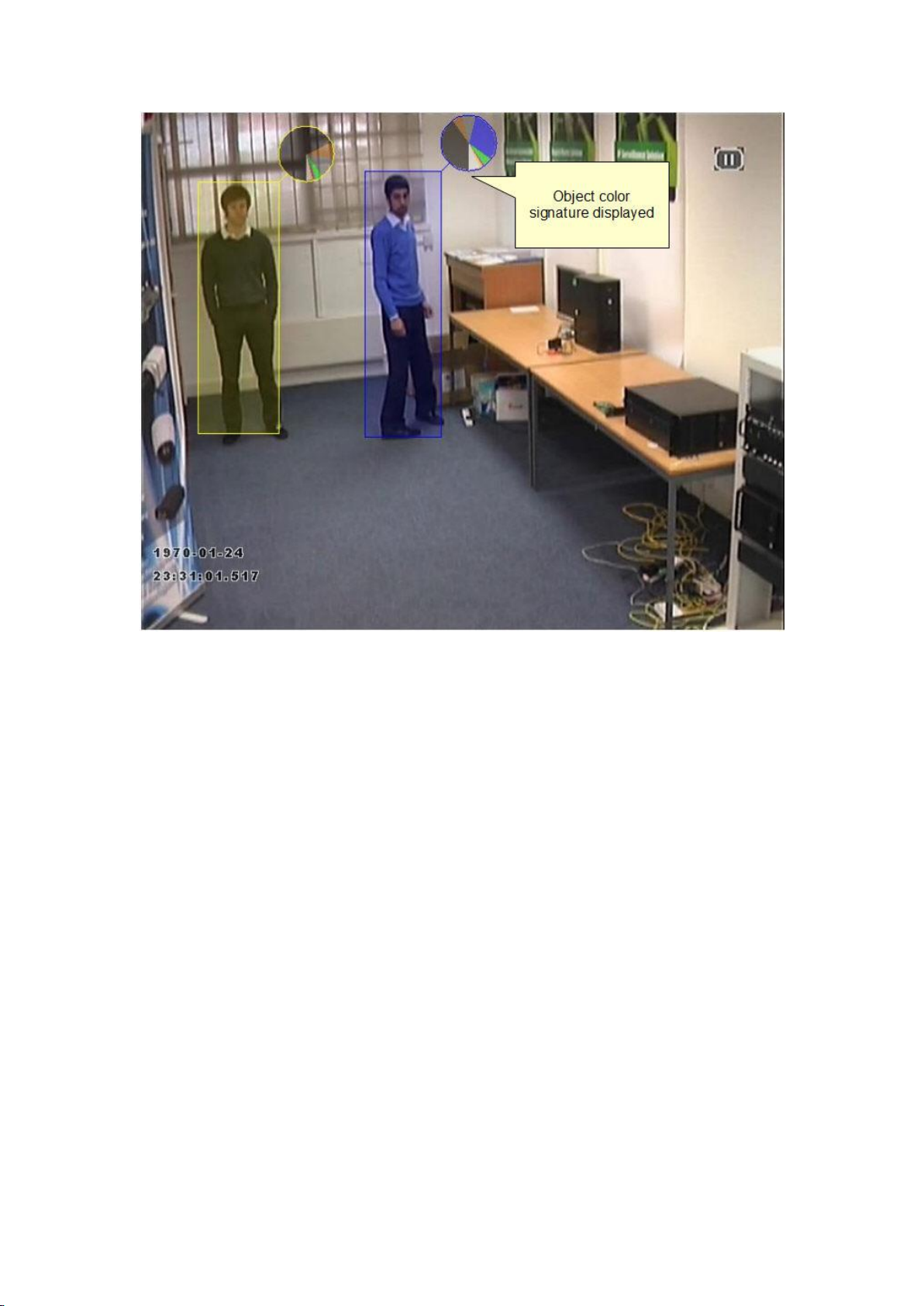
Display Object Color Signature (VCApro only)
Check this option to display the color signature of the object. Note that the color signature
metadata option must be enabled in the Advanced Settings page, and the People Tracking
mode must be selected on the Enable/Disable page.
21
Page 30
Printed Documentation
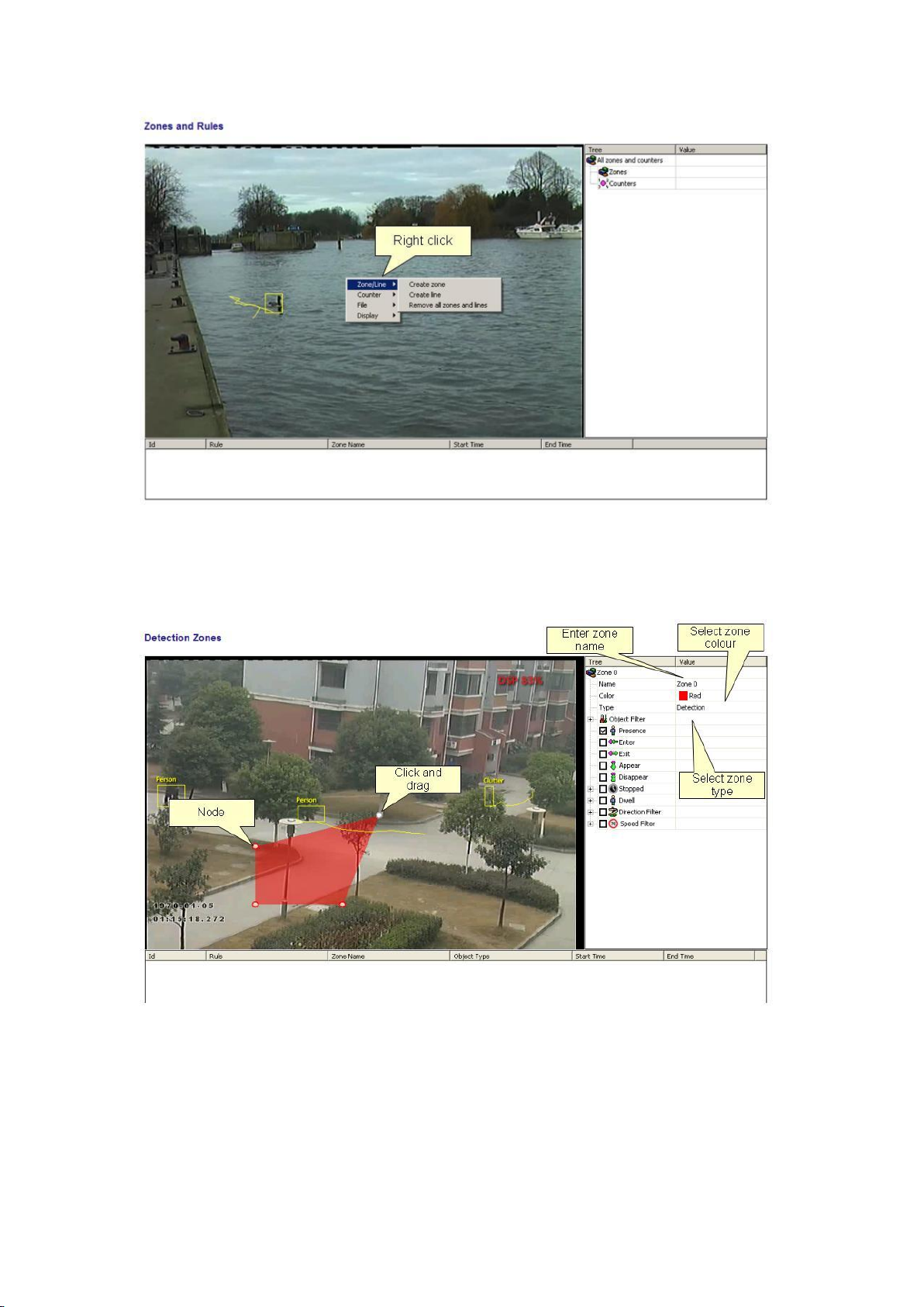
Creating Detection Zones and Lines
In order to detect events of interest, detection zones and lines must be defined. Detection
zones define an area of interest. Detection lines are similar to detection zones but they
define a perimeter instead of a region.
Creating a Zone or Line
To create a zone, either double click the left mouse button or right click and select
Zone/Line... Create zone:
To create a line, right click and select Zone/Line... Create line:
22
Page 31
Configuration of Zones and Rules
Editing Zones and Lines
Zones and lines can be edited to be any shape or size. Zones and lines are controlled by
manipulating "nodes" that represent the zone/line vertices. To change the shape of a zone
or line, simply grab a node with the left mouse button and drag it to the desired location:
Adding and Removing Nodes
Zones and lines can be tailored to any scenario by simply adding more nodes to define the
shape required. To add a node, simply double click on the zone or line at the point where
the new node should be added. Nodes can be deleted by right clicking on the node and
selecting Node... Remove node:
23
Page 32
Printed Documentation
Non Detection Zones
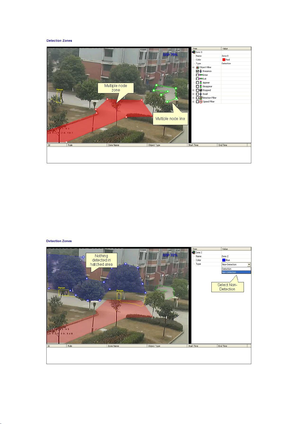
In some situations, especially where the scene is busy, objects tracked in some areas can
interfere with detection zones in other areas. For example, on a windy day, moving foliage
can generate false alarms that in some situations could be tracked through a detection zone.
In order to minimize such issues, it is possible to configure "non-detection" zones, where
nothing is detected or tracked.
Detection Rules
24
Page 33

Configuration of Zones and Rules
Detection Rules
Once some detection zones and/or lines have been configured, it's possible to define some
detection rules that apply to the zones/lines. By default, zones and lines are automatically
configured to detect object presence.
The rules are defined in the Properties Inspector:
The properties inspector is context-sensitive to the zone selected. As different zones/lines
are selected, so the properties inspector changes to reflect the rules currently configured on
that zone. Defining a rule is a simple matter of checking the box next to the rule required. In
all cases, the rules are configured with sensible default values. Of course, these can be
customized to suit the detection scenario. The selection of multiple rules on a detection
zone is supported.
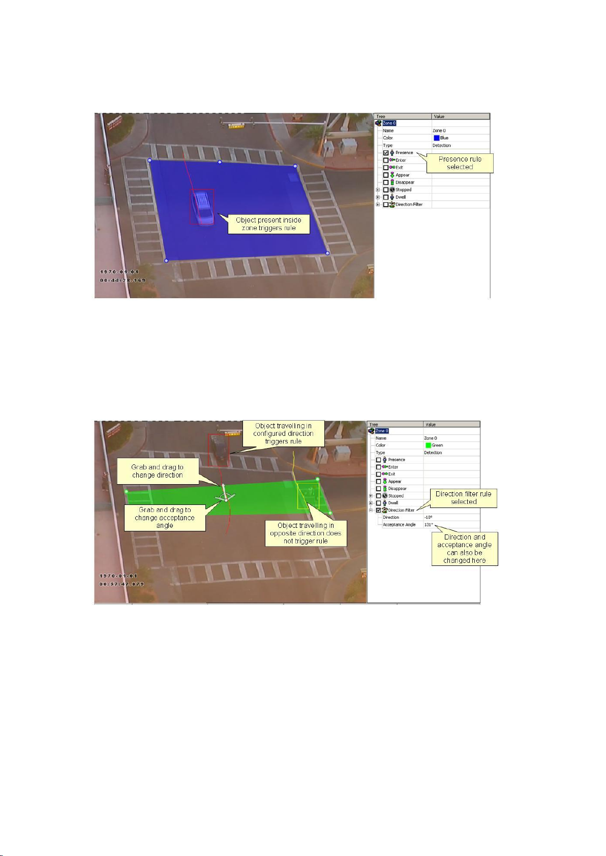
Object Presence
Enable the object presence rule on the selected zone by checking the Presence box in the
properties inspector and click apply.
25
Page 34
Printed Documentation
Objects that are present inside a zone or pass through a line will trigger the rule and raise an
alarm.
Object Direction
Enable the object direction rule on the selected zone by checking the Direction Filter box in
the properties inspector. Adjust the direction and acceptance angle to suit the detection
scenario.
Objects that travel in the configured direction (within the limits of the acceptance angle)
through a zone or over a line trigger the rule and raise an alarm.
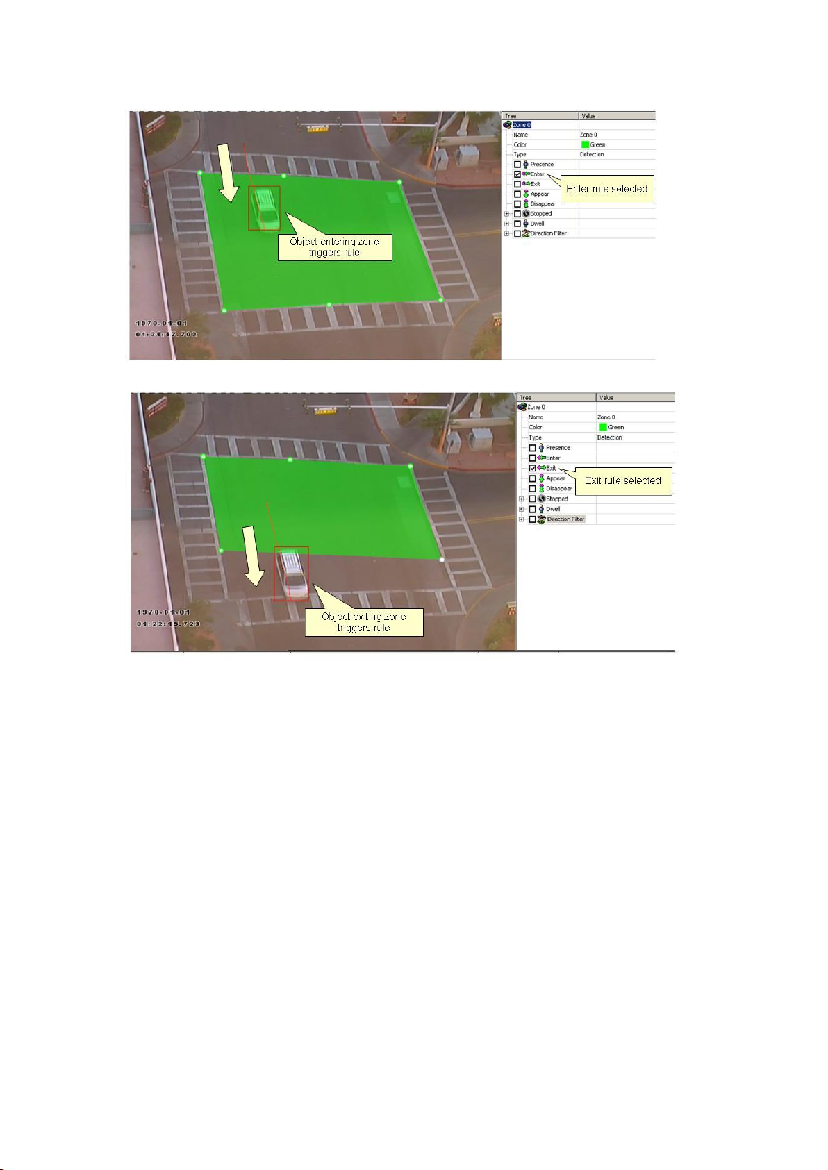
Object Enter and Exit
Enable the object enter and exit detection by checking the corresponding check boxes in the
properties inspector and click apply.
An object entered alarm is raised when an object crosses from the outside to the inside of a
detection zone. Conversely, an object exited alarm is raised when an object crosses from the
inside to the outside of a detection zone:
26
Page 35
Configuration of Zones and Rules
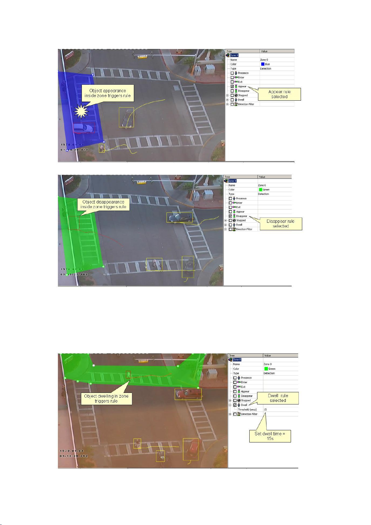
Object Appear and Disappear
Enable the object appear and disappear detection by checking the corresponding check
boxes in the properties inspector and click apply.
An object appear alarm is raised when an object appears inside a detection zone. Note that
this is different from object entered detection since the object must be initially detected
inside the zone without entering, e.g. people appearing in a doorway, or cars appearing from
an underground carpark.
Conversely an object disappear alarm is raised when an object disappears inside a detection
zone. Again, this is different from object exit detection since the object must be tracked into
the zone and then disappear without exiting the zone.
27
Page 36
Printed Documentation
Object Dwell
Enable the object dwell rule on the selected zone by checking the Dwell box in the
properties inspector and click apply.
Objects that dwell inside a zone for longer than the defined amount of time will trigger the
rule and raise an alarm.
28
Page 37
Configuration of Zones and Rules
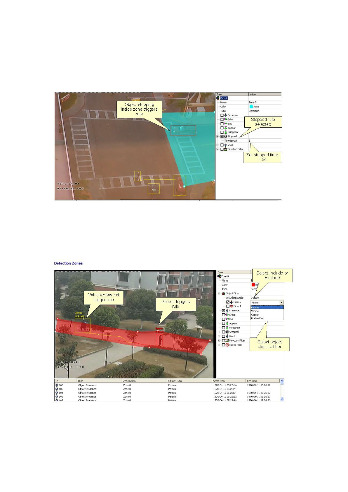
Object Stopped
Enable the object stopped rule on the selected zone by checking the Stopped box in the
properties inspector and click apply.
Objects that are stopped inside a zone for longer than the defined amount of time will
trigger the rule and raise an alarm.
The stopped time can be configured by simply clicking in the Time box on the rule control
and editing the value in-place.
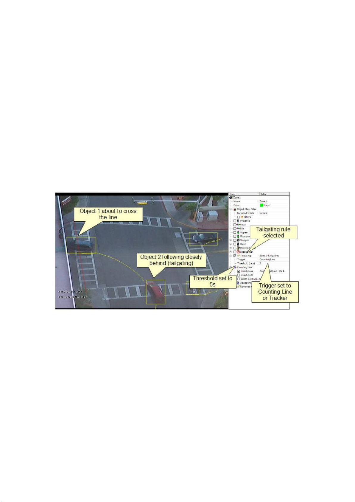
Object Class
Once the camera has been calibrated, it's possible to include or exclude specific object types
in the detection rules.
Select and enable an Object Filter by checking the box. Select whether the rule should
include or exclude the object type. Select the object type to include or exclude.
Apply the changes.
29
Page 38
Printed Documentation
In this example, the rule has been configured to include detection of people only. As
illustrated, the person generates an alarm, but the vehicle is filtered out and does not trigger
the alarm.
Object Tailgating
Enable the object tailgating rule on the selected zone by checking the Object Tailgating box
in the properties inspector. Adjust the time threshold to set the minimum allowable time
between successive object detections.
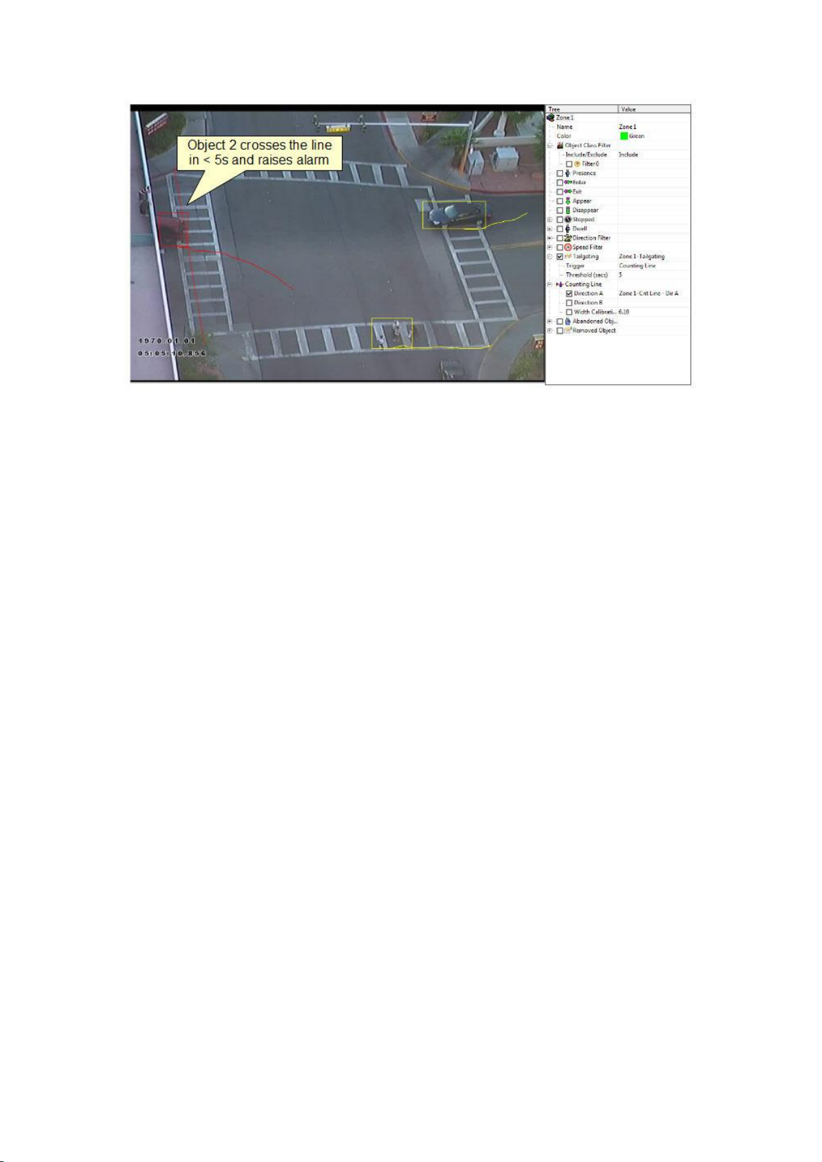
Object tailgating is defined as an object crossing a line or zone within a certain time after an
object has already crossed the line or zone. If an object crosses a line or zone, and another
object crosses the same line or zone within the specified time window, the Object Tailgating
filter will be triggered.
In this example, Object 1 is about to cross a detection line. Another object (Object 2) is
following closely behind. The tailgating detection threshold is set to 5 seconds. That is, any
object crossing the line within 5s of an object having already crossed the line will trigger the
Object Tailgating filter.
Object 2 crosses the line within 5 seconds of Object 1. This triggers the Object Tailgating
filter.
30
Page 39
Configuration of Zones and Rules
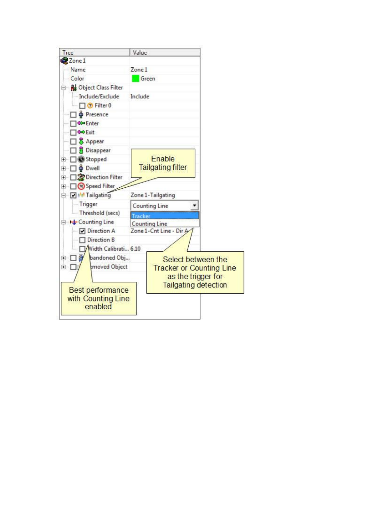
Object Tailgating Trigger
The tailgating filter can use either the tracking engine or the counting line as trigger sources
for tailgating detection. Since the counting line exhibits higher performance when detecting
multiple objects crossing a line, best performance will be obtained when the trigger is set to
"Counting Line". If a counting line filter is already configured on the line, then the trigger is
automatically set to "Counting Line".
Note that a VCApro, VCAaccess or VCAcount license is required to enable the counting line.
31
Page 40
Printed Documentation
Abandoned and Removed Object
VCAsys can be configured to generate an alert highlighting an abandoned or removed object.
Suspicious objects can be detected when carried into the scene and planted by a person as
well as when dropped or thrown into the scene.
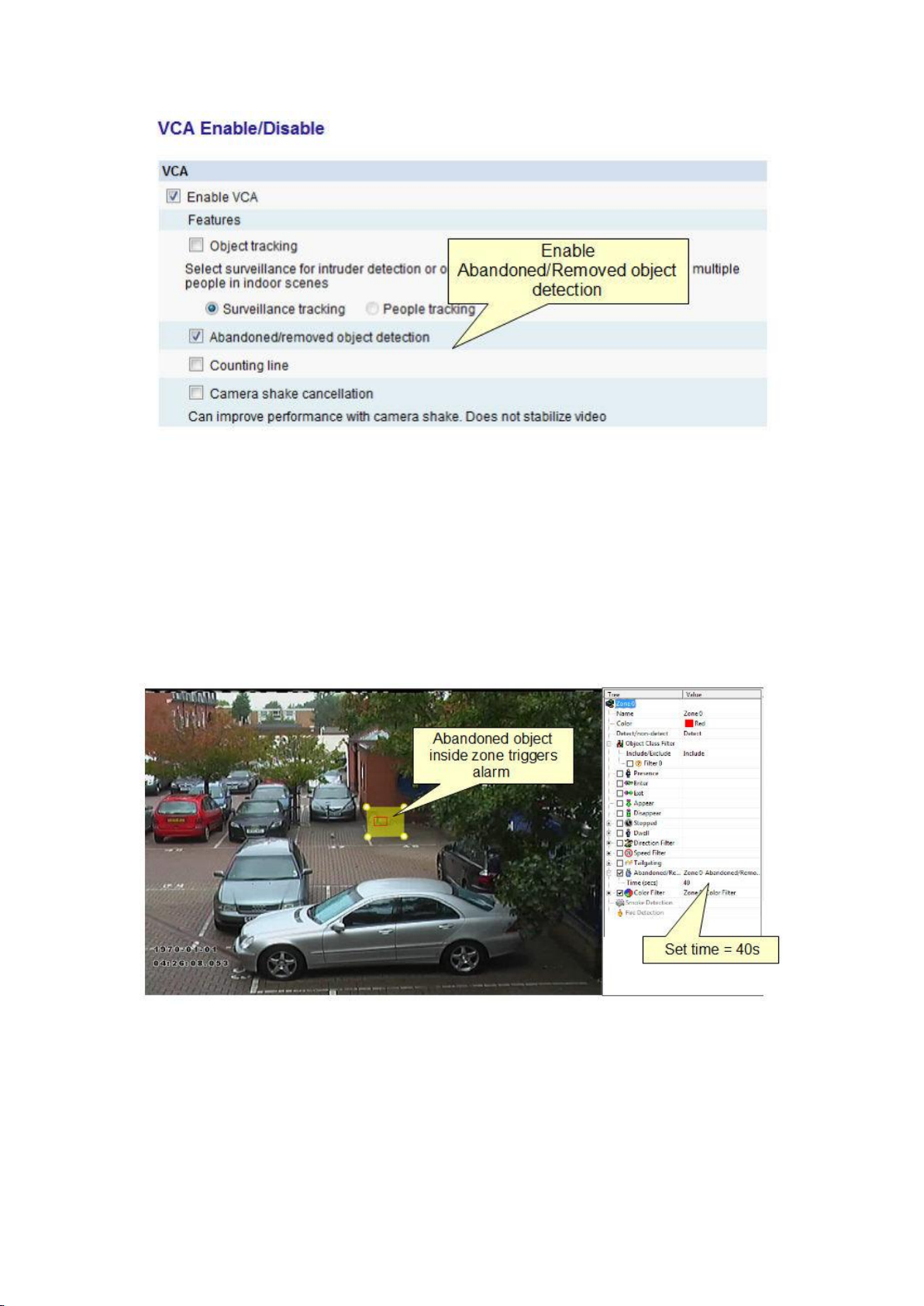
Ensure that abandoned/removed object detection is enabled by checking the
"Abandoned/removed object detection" box on the VCA Enable/Disable page.
32
Page 41
Configuration of Zones and Rules
NOTE: The algorithm used for abandoned and removed object detection is the same in each
case: it cannot differentiate between abandoned or removed objects. This is a fundamental
limitation of the algorithm and arises because it just analyses how blocks of pixels change
with respect to a background model that is constructed over time. When an object is
inserted into the background (abandoned) it looks the same to the algorithm as when an
object is removed from the background.
Enable the abandoned/removed object rule on the selected zone by checking the
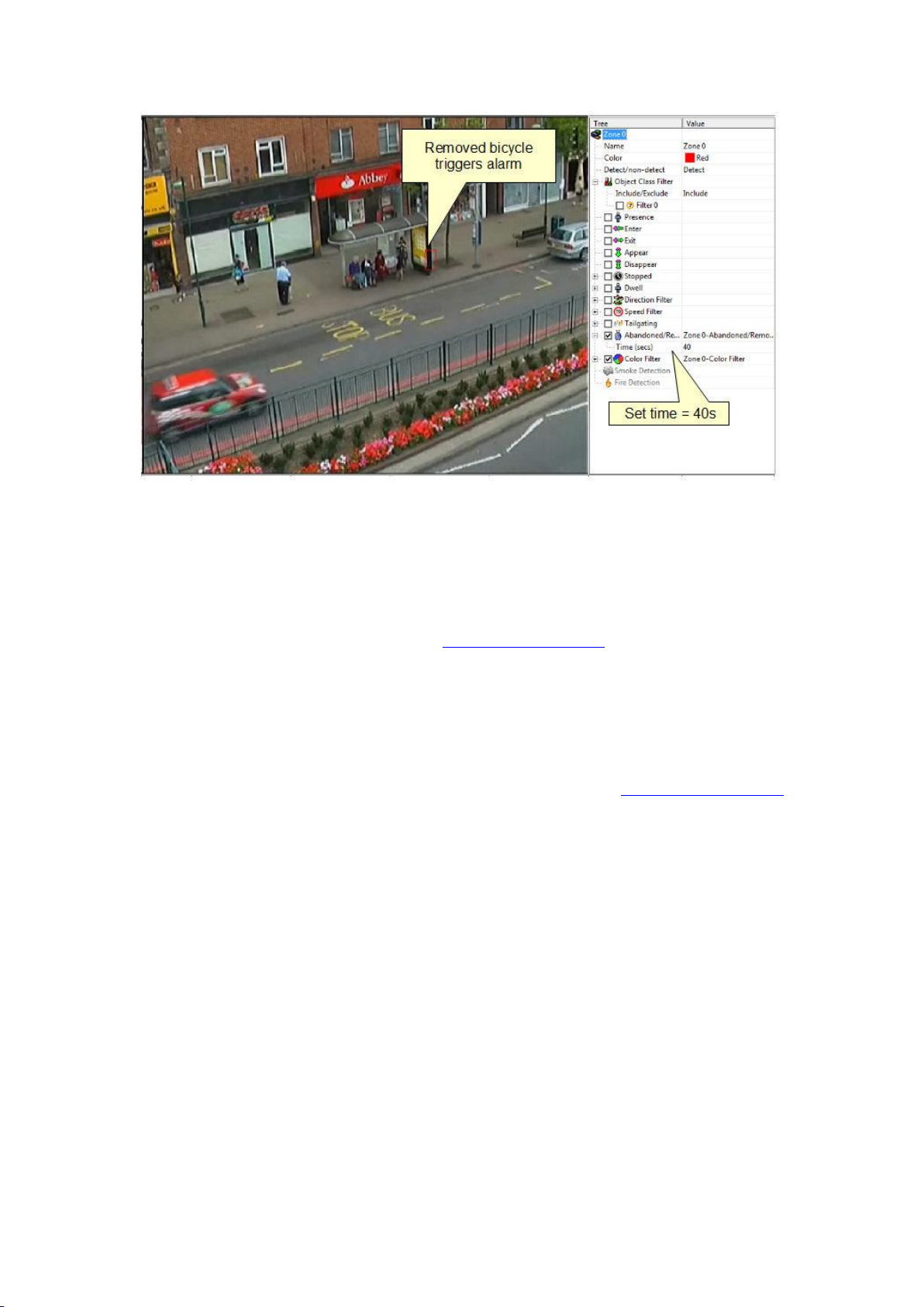
Abandoned/Removed Object box in the properties inspector. An object that is left inside a
zone for longer than the configured time period will trigger the rule and raise an alarm.
The following figure illustrates the abandoned/removed object detection rule detecting a
removed bicycle.
33
Page 42
Printed Documentation
Stationary Object Hold-on Time
The stationary object hold-on time is the time which the tracker will keep tracking an object
once it has been detected as stationary or abandoned/removed. After an
abandoned/removed object has been detected, the object will continue to be tracked for
the time configured determined by the stationary object hold-on time. The default value is
60 seconds, but this can be changed on the advanced settings page.
Diagnostic Data
In order to evaluate the performance of the abandoned/removed object detection and
troubleshoot issues in challenging circumstances, it's possible to enable the display of blobs.
The blobs show the underlying pixels detected as "interesting" by the algorithm. Note that
the blobs must be enabled to be transmitted in the metadata on the advanced settings page
for them to visible on the annotation overlay.
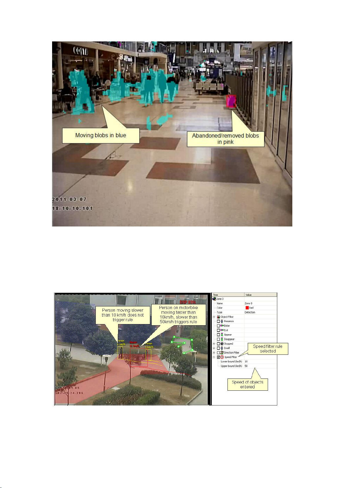
Moving blobs are displayed in blue whereas blobs that correspond to abandoned or
removed objects are displayed in pink.
34
Page 43
Configuration of Zones and Rules
Object Speed
Enable the object speed rule on the selected zone by checking the Speed Filter box in the
properties inspector. Adjust the lower and upper speed limits to suit the detection scenario.
Objects that travel within the bounds of the configured speeds, through a zone or over a line
trigger the rule and raise an alarm.
Note that the camera must be calibrated for this function to be available.
Counting Line
A counting line is a detection filter optimized for bi-directional object counting (e.g. people
or vehicles) in busier detection scenarios. Examples of such applications may include:
35
Page 44
Printed Documentation
People counting with overhead cameras in a retail environment.
Vehicle counting with overhead cameras on public highways.
The counting line filter can be enabled when the unit has been configured with
VCAcount/VCAaccess/VCAadvanced/VCApro license. In some scenes such as entrance with
camera over-head installed, the counting line typically will generate a higher accuracy count
than using the counters provided as part of VCAsurveillance.
NOTE: The maximum number of counting line filters that can be applied per video channel
is 5.
Enabling the Counting Line
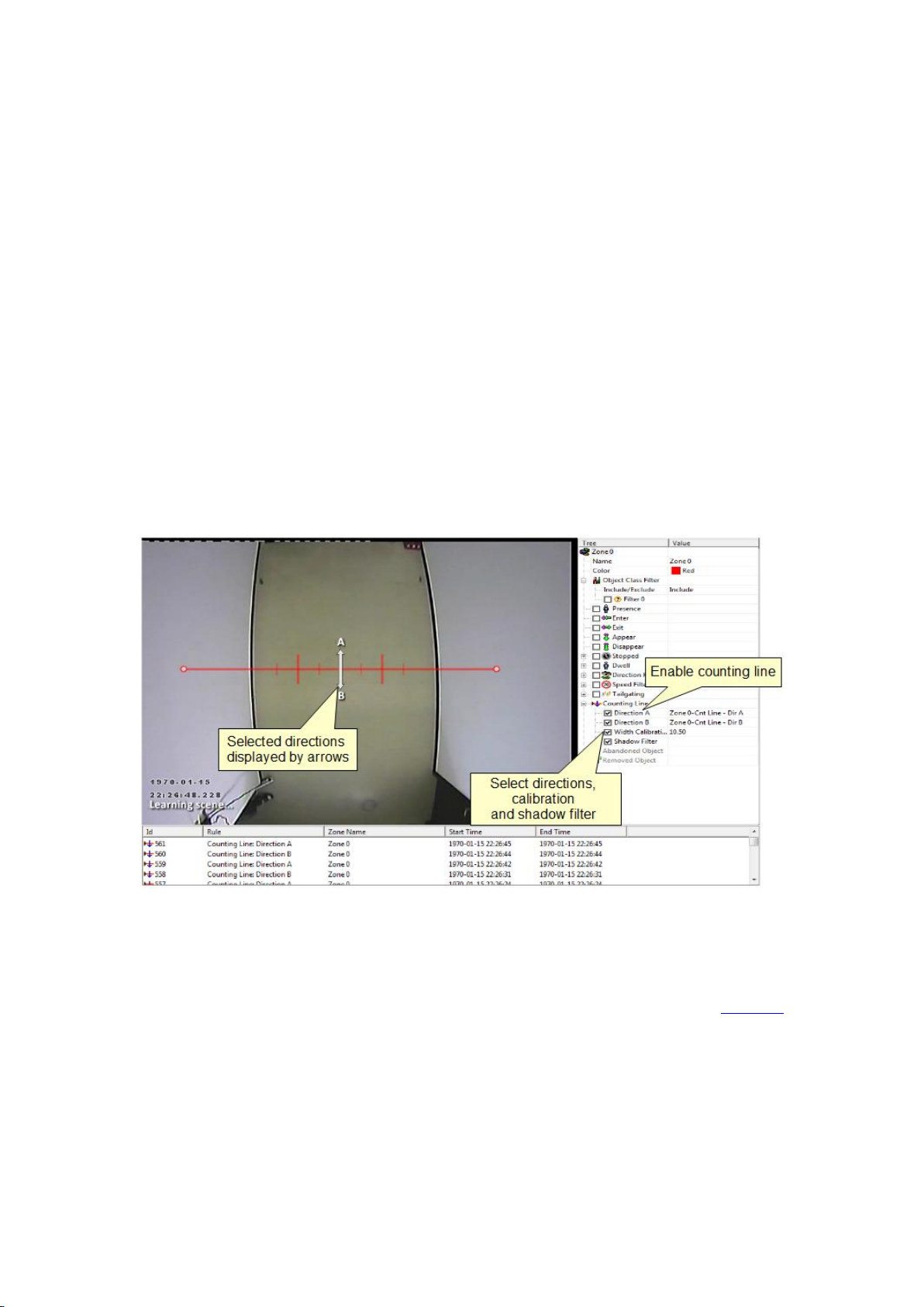
Enable the counting line filter on a detection line in the desired direction(s) by checking the
appropriate box in the properties inspector. An event is generated every time an object
crosses the line in the selected direction. If multiple objects cross the line together, multiple
corresponding events are generated. The events generated by the counting line can be tied
to counters in the normal manner.
Assigning Counters to Counting Lines
A counting line by itself simply generates events when an object to be counted is detected.
In order to actually count the events, counters (one for each direction) can be created and
configured to count the events generated by the line. To create counters, see the Counters
topic.
36
Page 45
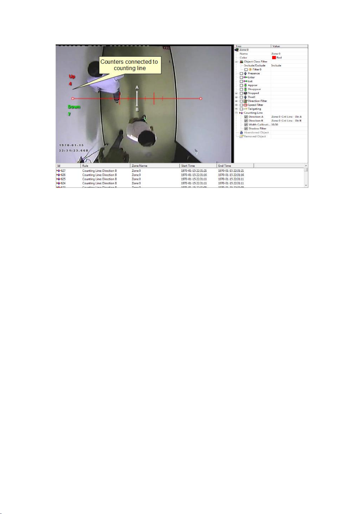
Calibrating the Counting Line
Configuration of Zones and Rules
In order to generate accurate counts, the counting line requires calibration. Unlike
VCAsurveillance, this cannot be performed at a general level for the whole scene using the
3D calibration tool. This is because the counting line is not always placed on the ground
plane: it may be placed at any orientation at any location in the scene. For example, a
counting line could be configured vertically with a side-on camera view.
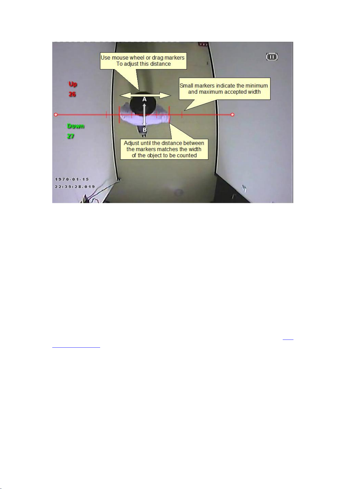
Instead of the 3D calibration tool, the counting line has its own calibration setting. Two bars
equidistant from the centre of the line represent the width of the expected object. This
allows the counting line to reject noise and also count multiple objects.
To calibrate the counting line:
Select the counting line with the mouse.
Check the "Width Calibration" box under the Counting Line rule in the property
inspector.
Use the mouse wheel or drag the calibration markers to adjust the distance between
the calibration markers until the distance is approximately the size of the objects to
be counted.
The calibration width is displayed on the property inspector under the counting line
rule. The figure which is displayed is the calibration width expressed as a percentage
of the image width. This figure can also be edited to change the calibration width.
The small markers on either side of the big markers indicate the minimum and
maximum width which is counted as a single object.
Apply the settings.
37
Page 46
Printed Documentation
Shadow Filter
The counting line features a shadow filter which is designed to remove the effects of object
shadows affecting the counting algorithm. Shadows can cause inaccurate counting results by
making an object appear larger than its true size or by joining two or more objects together.
If shadows are causing inaccurate counting, the shadow filter should be enabled by selecting
the "Shadow Filter" check box for the line. It is recommended that the shadow filter only be
enabled when shadows are present because the algorithm can mistake certain parts of an
object for shadows and this may lead to worse counting results.
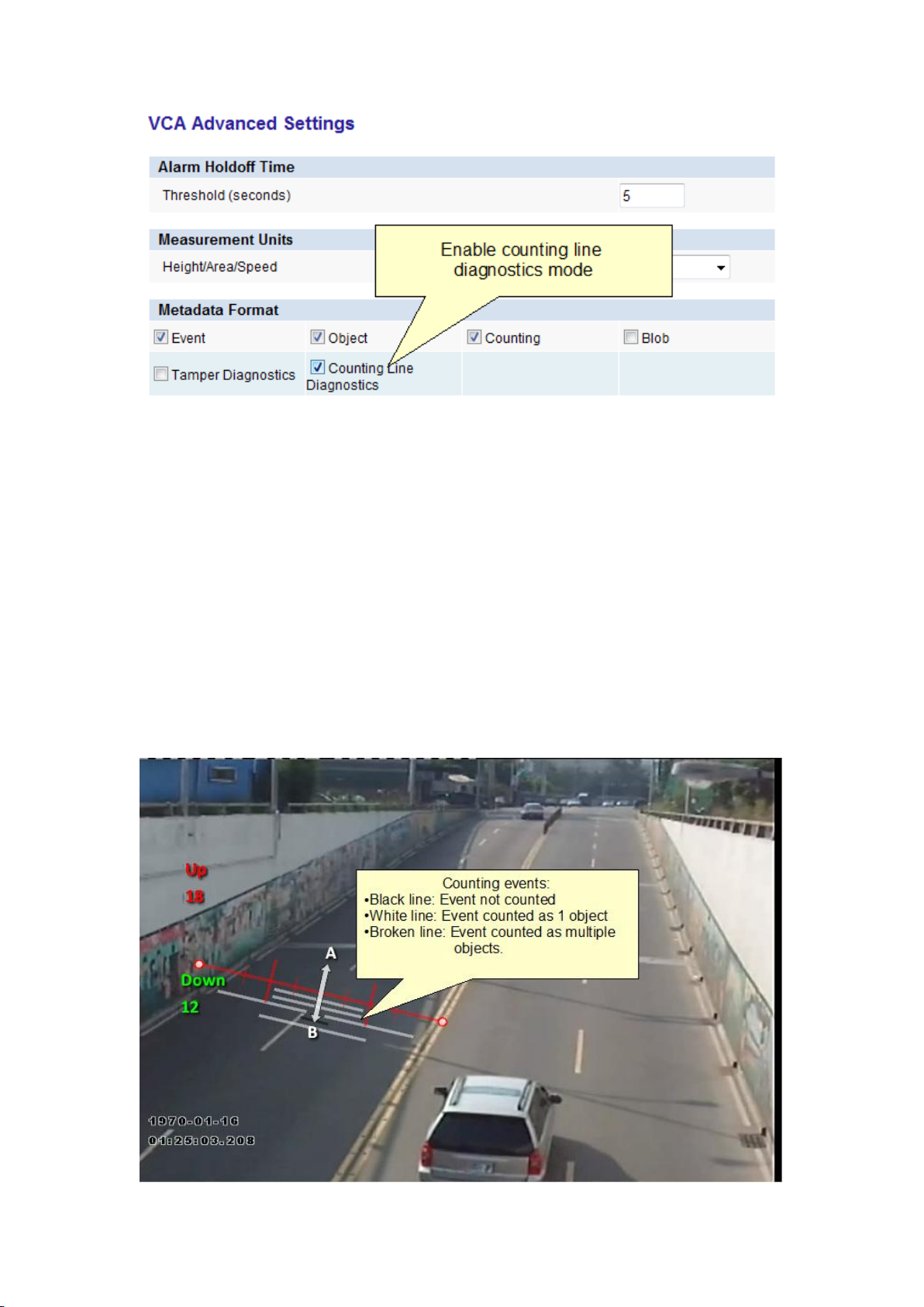
Calibration Diagnostics Mode
To enable the user to more accurately configure the calibration for the counting line, there is
a diagnostics feature which can be enabled to provide feedback of the counting results. To
enable this mode, select the "Metadata Format" ->"Counting Line Diagnostics" on the VCA
Advanced Settings page .
38
Page 47
Configuration of Zones and Rules
When the diagnostics metadata is enabled, the diagnostics will appear as black and white
lines on either side of the counting line on the Zones and Rules page. Each line represents an
object which was detected by the counting algorithm. The width of the line shows the width
of the object detected by the line. The last 5 detections are displayed for each direction with
the latest one appearing closest to the counting line. Each detection is counted as a number
of objects based on the current width calibration. This is shown as follows:
Black line: Event not counted
Solid white line: Event counted as one object
Broken white line: Event counted as multiple objects indicated by the number of line
segments.
Using the feedback from the diagnostics, the width calibration can be fine tuned to count
the correct sized objects and filter out spurious detections.
39
Page 48
Printed Documentation
Smoke Detection
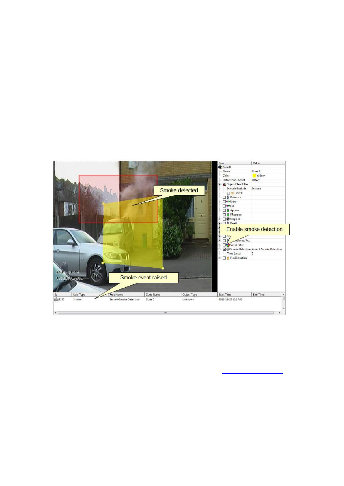
Enable the smoke detection filter by checking the Smoke Detection box in the properties
inspector. If smoke is detected inside the corresponding detection zone alerts are raised in
the alarm log window. The Time setting specifies how long smoke should be detected for,
before the smoke detected event is raised.
WARNING
The smoke detection filter does not comply with any detection standards and should not
be used as a safety device. It should be installed in addition to certified safety devices and
used only to supply additional information.
Diagnostic Data
In order to evaluate the performance of the smoke detection and troubleshoot issues in
challenging circumstances, it's possible to enable the display of smoke blobs. The blobs show
the underlying pixels detected as potentially being smoke by the algorithm. Note that the
blobs must be enabled to be transmitted in the metadata on the advanced settings page for
them to visible on the annotation overlay.
Blobs that are potentially detected as smoke are displayed in white.
40
Page 49
Configuration of Zones and Rules
Fire Detection
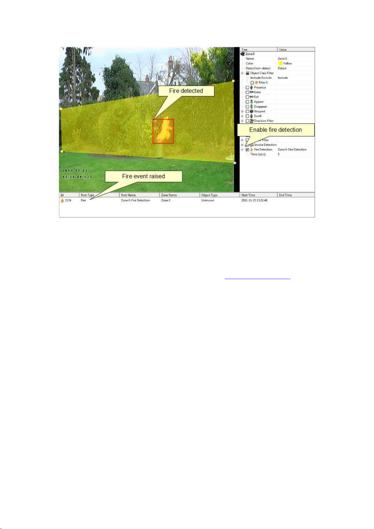
Enable the fire detection filter by checking the Fire Detection box in the properties inspector.
If fire is detected inside the corresponding detection zone alerts are raised in the alarm log
window. The Time setting specifies how long fire must be detected for, before the fire event
is raised.
WARNING
The fire detection filter does not comply with any detection standards and should not be
used as a safety device. It should be installed in addition to certified safety devices and
used only to supply additional information.
41
Page 50
Printed Documentation
Diagnostic Data
In order to evaluate the performance of the fire detection and troubleshoot issues in
challenging circumstances, it's possible to enable the display of fire blobs. The blobs show
the underlying pixels detected as potentially being fire by the algorithm. Note that the blobs
must be enabled to be transmitted in the metadata on the advanced settings page for them
to visible on the annotation overlay.
Blobs that are potentially detected as fire are displayed in red.
42
Page 51
Configuration of Zones and Rules
Object Colour Filter
NOTE: The object colour filter requires a VCApro license, and the Tracking mode must be set
to People Tracking on the VCA Enable/Disable page.
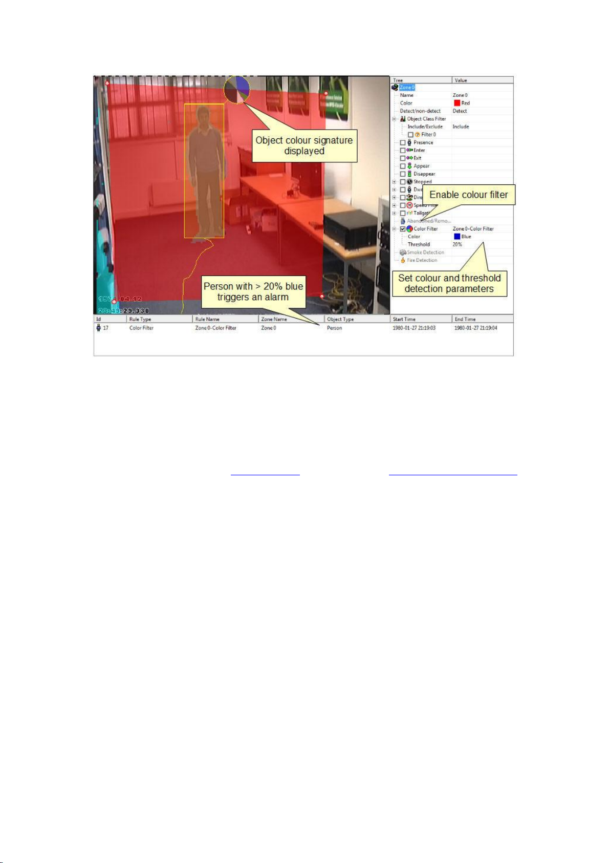
Enable the object colour filter by checking the corresponding box in the properties inspector
and click apply.
Specify the colour and threshold (amount of colour within an object) detection properties.
An object colour filter alarm is raised when an object that contains more than the specified
threshold of the specified colour is tracked inside the zone.
43
Page 52
Printed Documentation
Object Colour Signature
For every object that's tracked, a colour signature is calculated and transmitted in the
metadata stream. The colour signature can be displayed as an overlay on the screen to help
the selection of the parameters for the colour filter.
In order for the colour signature to be displayed, the colour signature must be enabled in
the metadata settings on the advanced page and the option to display the colour signature
should be selected.
44
Page 53
Counters
Counters
VCAsys also supports object counting. Any combination of detection zones or lines can be
assigned to a counter. Counters can be configured to perform any combination of
incremental, decremental or occupancy counting. Counter configuration is managed through
the properties inspector in a similar way to the zone configuration.
Topics in this section:
Creating Counters
Assigning Rules to Counters
Creating Counters
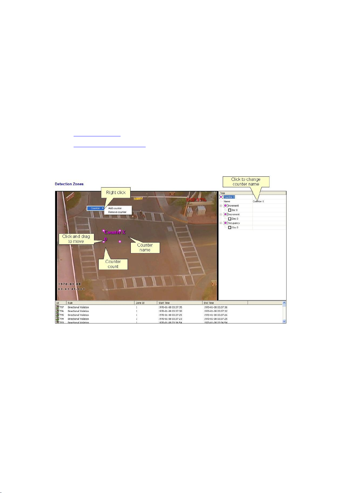
To create a counter simply click the right mouse button and select Counters... Add Counter.
The counter name can be changed by clicking in the Name box on the rules control.
Assigning Rules to Counters
Counters count triggers generated by rule violations. For example, if it is required to count
the number of objects entering a zone, a zone must initially be configured to raise an alarm
every time an object enters it. The zone can then be assigned to a counter and the counter
will count the objects according to the type of counting required (increment, decrement,
occupancy).
45
Page 54
Printed Documentation
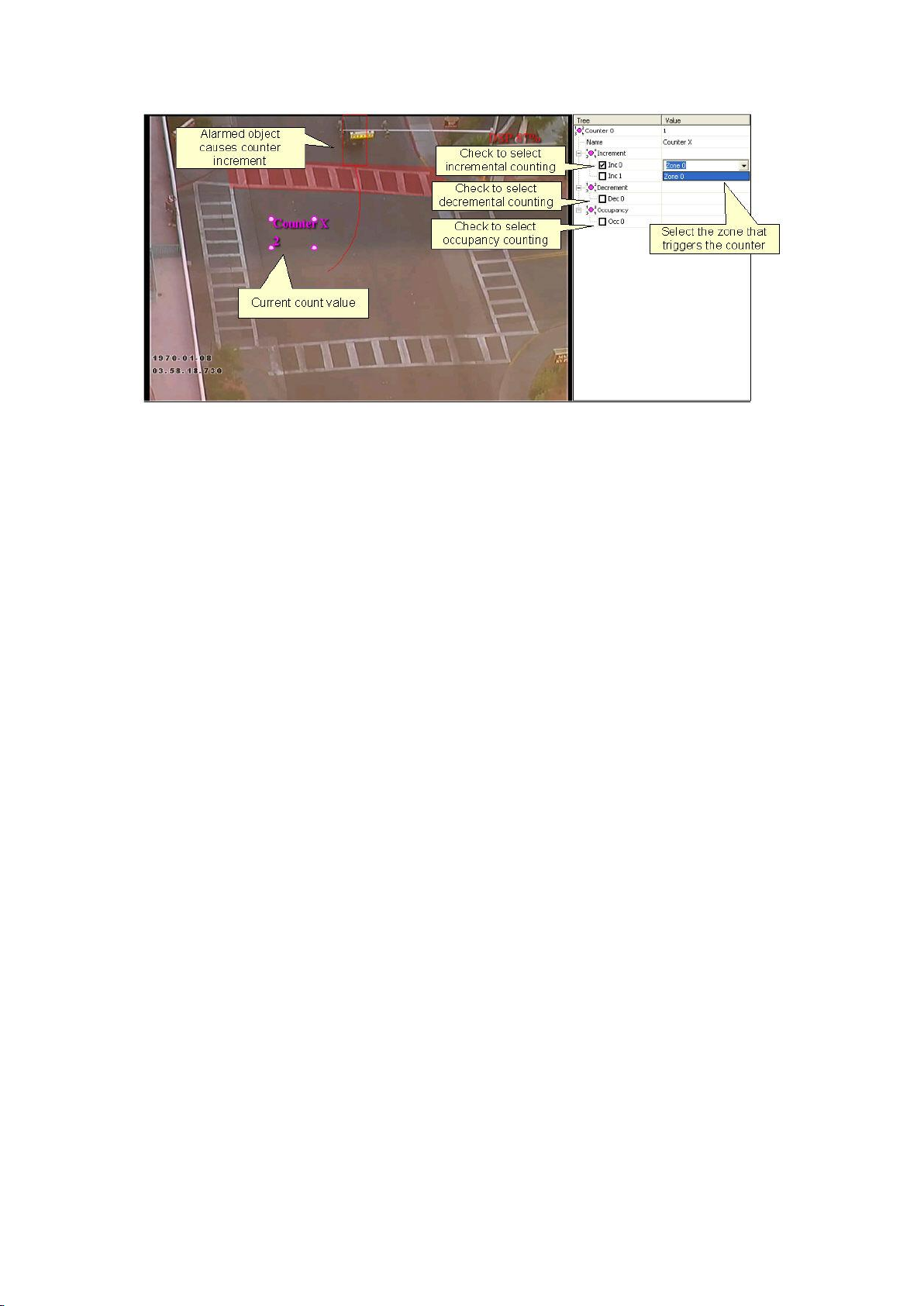
In this example the red zone is configured to trigger when object travelling in the north
direction are detected. The counter has been configured to increment the count whenever
the zone (Zone 0) is triggered. Currently two objects have been counted.
Incremental Counters
When a zone is assigned to an incremental counter, the count will increment by 1 every time
the zone is triggered.
Decremental Counters
When a zone is assigned to a decremental counter, the count will decrement by 1 every time
the zone is triggered.
Occupancy Counters
When a zone is assigned to an occupancy counter, the counter displays the number of active
triggers in the zone. E.g. if there are 2 objects in the zone that triggered the detection rule,
then the count will display 2.
46
Page 55

Counter Storage and Reporting
Counter Storage and Reporting
The counter storage and reporting service allows the device to store the values of any
configured counters at regular intervals in up to 4 on-board databases. Any of the databases
can be queried by the user to generate tables, graphs and reports of the data stored in the
database. The database interface also supports direct connections from Microsoft Excel in
order to allow further processing within Excel.
The counter storage and reporting configuration is accessed by clicking the Counter
Reporting link from the device menu.
NOTE: A VCApro or VCAcount license is necessary in order to take advantage of the counter
storage and reporting functionality.
The configuration of the counter storage and reporting module comprises 2 areas:
The database service
The reporting service
Database Service
The database service manages up to 4 databases. It logs the values of all configured counters
to the database at pre-configured, regular intervals. See the Database Service Configuration
page for more details.
Reporting Service
The reporting service allows the user to query the databases and generate graphs, tables,
reports and even export the data into Microsoft Excel for further processing. See the
Reporting Service page for more details.
Database Service
The database service is responsible for logging all of the counter values at regular intervals
to up to 4 database tables.
To access the Database Service configuration page, click the Database Service tab under the
Counter Reporting menu option.
47
Page 56
Printed Documentation
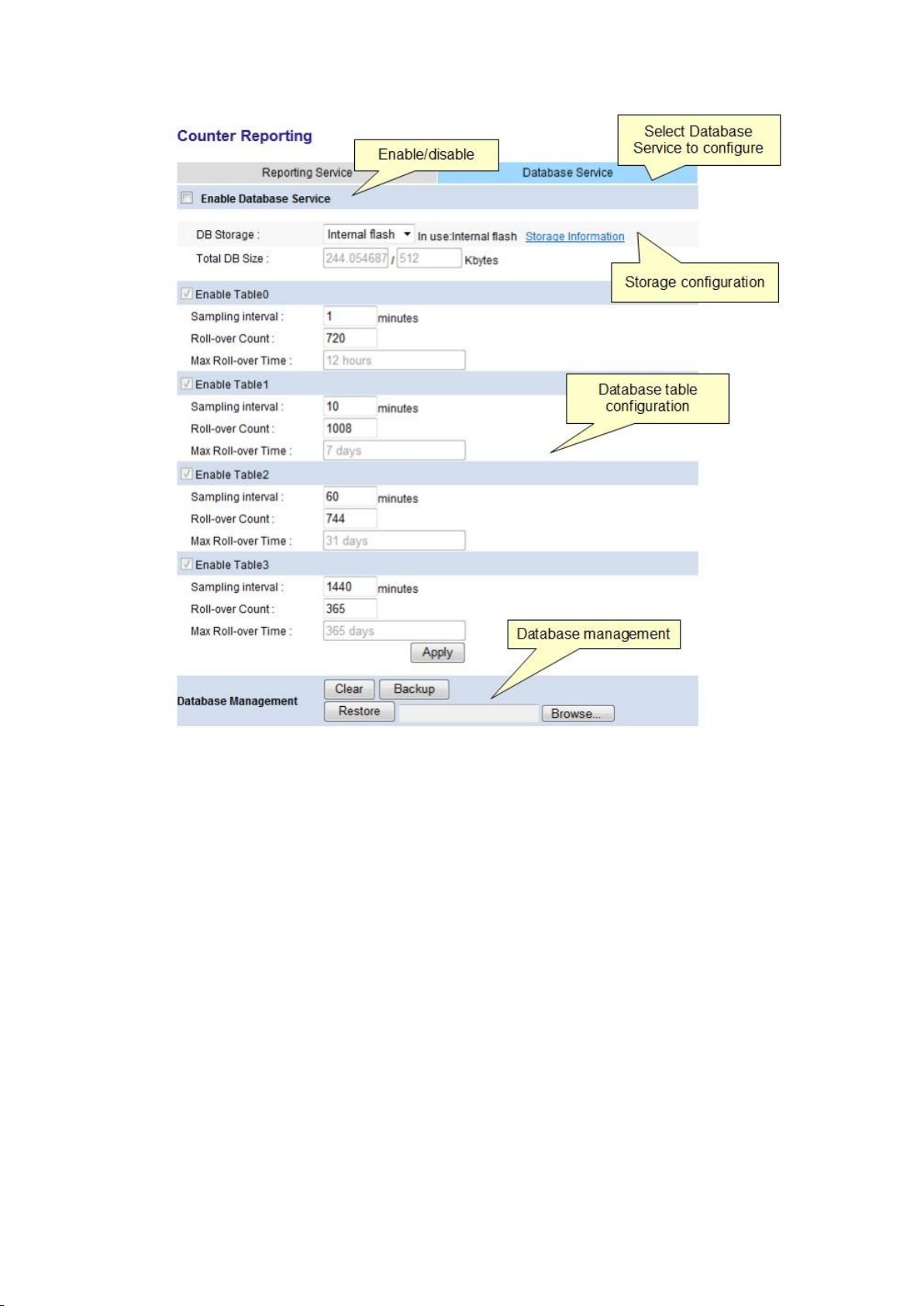
Enable Database Service
The control for enabling/disabling the database service. This also functions as the master
switch for all other counting and reporting functions - if the database service is not enabled,
none of the other services will function.
DB Storage
Allows the user to select where the database tables are stored in physical memory. It's
possible to select internal flash, SD card or USB memory stick. If the selected memory device
is not available, internal flash will be used instead. The in use: label shows which storage
medium is currently being used to store the database tables.
Total DB Size
The maximum size of the database when internal flash is selected as the storage medium is
512KB. The display shows how much storage is in use out of the total available. If the
configuration of the database tables would cause the storage requirement to exceed the
maximum the user is warned before the settings can be applied.
Database Table Configuration
48
Page 57

Counter Storage and Reporting
The database allows up to 4 tables to be configured (0-3). Each table can sample the counter
values at different intervals, thus allowing reports that cover different granularities and time
windows to be generated by the user.
Tables must be enabled in-order. For example, Table 0 must be enabled before Table 1 can
be enabled.
Sampling Interval
How frequently the counter values are sampled and stored to the database. Specified in
minutes.
Roll-over Count
The total number of records to store in the database table. When this number of records
have been added to the table, the table wraps-around and overwrites the oldest data.
Max Roll-over Time
Shows the maximum time that the table will hold counting data for. Calculated as follows:
Max Roll-over Time (minutes) = Sampling Interval x Roll-over Count
Database Management
Functions for managing the database.
Clear
Wipes all data from all database tables.
Backup
Allows the user to download a backup of the database tables into a file that can be restored
at a later date.
Restore
Restore a previously downloaded backup back into the database tables.
Reporting Service
The reporting service is the user-interface into the counter storage and reporting
functionality. It allows the user to query the database service to generate reports, tables and
even export data to Microsoft Excel for further analysis.
49
Page 58
Printed Documentation
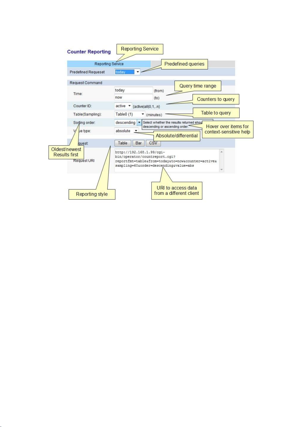
The essence of the counter reporting page is to select the query parameters and then select
whether it should be displayed as a table, bar or exported to CSV. There are a number of
pre-defined requests that offer quick and easy way to get started.
Every element on the counter reporting page has context-sensitive help: just hover the
mouse over the item in question to get detailed information about the values that can be
entered into that field.
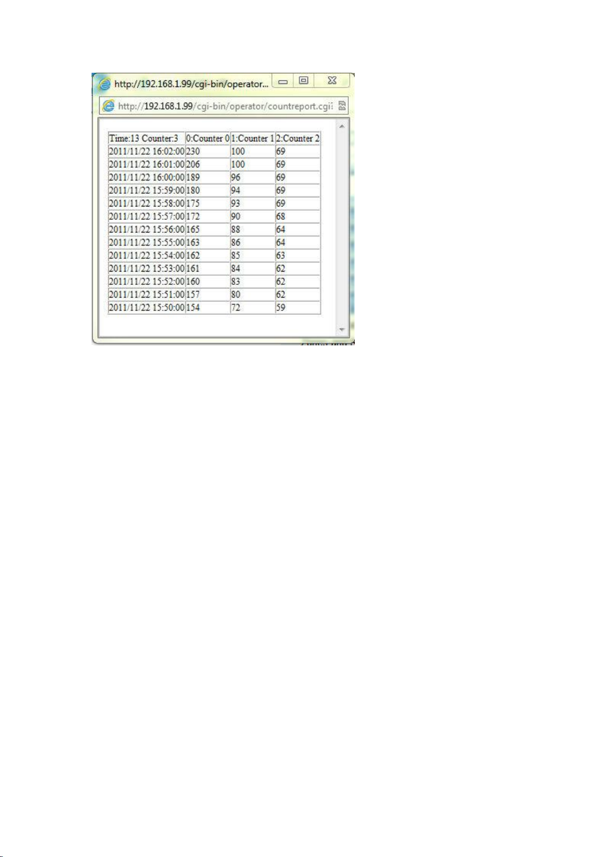
Tabular Reporting
Enter the query parameters and click the Table button. The data is displayed as a table:
50
Page 59
Counter Storage and Reporting
Bar Graph Reporting
Clicking the Bar button pops up a new window with a bar graph of the results. The colour of
each bar matches the colour of the counter on the Zones & Rules configuration page.
51
Page 60

Printed Documentation
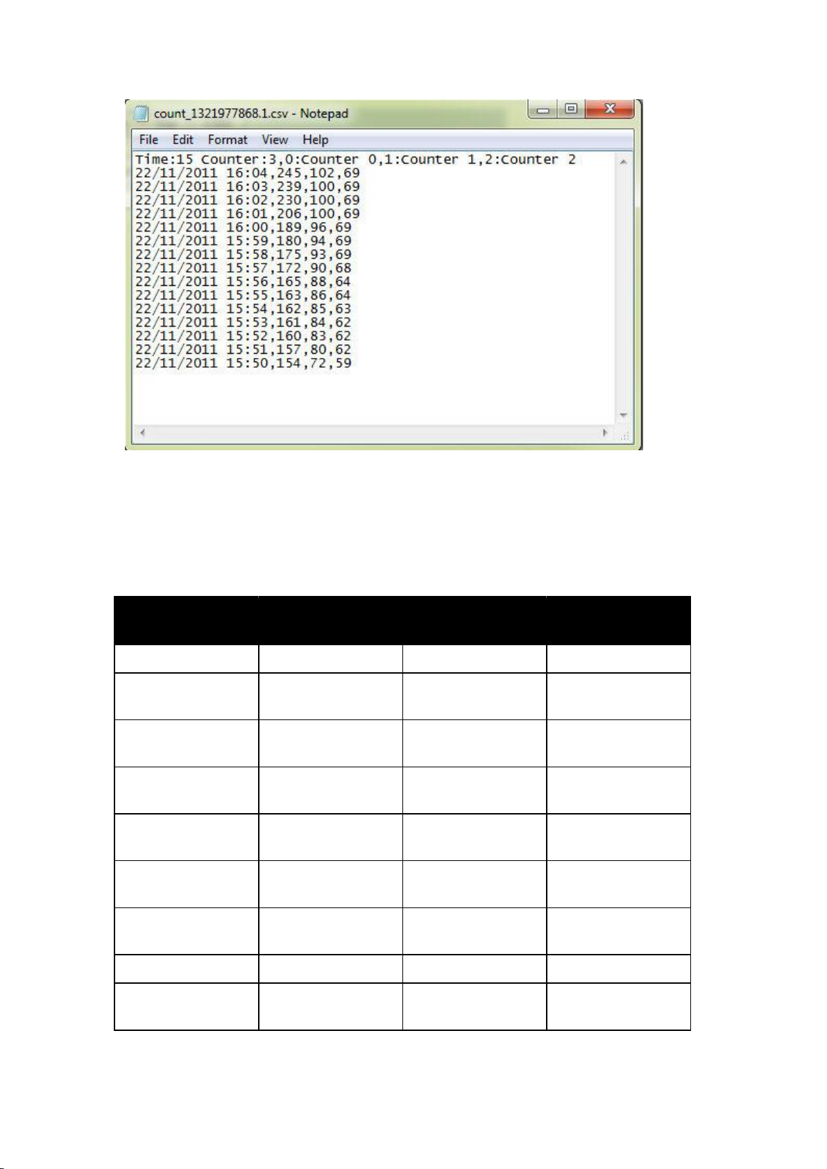
CSV Export
Clicking the CSV button offers a file that contains the results of the query in commaseparated-variable format.
52
Page 61
Counter Storage and Reporting
Predefined
Request
From
To
Default Sampling
Period
One hour
now - 1 hour
now
1 minute (Table 0)
Today
today @ 0:00
now
10 minutes (Table
1)
Yesterday
yesterday @ 0:00
today @ 0:00
10 minutes (Table
1)
One day
now - 1 day
now
10 minutes (Table
1)
This week
sunday @ 0:00
today
60 minutes (Table
2)
Last week
Last sunday @ 0:00
Last saturday @
24:00
60 minutes (Table
2)
One week
now - 1 week
now
60 minutes (Table
2)
This month
1st of this month
now
1 day (Table 3)
Last month
1st of last month
Last day of last
month
1 day (Table 3)
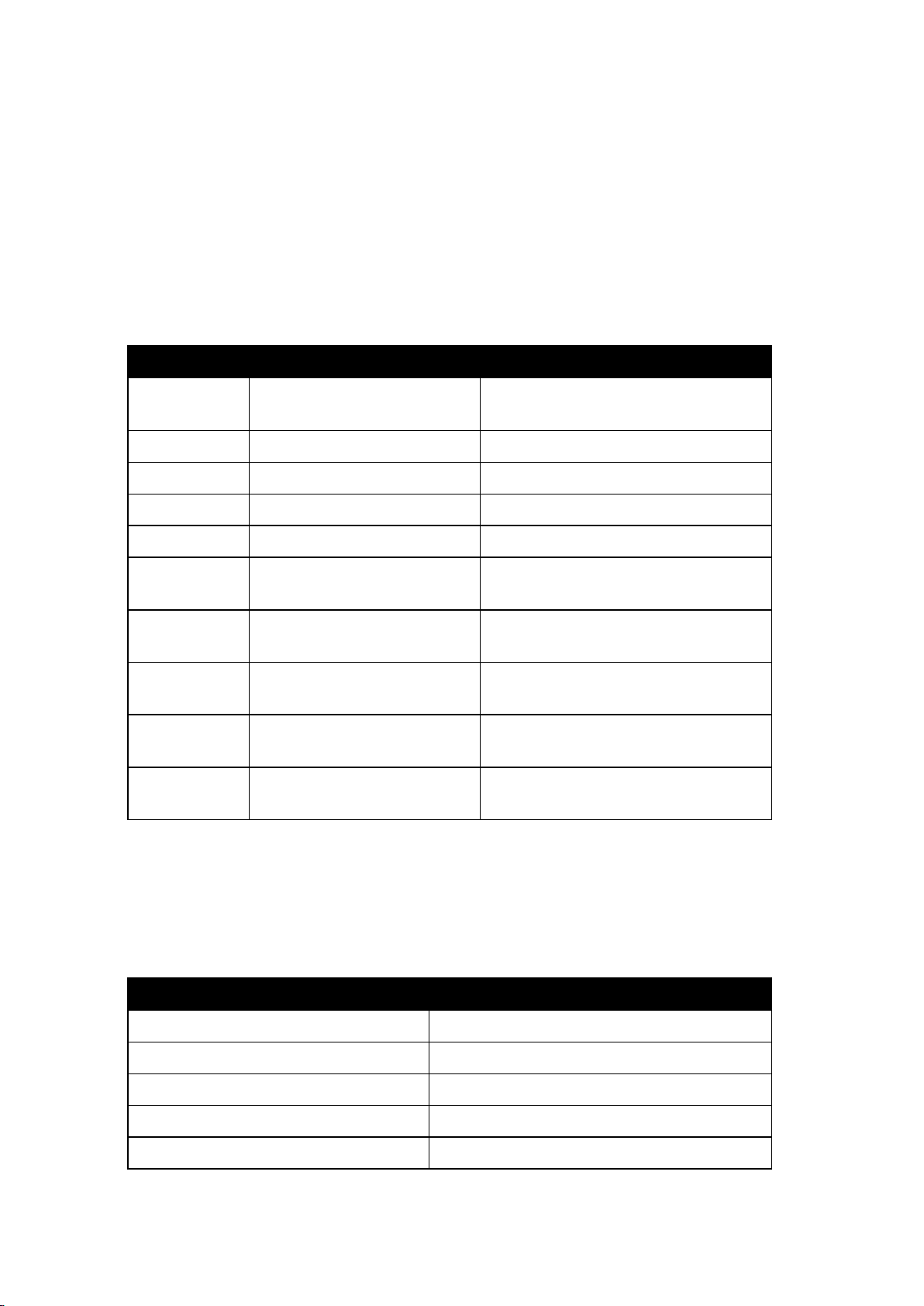
Predefined Requests
The counter reporting service has a number of pre-defined requests that reflect the most
common usage scenarios. It's possible to just select one of these pre-defined requests and
click one of the reporting modes directly to generate a report in a very short amount of time.
The requests available are:
53
Page 62
Printed Documentation
Option
Details
Example
Absolute date
and time
YYYY/MM/DD hh:mm
2011/10/21 09:00
Seconds
Decimal integer
3600 (=1 hour)
now
The current time
now means 2011/10/21 09:00
today
0:00 on the current day
today means 2011/10/21 0:00
yesterday
0:00 on the day before today
yesterday means 2011/10/20 0:00
sunday,
monday,..
Any day of the week @ 0:00
thursday means 0:00 on the previous
Thursday
this_week
0:00 on the first day of the
week
this_week means 0:00 on the previous
Sunday
last_week
0:00 on the first day of last
week
last_week means 0:00 on the Sunday
before last
this_month
0:00 on the first day of this
month
this_month means 0:00 on the first
day of this month
last_month
0:00 on the first day of last
month
last_month means 0:00 on the first
day of last month
Example
Meaning
now
2011/05/23 14:20
today
2011/05/23 00:00
now-01:00
2011/05/23 13:20
today 04:00
2011/05/23 04:00
today-04:00
2011/05/22 20:00
In each case, the predefined queries populate the rest of the fields on the page, so it's
simple to use a predefined query and then change just a couple of fields to customise it.
Command Request
In addition to using the predefined requests it's possible to select all query parameters
manually to query any combination of data. The options available are described in the
following section.
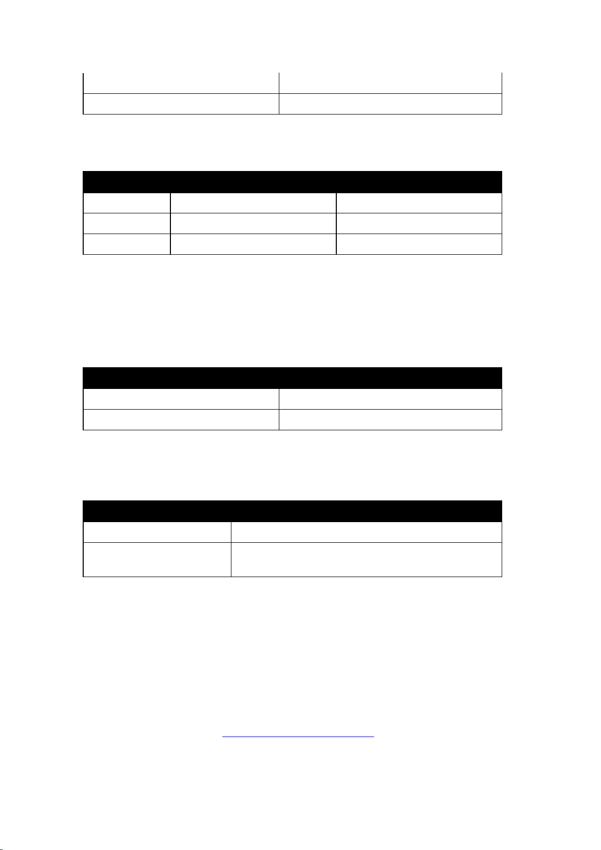
Time
The time bounds of the query. Specify the from and to times in the fields provided. The
syntax is as follows:
Time and dates can also be modified and combined with the simple arithmetic operators +
and - to perform querying relative to predefined keywords. Examples of the use of the
operators are as follows.
Assuming that the current time is 2011/05/23 14:20 Monday
54
Page 63
Counter Storage and Reporting
yesterday+3600
2011/05/22 01:00
sunday 06:00
2011/05/22 06:00
Counter ID
Details
Example
active
All currently displayed counters
1,4,5,6
all
All counters
0-19
one of 0-19
An individual counter id
1
Sorting order
Details
descending
The newest records are returned first
ascending
The oldest records are returned first
Value Type
Details
absolute
The actual counter values are returned
difference
The difference between this and the previous sample is
returned
Counter ID
Allows specification of which counters are included in the request, can be any one of:
Table (Sampling)
Specifies the table to query. The sampling interval in minutes is displayed in parentheses.
Sorting Order
Specifies how to order the results returned from the query. Can be one of:
Value Type
Specifies the results returned should be absolute counts or the difference between the
current and previous sample. Can be one of:
Request
Click one of these buttons to generate either a table, bar chart or CSV output based on the
specified query parameters.
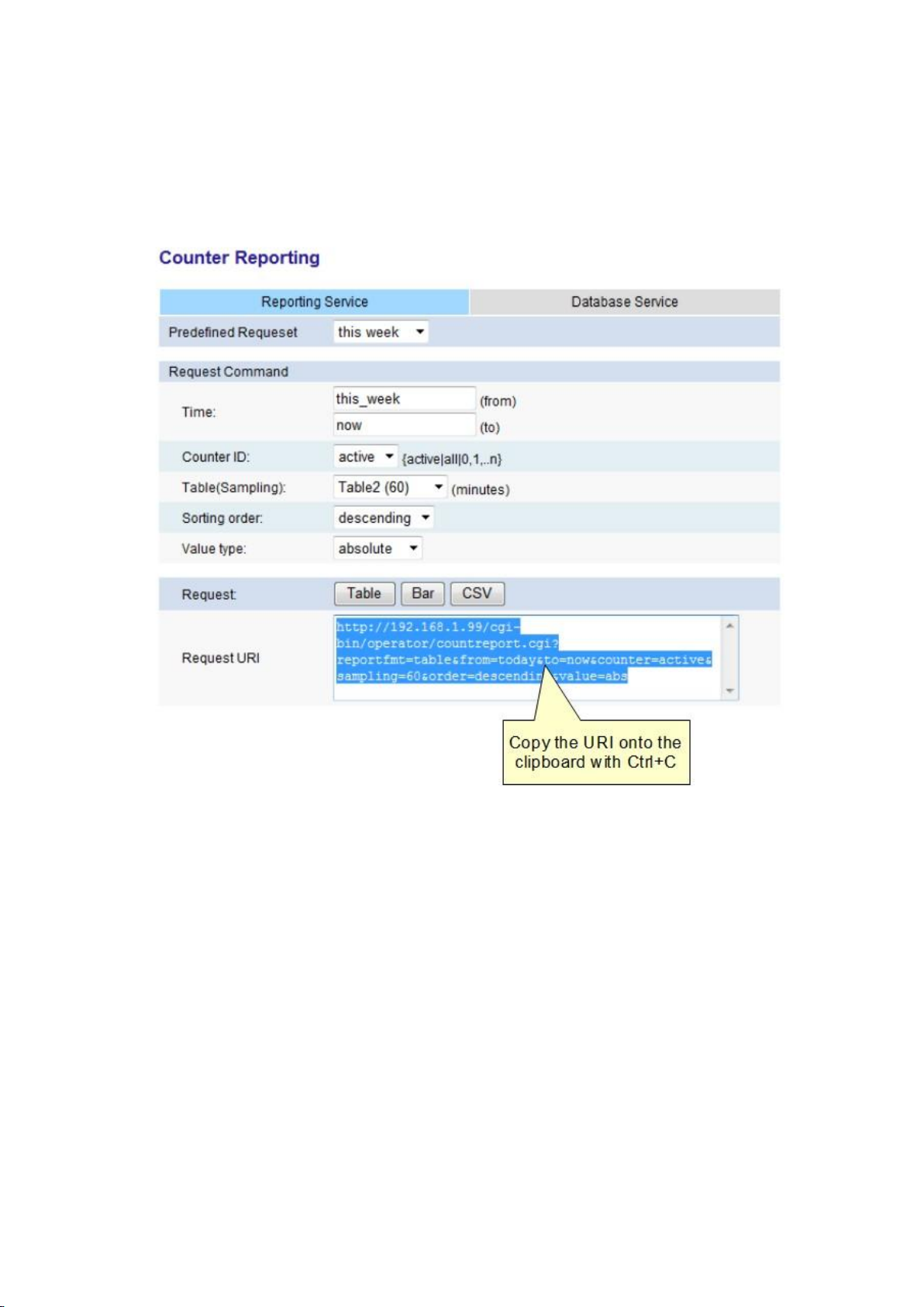
Request URI
The Request URI is the link that identifies the query specified by the field values. It's possible
to copy and paste this link in any browser to generate a data table that contains the results
of the query. One specific application of this method is to import the data as a real-time feed
into Microsoft Excel. See the Importing Data to Microsoft Excel topic for more information.
Importing Data into Microsoft Excel
55
Page 64
Printed Documentation
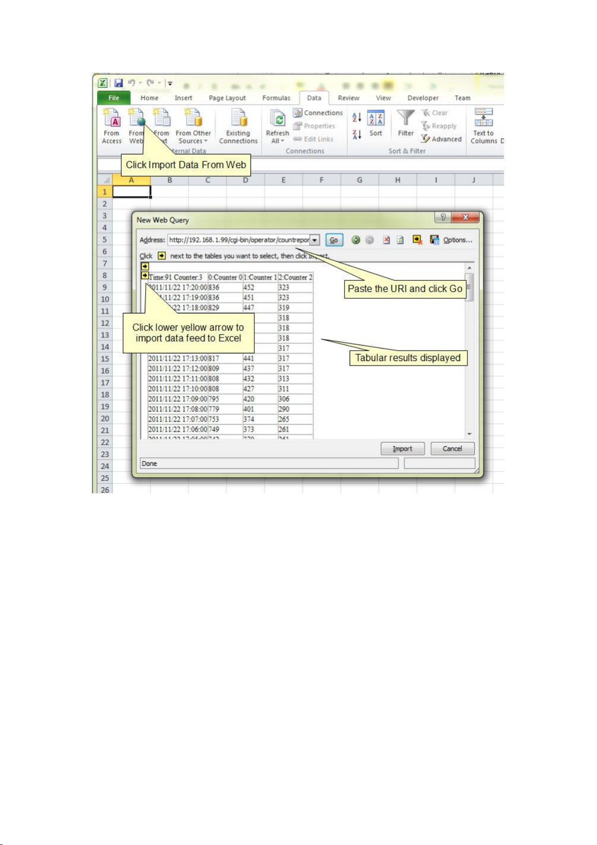
The counter reporting service is compatible with Microsoft Excel's Import Data From Web
function which allows users to extract a real-time data feed from one or many cameras and
then use Excel's powerful data analysis functions to perform further data processing.
On the counter reporting page, set up the query to generate the data view required. Then
copy the URI from the Request URI box to the clipboard.
Open up Excel and import the data feed as illustrated below:
56
Page 65
Counter Storage and Reporting
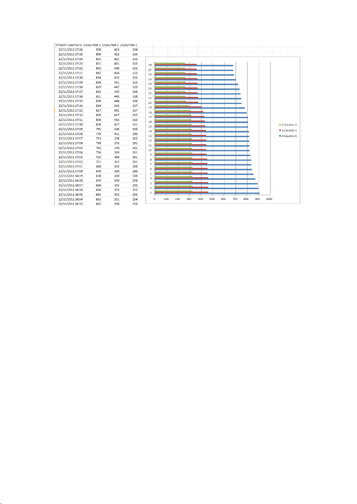
The data is then displayed in Excel and can be processed further. In this example, the three
counters have been added to a bar chart.
57
Page 66
Printed Documentation
58
Page 67

Camera Calibration
Camera Calibration
Camera calibration is required in order for the VCA engine to classify objects into different
object classes. Once the camera has been calibrated, the engine can infer real-world object
properties such as speed, height and area and classify objects accordingly.
Camera Calibration Topics
Calibration Page Elements
Calibrating a Camera
Advanced Calibration Parameters
Vertical Field of View
Measurement Units
Calibration Page Elements
The following describes the purpose of each element of the calibration page. To get started
calibrating straight away, see the Calibrating a Camera topic.
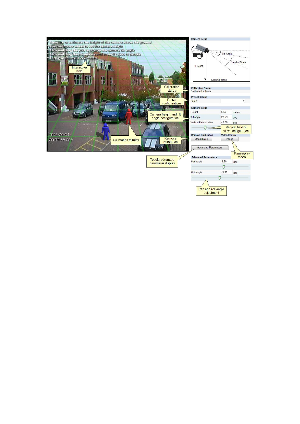
3D Graphics Overlay
During the calibration process, the features in the video image need to be matched with a
3D graphics overlay. The 3D graphics overlay consists of a green grid that represents the
ground plane. Placed on the ground plane are a number of 3D mimics that represent the
dimensions of a person with the current calibration parameters. The calibration mimics are
used for verifying the size of a person in the scene.
Mouse controls
The calibration parameters can be adjusted as follows:
Click and drag the ground plane to change the tilt angle.
Use the mouse wheel to adjust the camera height.
Drag the slider to change the vertical field of view.
59
Page 68
Printed Documentation
Other Graphical Tools
There are a number of other graphical tools that can be used to make the calibration process
simpler and more accurate.
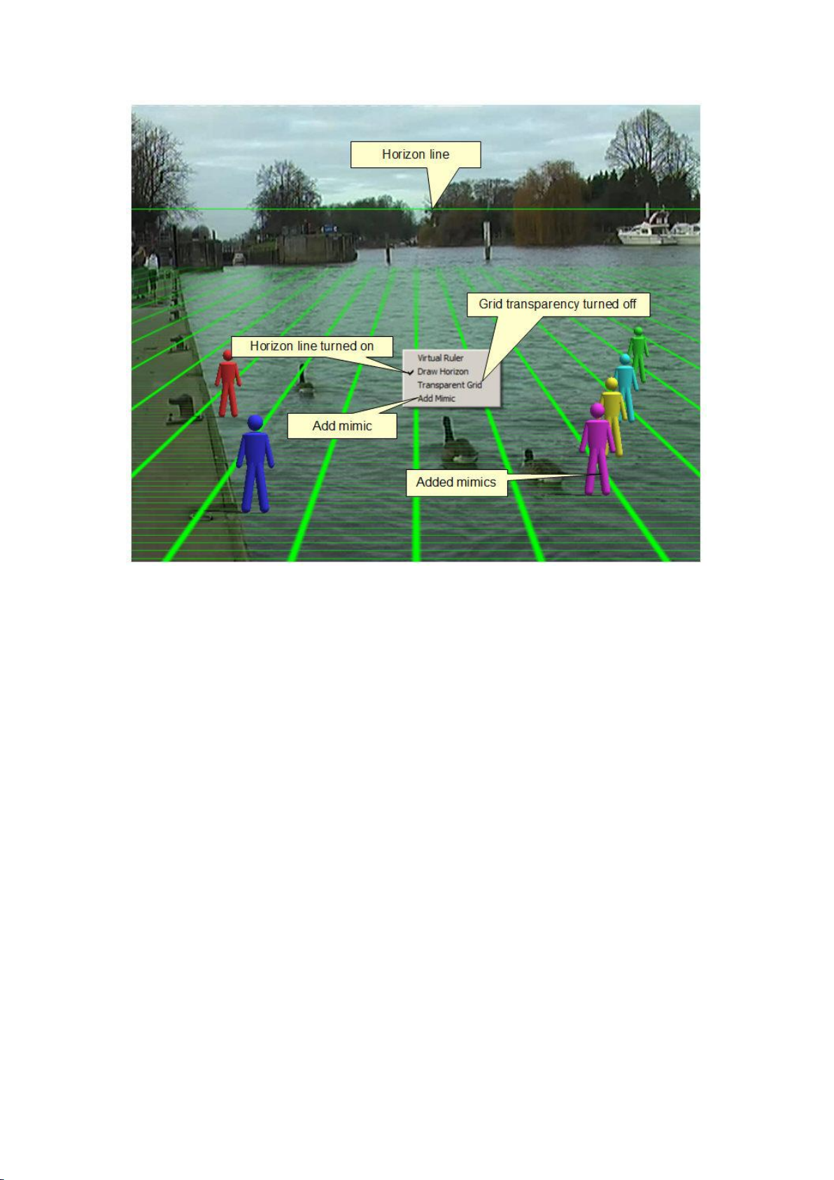
Horizon Display
The horizon can be displayed by right clicking and checking the menu option. If the horizon is
visible in the video, it is possible to use this to set the tilt angle. Drag the grid until the
horizon in the video matches the graphical horizon.
Additional Mimics
Additional mimics can be added to verify the calibration configuration. Select the Add Mimic
option from the menu.
Grid Transparency
By default the ground plane is displayed in transparent mode such that the video is clearer.
The transparent grid can be toggled by selecting the corresponding menu option.
60
Page 69
Camera Calibration
Virtual Ruler
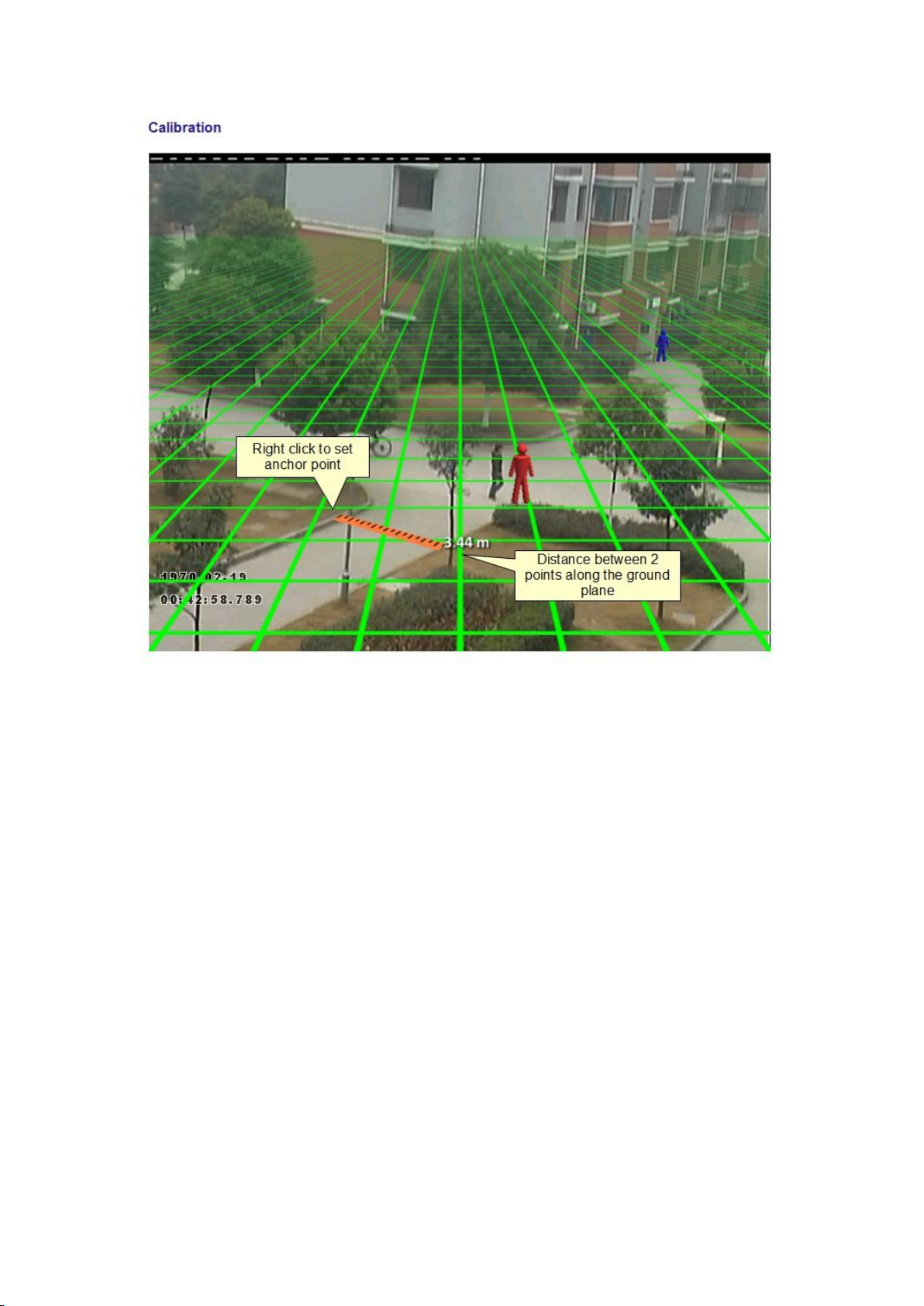
The calibration configuration control supports a virtual ruler. This can be useful for
measuring distances along the ground plane to objects of known size such as road lane
widths, car park space widths etc. The virtual ruler is effectively a "measurement stick" that
measures the distance between two points along the ground plane (not heights).
To use the virtual ruler, simply right click anywhere a point on the ground plane to anchor
one end of the ruler and select the option from the menu. It is then possible to move the
other end of the ruler around the ground plane to measure the distance between the anchor
point and the current mouse position.
To exit from the virtual ruler mode, click the right button. The ruler disappears.
61
Page 70
Printed Documentation
Calibrating a Camera
Calibrating a camera is necessary in order to estimate object parameters such as height, area,
speed and classification. If you know the height, tilt angle and vertical field of view
corresponding to your installation, you can simply type the parameters in the appropriate
boxes and apply the changes.
If however, you do not know, or are unable to find out the camera parameters, this topic
provides a step-by-step guide to calibrating a camera.
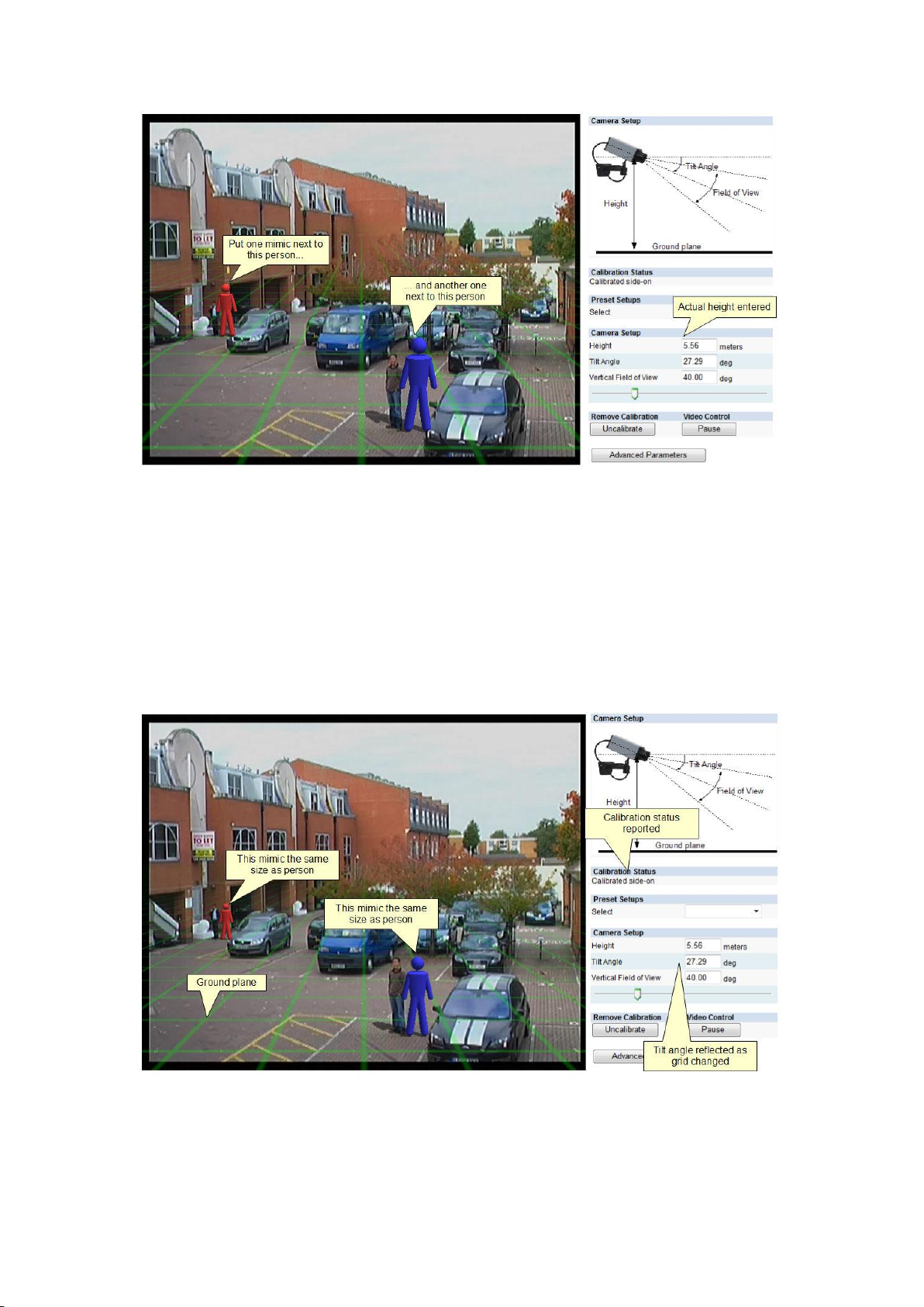
Step 1: Find some people in the scene
Find some people, or some people-sized objects in the scene. Try to find a person near the
camera, and a person further away from the camera. It is useful to use the Video Control
button to pause the video so that the mimics can be accurately placed. Place the mimics on
top of or near the people. Enter in the known height or estimated height.
62
Page 71
Camera Calibration
Step 2: Adjust tilt angle and camera height
Now, adjust the camera tilt angle and vertical field of view until both mimics are
approximately the same size as a real person at that position in the scene. If an estimated
height is entered then adjust this along with the other two parameters.
Click and drag the ground plane to change the tilt angle, use the mouse wheel to adjust the
camera height and drag the slider to change the vertical field of view.
The 3 calibration parameters will be reflected in the edit boxes in the Camera Setup section
of the web page.
Apply the changes:
Once the changes have been applied, the Calibration Status reflects whether the operation
was successful, and if so, in which mode the camera is calibrated.
Step 3: Verify the setup
63
Page 72
Printed Documentation
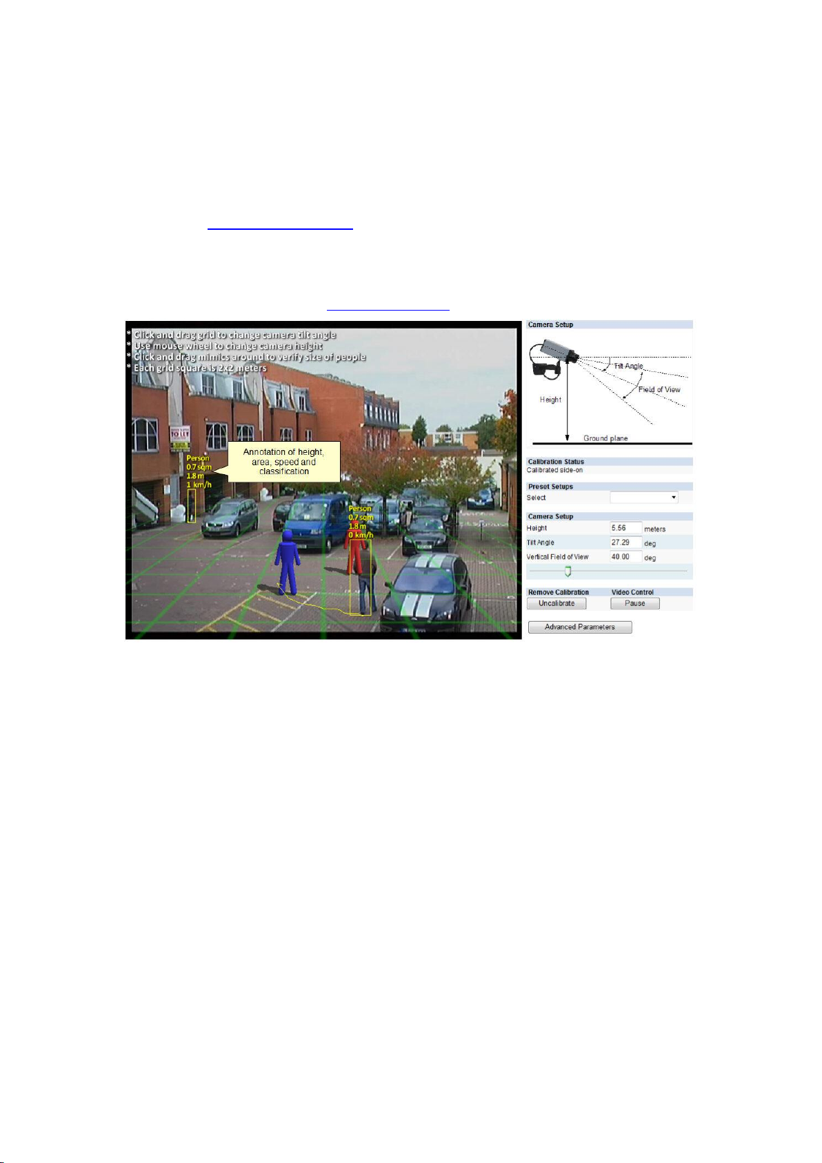
Once you are happy that the scene is correctly calibrated, verify the settings by dragging the
mimics around and comparing them to other people or people-sized objects in the scene.
The more locations in the scene where the calibration is verified, the more accurate the
calibration will be.
The 3 calibration parameters can be fine-tuned in the same way as detailed in Step 2.
Refer to the Camera Page Elements Topic for information regarding additional calibration
tools that can help improve the accuracy of the calibration.
Once the settings have been successfully applied, objects in the scene are annotated with
height, area, speed and classification. To change the measurement units between Metric
and Imperial, please refer to the Measurement Units Topic.
Tip: If it all goes wrong
If you find that the mimics get lost or disappear due to an odd calibration configuration, the
process can be restarted by clicking the "Restore Defaults" button.
Advanced Calibration Parameters
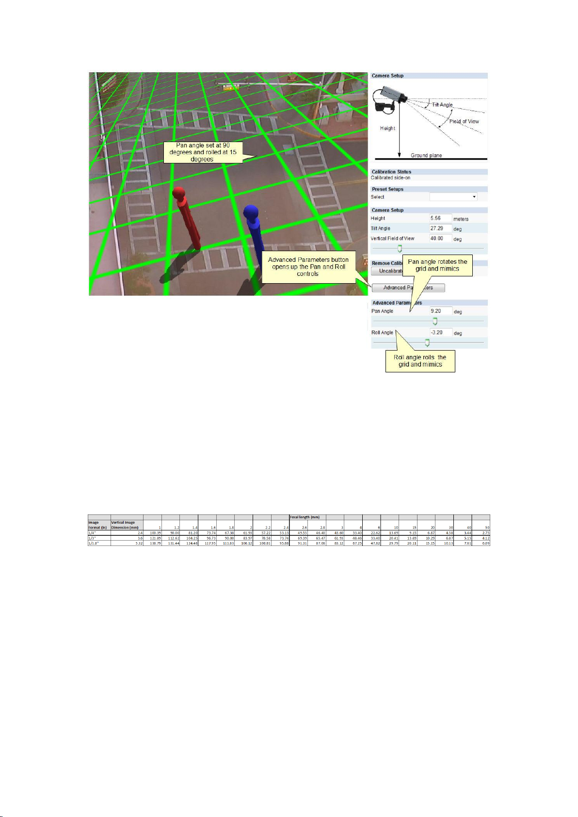
The advanced calibration parameters allow the ground plane to be panned and rolled
without affecting the camera calibration parameters. This can be useful to visualize the
calibration setup if the scene has pan or roll with respect to the camera.
Note that the pan and roll advanced parameters only affect the orientation of the 3D ground
plane so that it can be more conveniently aligned with the video scene, and does not
actually affect the calibration parameters.
To use the advanced parameters click on the advanced parameters button. Drag the pan and
roll slider controls to change the pan and roll of the ground plane.
64
Page 73
Camera Calibration
Vertical Field of View
The vertical field of view is required when calibrating a camera. If you know the vertical field
of view of the camera it can be entered directly. If however, you don't know the vertical field
of view, it can be determined from the following table, given the vertical image dimension
and its focal length:
If you are unable to determine the vertical field of view for your camera from the above
table, leave the field of view at its default setting, 40°.
Measurement Units
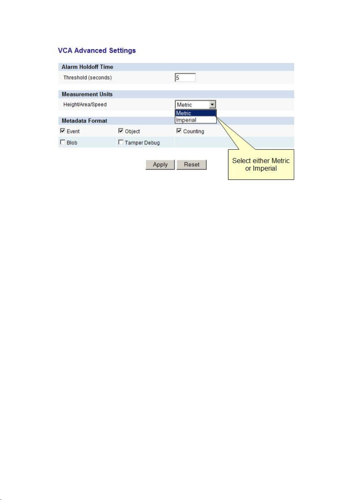
The height, area and speed annotation can be displayed in metric or imperial units. By
default the system displays metric units. To change the measurement units, select the
Advanced settings page and change the Measurement Units option. Apply the changes.
65
Page 74
Printed Documentation
66
Page 75
Object Classification
Object Classification
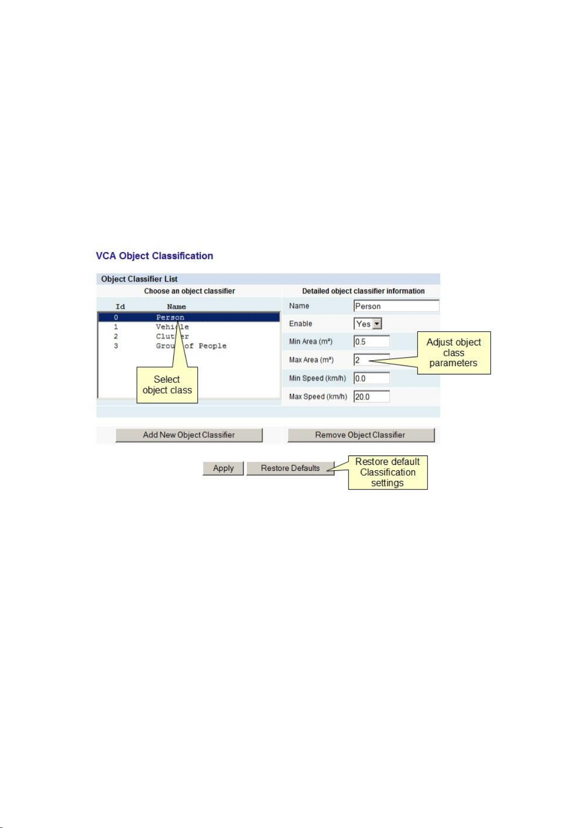
VCAsys can perform object classification once the camera has been calibrated. The object
classification is based on properties extracted from the object including object area and
speed. VCAsys comes pre-loaded with the most common object classes, and in most cases
these will not need to be modified.
In some situations it might be desirable to change the classification parameters, or add new
object classes.
To adjust the object class settings, select the Classification page and the object class to
modify:
Adjust the minimum and maximum object speed and area, and apply the changes.
Objects that do not fit into any class are labelled as "Unclassified".
67
Page 76

Page 77
Tamper Detection
Tamper Detection
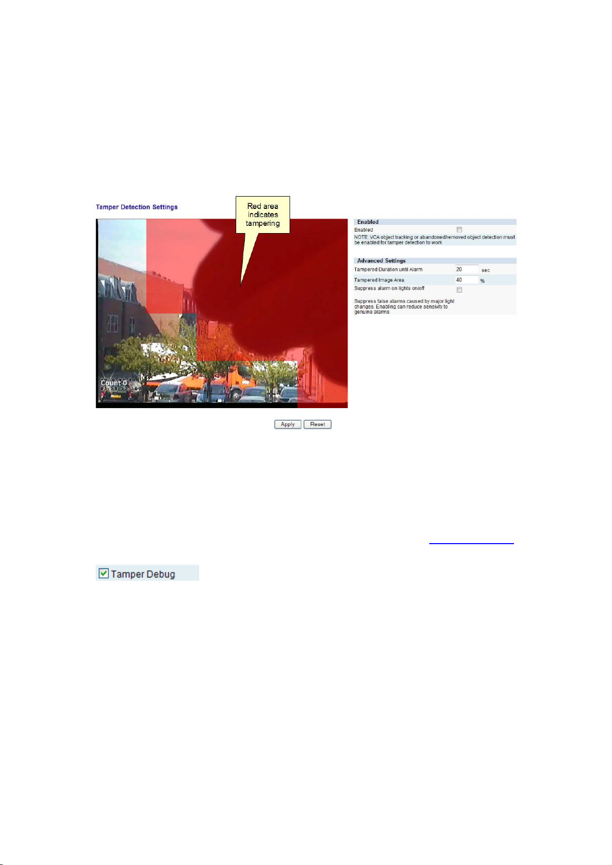
The Tamper Detection module is intended to detect camera tampering events such as
bagging, de-focusing, moving the camera, etc. This is achieved by detecting large persistent
changes in the image.
The output of the tamper detection algorithm is displayed as red blocks on the image. The
red area is where the algorithm has detected that the image has changed from its reference
image. Once enough of the image has changed and remained so for a certain length of time,
a tamper alarm is triggered.
Note: In order to see the output of the tamper detection on the image, Tamper Debug
metadata must be enabled on the VCA -> Advanced page. Please refer to Advanced Settings
for more information.
Advanced Tamper Detection Settings
In the advanced tamper detection settings it is possible to change the thresholds for the
area of the image which must be changed and the length of time it must be changed for
before the alarm is triggered.
Tampered Duration until Alarm: The length of time that the image must be
persistently changed before the alarm is triggered.
Tampered Screen Area: Percentage area of the image which must be changed for
tampering to be triggered.
If false alarms are a problem the duration and/or area should be increased so that large
transient changes such as a close object temporarily obscuring the camera do not cause false
alarms.
69
Page 78

Printed Documentation
Suppress alarm on lights on/off:
Large fast changes to the image lighting such as switching on/off indoor lighting can cause
false tamper alarms. Enable this option if this is likely to be a problem in the area where the
camera is installed. However, this option will reduce sensitivity to genuine alarms so it is not
recommended if fast light changes are not likely to be a problem
70
Page 79
Scene Change Detection
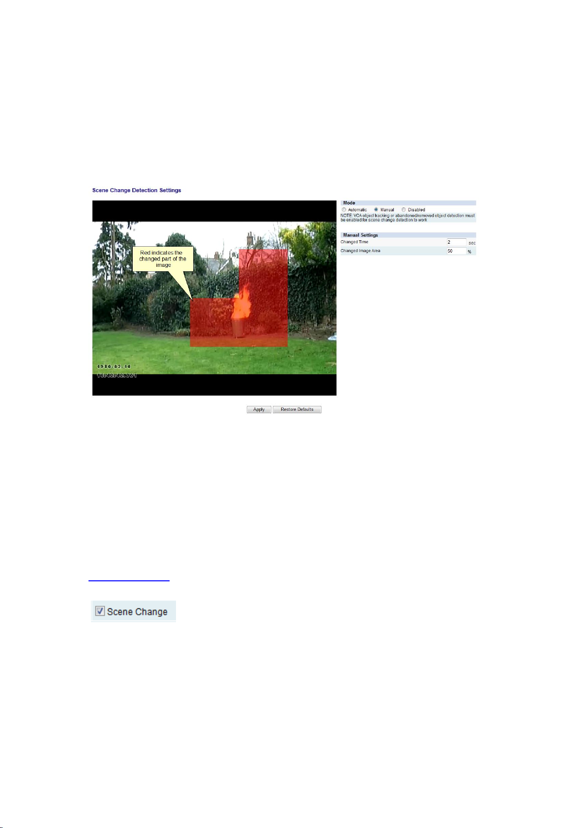
Scene Change Detection
The Scene Change Detection page allows the user to adjust the settings of the scene change
detection algorithm. The scene change detection module resets the tracking algorithm when
it detects a large persistent change in the image. This prevents the tracking algorithm from
detecting image changes as tracked objects which can be potential sources of false alarms.
There are 3 options for the scene change mode:
Automatic: Default setting. Uses the recommended settings.
Manual: Allows the user to adjust the parameters used by the scene change
detection algorithm.
Disabled: Scene change detection is disabled.
Note: In order to see the output of the scene change detection on the image, Scene Change
diagnostics metadata must be enabled on the VCA -> Advanced page. Please refer to
Advanced Settings for more information. It's only possible to see the detection diagnostic
data when in Manual mode.
Manual Scene Change Detection Settings
In the manual mode the following settings are available:
Changed Time: The length of time that the image must be persistently changed
before the scene change is triggered and the tracking algorithm is reset.
Changed Screen Area: Percentage area of the image which must be changed for the
scene change to be triggered and the tracking algorithm to be reset.
71
Page 80

Printed Documentation
If false scene change detections are a problem, the time and/or area should be increased so
that large transient changes such as a close object temporarily obscuring the camera do not
cause false scene change detections.
72
Page 81
Burnt-in Annotation
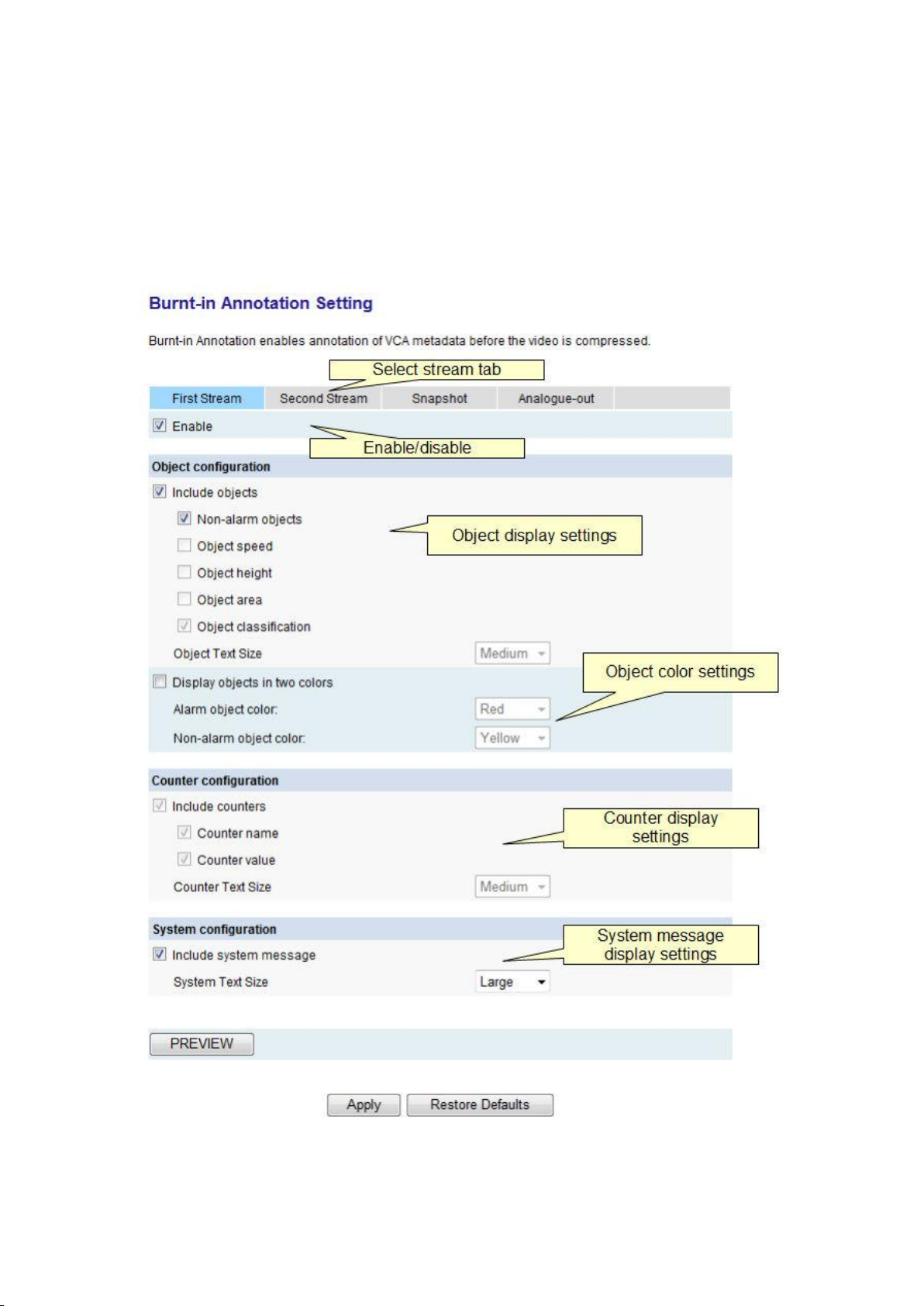
Burnt-in Annotation
The Burnt-in Annotation setting allows the VCA annotation to be burnt in to the raw video
stream. The annotation can include tracked objects, counters and system messages. The
Burnt-in Annotation can be enabled for compressed video streams or the analogue video
output, if supported.
Object Configuration
73
Page 82
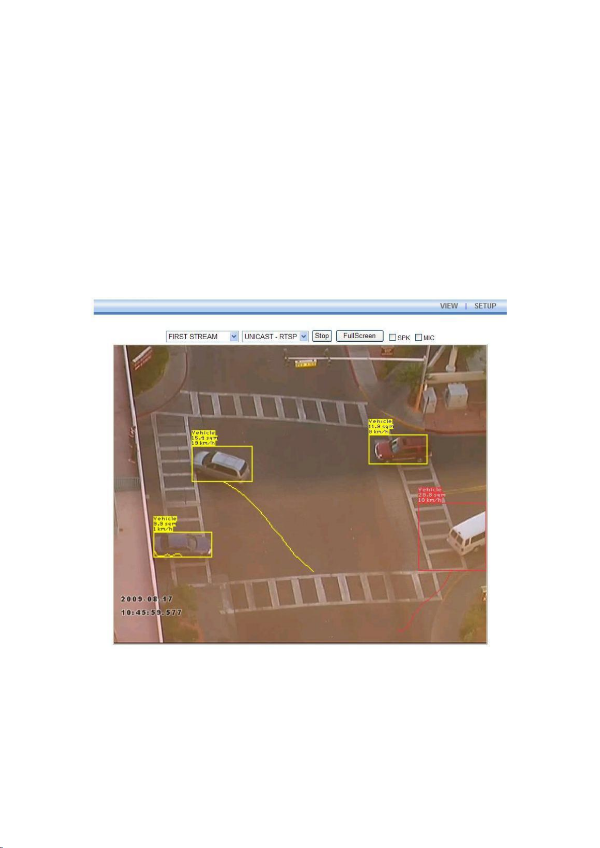
Printed Documentation
Select the object properties to display. The object text size can be changed according to the
user's preferences. Objects can be displayed in either two-color or multi-color mode. In twocolor mode, select the display colors for objects in alarm and objects not in alarm. In multicolor mode, the object colors are selected automatically by the system.
Counter Configuration
Select the counter properties to display. The counter text size can be changed according to
the user's preferences.
System Configuration
Select whether to display system messages. The system message text size can be changed
according to the user's preferences.
The following image illustrates how burnt-in annotation is applied to the video:
The different text sizes available are illustrated below:
74
Page 83
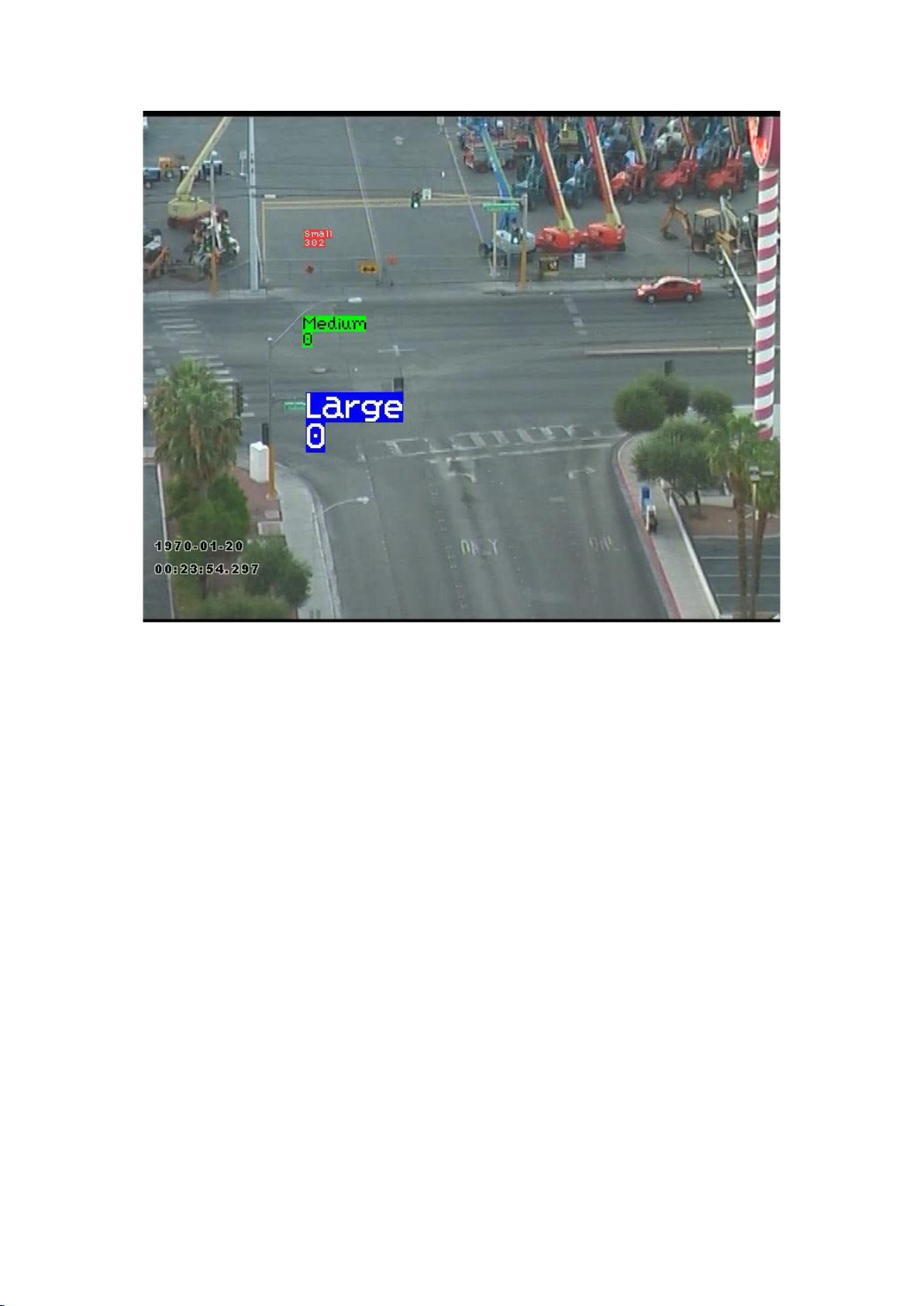
Burnt-in Annotation
75
Page 84

Page 85
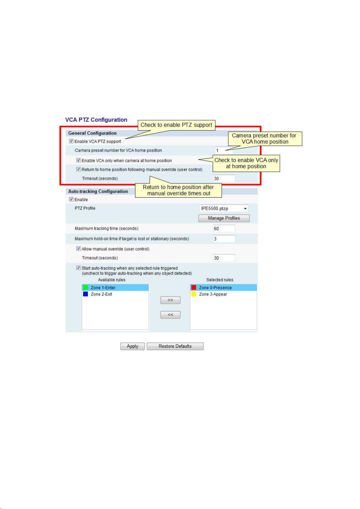
PTZ Configuration and AutoTracking
PTZ General Configuration
PTZ General Configuration allows configuration of general VCA PTZ support. This extends the
VCA functions to work with PTZ cameras. The general PTZ configuration for VCA is controlled
by the settings highlighted in the red box in the figure below.
Camera Preset Number for VCA Home Position
This text box specifies the PTZ camera preset number for VCA home position. Since the VCA
configuration is scene dependent (e.g. zone configuration is only valid when the PTZ is
pointing at the same position), the VCA can be configured such that all VCA functionality is
related to a single PTZ preset. This is the so-called "camera preset for VCA home position".
Enable VCA Only at Home Position
When checked, VCA will be only enabled when camera is at the VCA home preset position. If
the PTZ is moved by the user or any other function, the VCA is inhibited until the camera is
returned to the VCA home preset position. Note that the camera can be configured to return
to the home preset position automatically (see below).
77
Page 86
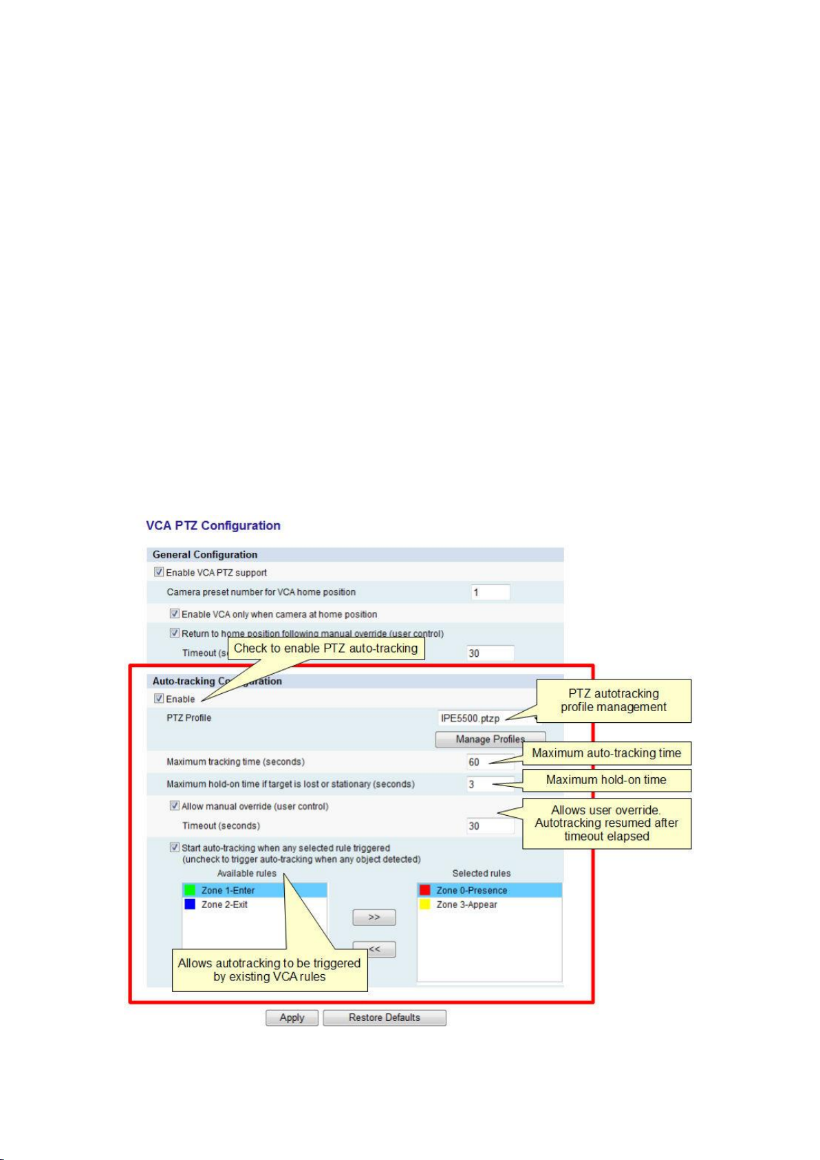
Printed Documentation
Return to Home Position Following Manual Override
When checked, the PTZ camera will automatically return to the VCA home position following
user control of the camera (manual override) after the specified timeout has elapsed.
NOTE: If this function is disabled and the VCA is enabled only at the preset home position,
VCA will not be automatically re-enabled. The only way to re-enable VCA in this mode is to
manually return the camera to the VCA home preset position.
PTZ Auto-tracking Configuration
PTZ auto tracking allows a compatible PTZ camera to track a moving subject in real-time.
When a subject is detected, the PTZ camera zooms in on the subject and moves to track it
such that it remains in view of the camera.
The PTZ auto tracking is configured by the controls highlighted in the red box in the figure
below.
78
Page 87

PTZ Configuration and AutoTracking
Maximum Tracking Time
Defines the maximum time that a subject is tracked for by the PTZ camera. Even if a subject
is being tracked by the PTZ camera, the PTZ camera will stop auto tracking (and return to
the VCA home preset position if configured) if this time elapses.
Maximum Hold-on Time
If a subject is lost by the autotracking algorithm, or comes to rest (becomes stationary), this
defines the amount of time the PTZ camera will stay in that position trying to re-acquire the
subject before returning to the VCA home preset position. If the subject starts moving again,
or is reacquired, autotracking continues until the maximum tracking time (above) elapses.
Allow Manual Override (User Control)
When manual override is enabled, the auto-tracking algorithm will release control of the PTZ
and stop controlling the PTZ camera if a user sends a manual PTZ command. The autotracking algorithm will reset when no user PTZ commands have been sent for the specified
period.
When manual override is disabled, all user PTZ commands will be ignored if auto-tracking is
in progress.
Note: In the case of autotracking, user PTZ commands refer to the PTZ commands sent
through the camera or encoder HTTP or web interface. Currently it's not possible to detect
commands sent directly on the RS-485/422/232 bus and user commands sent in this way
may cause undefined or erratic PTZ behavior if autotracking is also enabled.
Auto-tracking Initiation
PTZ autotracking can be initiated in three different ways:
Start tracking when any object is detected:
The auto-tracking will start automatically and track the first object detected by the
VCAsys tracking engine (normally from the VCA home preset position). The "Start
auto tracking when any selected rule triggered" checkbox should be unchecked to
enable this mode.
Start tracking when an existing VCA rule is triggered:
The auto-tracking will start automatically when any one of the VCA rules in the
"selected rules" list is triggered. This provides a powerful way to filter out the objects
of interest that are selected for autotracking and exclude any other objects. The
"Start auto tracking when any selected rule triggered" checkbox should be checked to
enable this mode and the rules that should initiate autotracking should be present in
the "selected rules" list on the right hand side.
Start tracking when initiated manually by the user (Manual Lay-on):
It is also possible for the user to manually initiate PTZ autotracking. This feature is
useful if the operator spots something of interest and would like the PTZ autotracking
to take over the job of tracking the subject automatically.
Manual lay-on can be achieved in two ways:
By selecting a target that is already being tracked by the VCA engine. In
this case the target will be highlighted with a bounding box on the user
display. Simply double click the target while holding the shift key and
PTZ autotracking will be initiated on the selected target.
79
Page 88
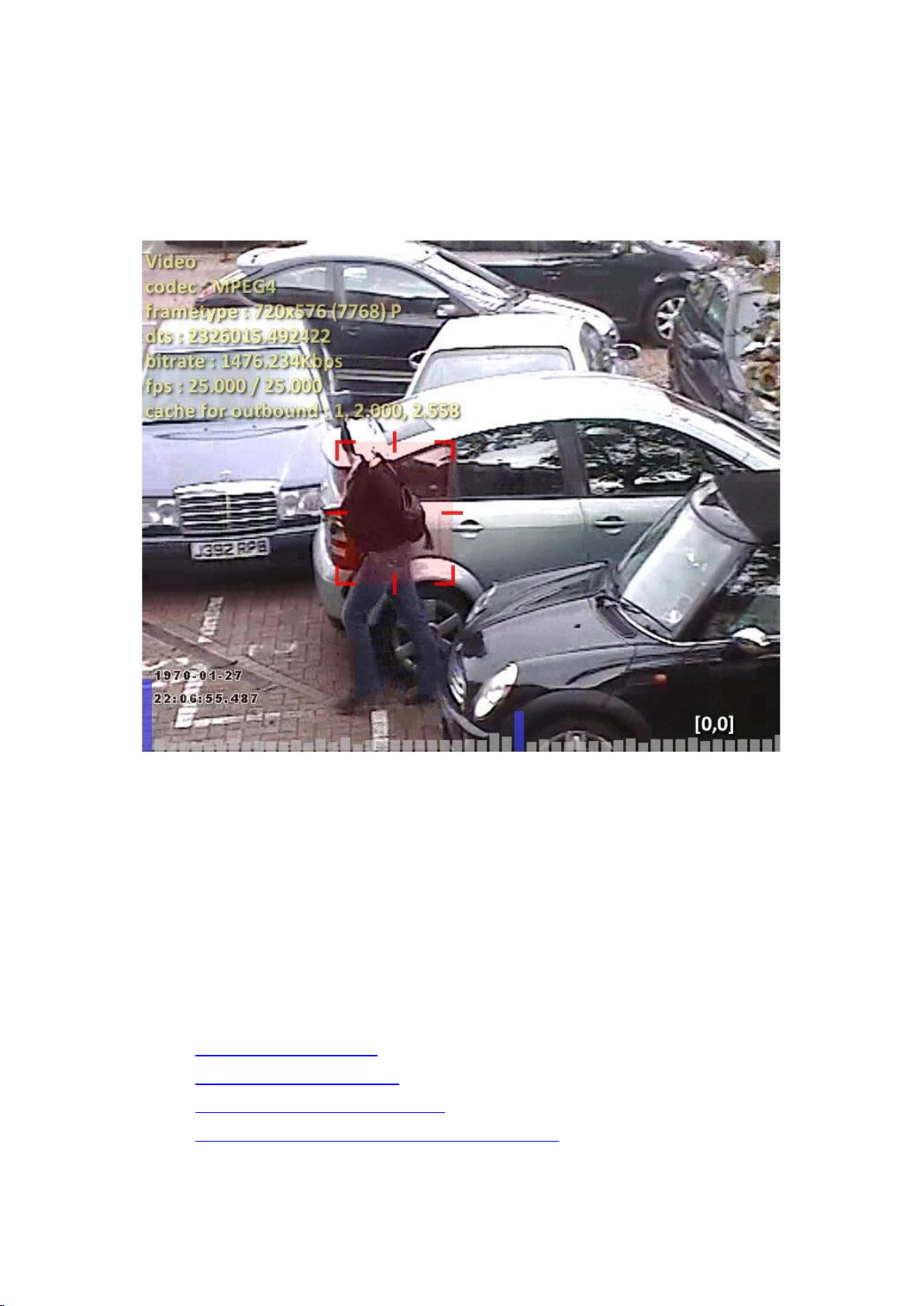
Printed Documentation
By drawing a box around any portion of the image. Simply hold the
shift key and click to drag out the target area. PTZ autotracking will be
initiated on the area indicated.
Autotracking in progress:
PTZ Profile Configuration
PTZ Profile Configuration
Since every PTZ camera has different characteristics and a different response (e.g. pan/tilt
speeds vary according to the manufacturer), this has to be accounted for by means of a PTZ
"profile". The PTZ profile is a collection of camera specific settings that define the
characteristics of a particular PTZ camera.
The device contains profiles for cameras that have already been tested, but new profiles can
be created and/or uploaded if the camera does not appear in the list of pre-tested profiles.
PTZ profile configuration consists of four main subject areas:
1. Creating a new PTZ profile
2. Editing an existing PTZ profile
3. Removing a user created PTZ profile
4. Auto-calibrating a PTZ profile for a given PTZ camera
Creating a New PTZ Profile
80
Page 89
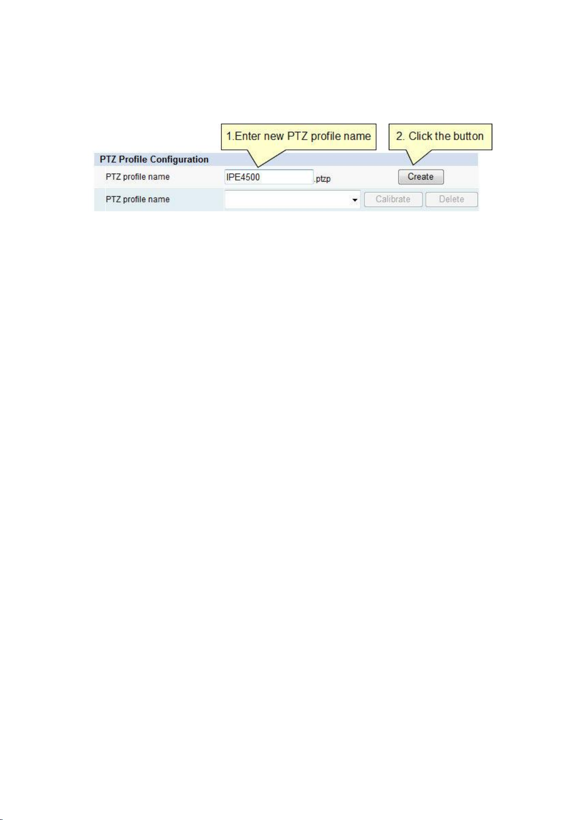
PTZ Configuration and AutoTracking
There are two steps to create a new PTZ Profile:
1. Enter the name of the new PTZ profile to be created in the text box.
2. Click the "Create" button.
The new PTZ profile will be created and stored in the list of available PTZ profiles.
Editing an Existing PTZ Profile
Note: Only PTZ profiles that have been created by the user can be edited. There are a
number of PTZ profiles that come as standard and these cannot be changed by the user.
81
Page 90
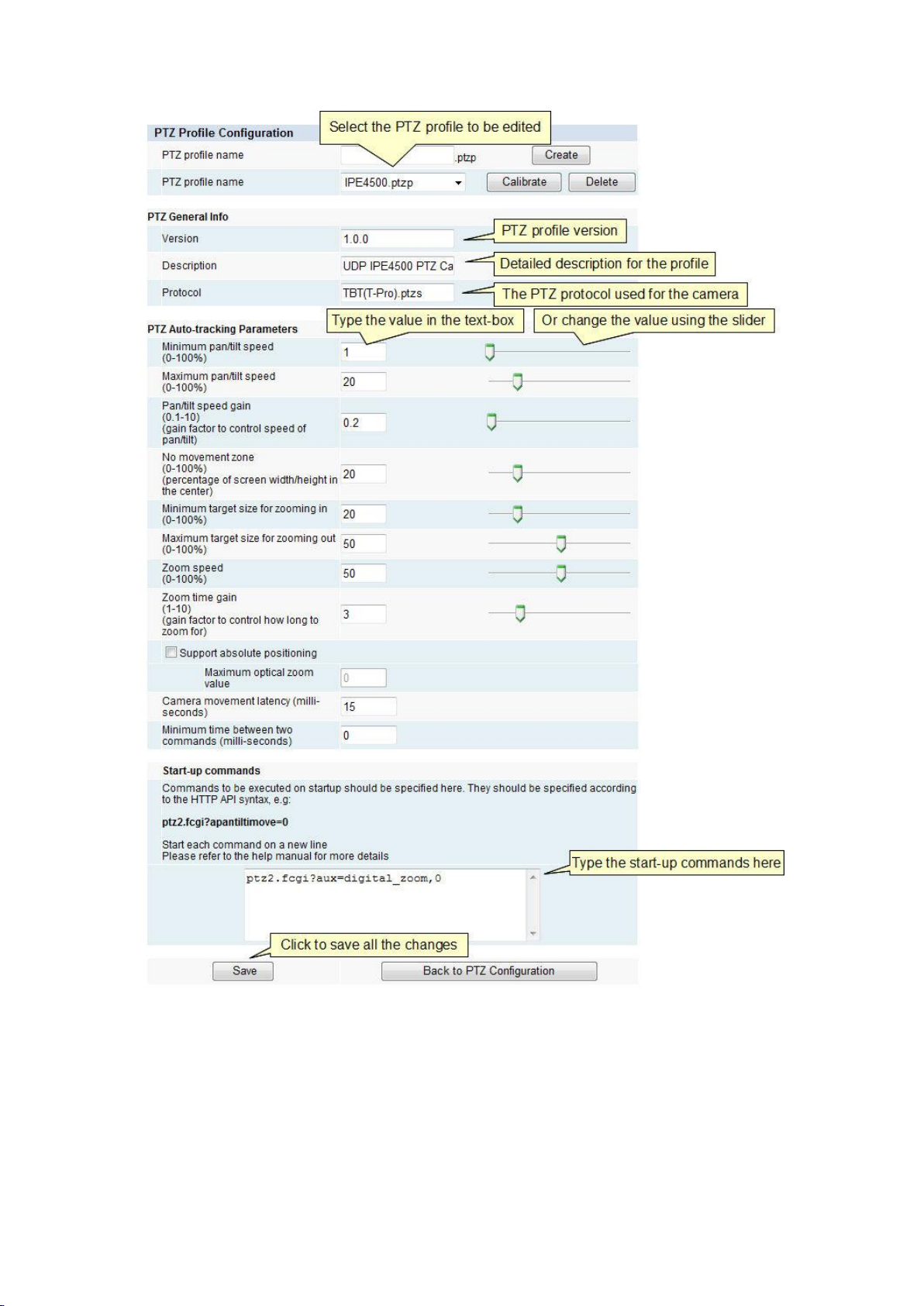
Printed Documentation
PTZ General Info
Specifies general information related to the PTZ camera profile.
Version
The PTZ profile version.
82
Page 91

PTZ Configuration and AutoTracking
Description
Detailed description for the PTZ profile, normally contains camera manufacturer and model
number.
Protocol
The PTZ protocol for the current camera. Please refer to "IO Configuration"->"UART"->"PTZ
Protocol" for all supported PTZ protocols.
PTZ Auto-tracking Parameters
Minimum pan/tilt speed
The minimum value (as specified via the HTTP API) at which the camera starts to move in
pan & tilt directions. In most cases this value will be 0 since most cameras have a linear
relationship of min->max speed over the range 0-100. However, some cameras may exhibit
non-linearities and may not start moving until they reach a pre-defined minimum threshold.
Maximum pan/tilt speed
The maximum speed that should be used by the PTZ algorithm to control the pan/tilt motors
as a percentage of the maximum speed of the PTZ camera. It should be set to correspond to
a pan/tile movement of 30°/sec when the camera is fully zoomed out.
Tip: If your camera oscillates back and forth or overshoots a target when tracking, try
reducing this value.
Pan/tilt speed gain
The gain factor to control the speed of pan/tilt. This parameter cannot be automatically
determined and needs to be determined according to the following manual process:
83
Page 92
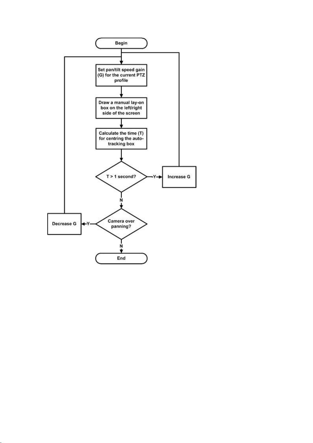
Printed Documentation
No movement (dead) zone
Percentage of screen width/height in the centre of the image where the PTZ won’t attempt
to track the subject, normalized as a percentage(0-100%). In most cases this value does not
need to be adjusted and values of between 15-20% should give satisfactory results.
Minimum target size for zooming in
Minimum target size (percentage of image width/height) to trigger the camera to zoom-in,
normalized as a percentage (0-100%). Any object size smaller than this value will cause the
camera to zoom in. The default value is 20%.
Maximum target size for zooming out
Maximum target size (percent of image width/height) to trigger the camera to zoom-out,
normalized as a percentage (0-100%). Any object size larger than this value will cause the
camera to zoom out. The default value is 50%.
84
Page 93

PTZ Configuration and AutoTracking
Zoom speed
Camera zoom speed (percentage of maximum camera zoom speed) for both zoom in and
out, normalized as a percentage (0-100%). Controls how fast the camera zooms in and out.
Where the camera only supports a fixed zoom speed, this value needs to be set to anything
other than 0. If no zooming in/out is required, set this value to 0.
Zoom time gain
Gain factor that controls how long to zoom in/out for. The default value for this parameter is
1. It is not recommended to use a value larger than 5.
Tip: If the camera zooms in too far, try decreasing this value. If it doesn't zoom far enough,
try increasing it.
Support absolute positioning
Check this box if the camera supports moving to an absolute position (e.g. P,T,Z).
From an API perspective, this box should be checked if the API command apantiltzoommove
is supported.
If the camera supports absolute positioning, then the initial target lock-on phase can be
faster since the camera moves directly to the estimated absolute position (P,T,Z) instead of
zooming in gradually.
Maximum optical zoom value
Specifies the maximum optical zoom value for the camera (e.g. 36 for a 36x optical zoom
camera). This parameter only has an effect when absolute positioning is enabled. Please
refer to the camera specification.
Camera movement latency
The time delay (in milliseconds) that it takes from issuing a PTZ command for the camera to
complete that command. The default value is 500ms.
Minimum time between two PTZ commands
The minimum time (in milliseconds) between two adjacent PTZ commands. This depends on
both the PTZ protocol and the zoom module. For example, for Pelco Spectra IV SE using
pelco-d protocol, this value needs to be larger than 300ms.
Tip: If PTZ commands appear to go missing (i.e ignored), try increasing this value.
Start-up commands
Any commands that should be executed on startup (e.g. to disable digital zoom). They
should be specified according to the HTTP API syntax for either ptz2.fcgi or serial2.fcgi.
Example: The following HTTP-API comands will perform the function (stop the PTZ camera
moving) for a camera that is configured to use the Pelco-D protocol.
ptz2.fcgi?apantiltzoommove=0,0,0
85
Page 94
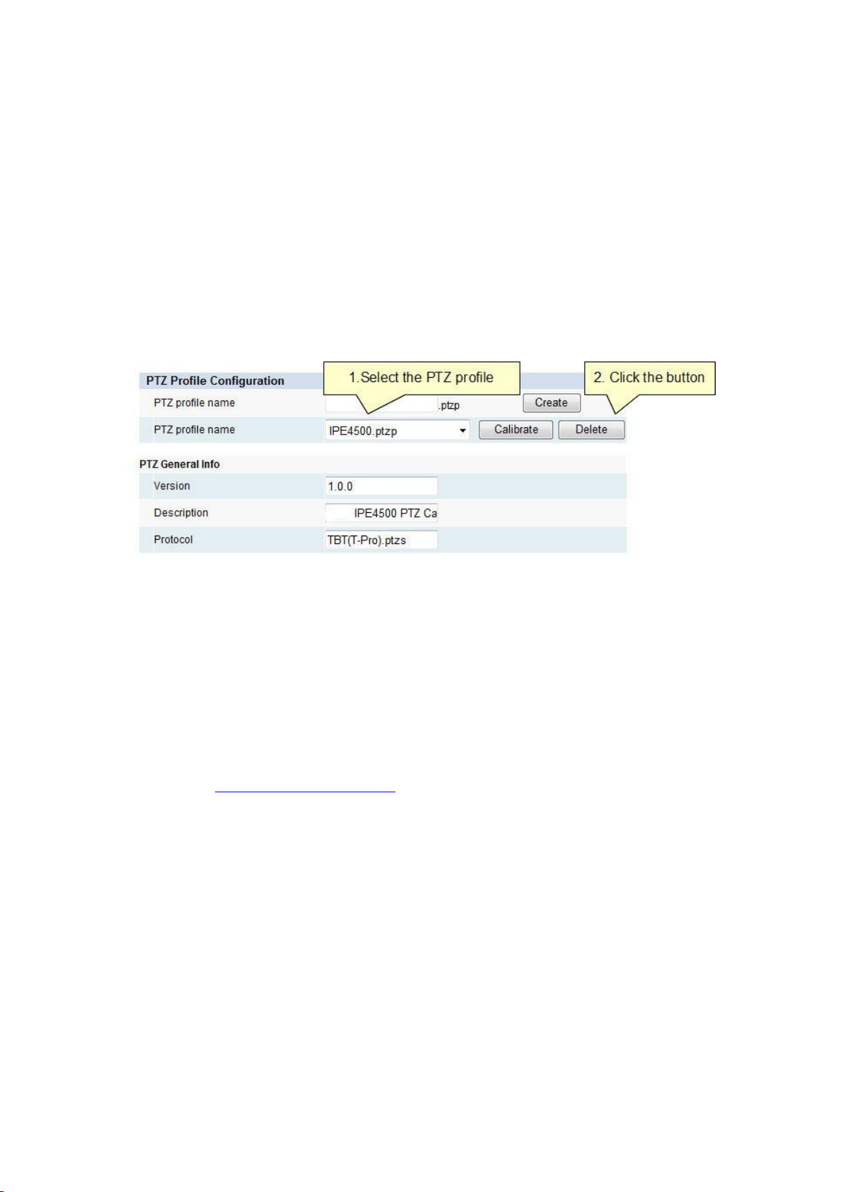
Printed Documentation
serial2.fcgi?write=ff010000000000
Removing a PTZ Profile
To remove a user created PTZ profile:
1. Select the user created PTZ profile to be deleted in the drop down box.
2. Click the "Delete" button.
Note: Only PTZ profiles that have been created by the user can be removed. There are a
number of PTZ profiles that come as standard and these cannot be changed by the user.
The PTZ profile will be deleted from the list of PTZ profiles.
Auto-calibrating a PTZ Profile
As well as being able to calibrate a PTZ camera manually, it's also possible for the device to
try and calibrate the camera automatically. Depending on the type of camera, all, some or
none of the PTZ calibration variables can be determined automatically.
Note: Whether a camera can be automatically calibrated or not is highly dependent on the
specific camera in question. In most cases, auto-calibration should be used as a starting
point to determine as many variables as possible, and then each variable should be adjusted
as necessary (see how to edit a PTZ profile).
86
Page 95
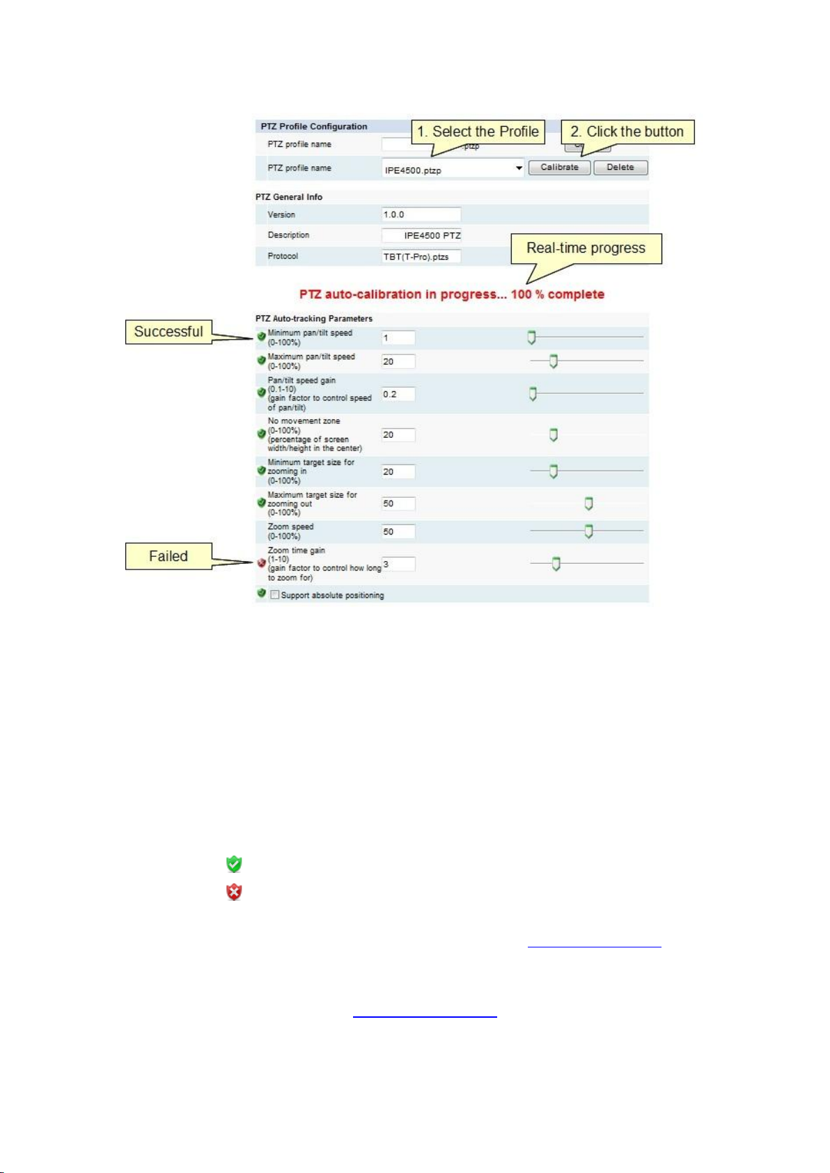
PTZ Configuration and AutoTracking
Calibrating a camera automatically
Select the PTZ profile that should be calibrated.
Click the Calibrate button to start the process.
Wait for the process to complete (can be up to 5 minutes). You should notice the
PTZ camera moving about at this point while the system tries to determine the
tracking parameters.
Once the process is complete, each parameter will be labelled as follows:
- The parameter was successfully determined.
- The parameter could not be automatically determined - manual
calibration required.
Each parameter labelled with a red cross will need to be determined manually.
Note that even after a camera has been automatically calibrated, its autotracking
performance may not be optimal. Manual determination of parameters can yield better
tracking results in some situations.
87
Page 96

Page 97
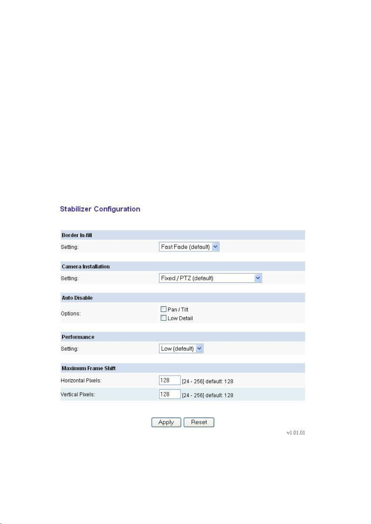
Stabilizer
Stabilizer
The video stabilizer utilizes advanced digital image stabilizing algorithms to minimise the
effects of camera shake. The stabilizer is enabled and configured using the pages under the
Stabilizer tab in the left menu. If the stabilizer functionality has been enabled by providing a
VCA Stabilizer license, the option to enable the stabilizer will appear in the Enable/Disable
page. Enabling or disabling the stabilizer will cause a few seconds pause as the system is reconfigured.
Stabilizer Configuration
When the stabilizer is enabled an additional configuration page is available under the
Stabilizer tab. The default options are suitable for most applications and you can make use
of the stabilizer functionality without modifying this page. Some installations, however, may
benefit from different configurations. The figure shows the configuration page; the
parameters are explained below.
Border In-fill
In order to keep the output frames steady and aligned to a reference frame, the output
frames are shifted with respect to the input frames. As the camera moves around, so the
89
Page 98

Printed Documentation
output frames are shifted to keep the image features aligned to previous frames. This results
in areas for which there is no image data available. The Border In-fill combo box lets you
select what happens to those areas of the image. There are 5 options available:
Fast Fade: [Default] Newer frames are composited on top of older frames. The old
frames are faded away to black quickly. This mode is most suited to PTZ and fixed
cameras.
Slow Fade: Newer frames are composited on top of older frames. The old frames are
faded away to black slowly.
No Fade: Newer frames are composited on top of older frames. The old frames are
not faded away. Suitable for fixed cameras where there is minimal movement by
people and cars around the edge of the scene.
Fixed: A fixed size black border is present on all sides which blanks out the moving
edges of the image. The size of the borders is equal to the maximum frame shift (see
below).
None: Old frames are not displayed. Regions of the output image for which there is
no available data are filled with black
Camera Installation Mode
The camera installation mode has 3 options:
Fixed/PTZ: [Default] The stabilization algorithm parameters are optimized to give
the best stabilization results for fixed/PTZ cameras.
In vehicle/Hand held: The stabilization algorithm parameters are optimized to give
the best stabilization performance for cameras where the camera fixture
experiences continued, large displacements or scene changes. E.g. when shot from a
moving vehicle.
Low Frequency Stabilization: The Fixed/PTZ and In vehicle/hand held stabilization
modes are designed to allow tracking of intentional camera panning by not
stabilizing low frequency movements (< 1Hz). The Low Frequency mode has a lower
cut-off frequency to allow better low frequency stabilization at the expense of worse
tracking of intentional movement. This mode will automatically switch to the higher
frequency mode when excessive movement in one direction is detected in order to
allow better tracking of intentional movement. Once this movement has stopped it
will revert back to the low frequency mode.
Auto Disable
There are 2 options for Auto Disable - neither is selected by default:
Pan/Tilt: This option disables the stabilization when excessive pan or tilt motion is
detected. This makes it easier to control pan/tilt cameras because the Stabilizer
ceases to oppose operator pan/tilt commands above the threshold. Once panning
stops, there is a 3 second timeout period before stabilization is reactivated.
90
Page 99

Stabilizer
Low Detail: When this option is enabled, the algorithm is disabled when a scene
with insufficient detail for reliable stabilization is detected. This prevents the image
position 'hunting’ when there is very little scene detail or features. For example,
when the camera is pointed at a completely blank wall the stabilized image will jump
around slightly because it is locking on to the random video noise. Similar hunting
problems can occur in other situations where a large part of the scene lacks suitable
detail for Stabilizer lock.
Performance
Performance setting of the algorithm. Better stabilization performance comes at the
expense of higher DSP load. The default setting is low.
Maximum Frame Shift
This is the maximum amount in image pixels that the algorithm will shift the frame
horizontally and vertically in either direction from the normal position. Both horizontal and
vertical shifts are configurable in the range [24 - 256], the default is 128.
91
Page 100

 Loading...