

Ganz NR16H-12TB User Manual
A
1

CONTENT
OVERVIEW PLAYBACK
3 Before Installation 75-77 If you want to play
4 Key Features
6 Front Panel
7-8 Rear Panel
9-10 Remote Control At a Glance
INSTALLATION ARCHIVING
11-14 HDD Replacement
15 Basic Layout 78-80 To start the Archive menu
16-25 Connecting to an external devices
26 Camera Installation mode
MONITORING WEB VIEWER
27-28 Start up/Shutdown 87 What is the Web Viewer?
29-37 Live Screen at a Glan 83-86 Live
87-88 Search
89-100 Setup
SYSTEM SETTING MOBILE VIEWER
38 To move to the System Setup menu 101-111 GanzView
39-41 Camera Setting
42-44 PTZ Setting / Display Setting
45 Audio Setup
46-47 User Setting
48-51 Network Setup
52-55 System Setting
56-58 Storage
58-64 Event Setup
RECORD SETTING ARCHIVE VIEWER
65 To start the Record Setup menu 112 Getting started with the Backup
Play
66-69 Record Setup 113-115 Backup Player at a Glance
70 Network Streaming
SEARCH APPENDIX
71-74 To move to the Search menu while 116-117 Specification
in monitoring / in playback mode
2

OVERVIEW
The Company shall not have any responsibility for any accident or damage that may
incur during the use of the product.
For your safety, we provide a few instructions about installation, manipulation,
cleaning, assembly/disassembly of the product as below. So please read carefully
and comply with the instructions.
Before installation
Comply with the following instructions to prevent a fire, explosion, system failure shock. or
electric
Remove the power supply module before proceeding.
Check the input voltage (AC100V–AC240V) to the power supply module before
connecting it.
Keep the product away from humidity.
Ensure that all devices connected to the product should be properly earth-grounded.
In operation mode
Comply with the following instructions to prevent a fire, explosion, system failure or electric
If you need to open the cover, consult with a service person who could help you do
what you want to do.
Do not connect multiple devices to a single power socket.
Keep the product away from dust or too much combustible substances (ex: propane gas).
Do not touch it with wet hand.
Do not insert a conductor in the vent of the ventilation system.
Do not apply excessive force to unplug the power cord.
Disassembly & Cleaning
When cleaning on the surface, use a dry cloth.
Do not wipe the product using water, paint thinner or organic solvents.
Do never dismantle, repair or modify the product by your own.
During installation
To prevent an accident or physical injury and to operate NVR properly, please comply with
the followings
Secure at least 18 centimeter of distance between cooling fan and wall for a proper
ventilation.
Install the product on a flat surface.
Keep it away from direct sunlight or excessive temperature.
While in use
Do not apply force to or shake it while using it.
Do not move, throw away or put excessive force to it.
Using any un-recommended HDD may cause a system failure. Check the compatibility
list and use only compatible HDDs.
{A system failure or data loss caused by an incompatible HDD will void your warranty.}
3

OVERVIEW
Key Features
This product allows you to receive audio and video signals from a max of 4/8/16 CH 1080p
H.264 network camera before saving them to the internal HDD.
Besides, you can also transfer them to an external device that can be monitored on your PC
or mobile phone remotely.
Display the video from up to 4/8/16 CH 1080p network camera in real time
(Max 120/240 fps)
Save the video from up to 4/8/16 CH 1080p network camera in a max of 32/64Mbps
(8Mbps per channel) (Max 120/240/480fps)
Play up to 4/8/16 CH 1080p video in real time (Max 120/240/480fps)
H.264 BP/MP/HP network camera supported(BP: Baseline profile, MP: Main profile,
HP: High profile)
4/8 built-in port, PoE switching hub (40W/72W)
‘Plug & Play’ camera connection
Protect the IP camera via secured closed circuit LAN environment
Auto notification with self diagnosis (HDD S.M.A.R.T, temperature, network connection
status, fan error, etc.)
Dual streaming supported for a remote display
Auto resolution & FPS adjustment for a remote service
External eSATA HDD supported – various search methods (time, event, bookmark
and thumbnail)
Mass storage backup via USB port or FTP server
Dedicated smart phone applications that can be used with iPhone and iPad or on
Android OS
1080p Full HD GUI
4
OVERVIEW
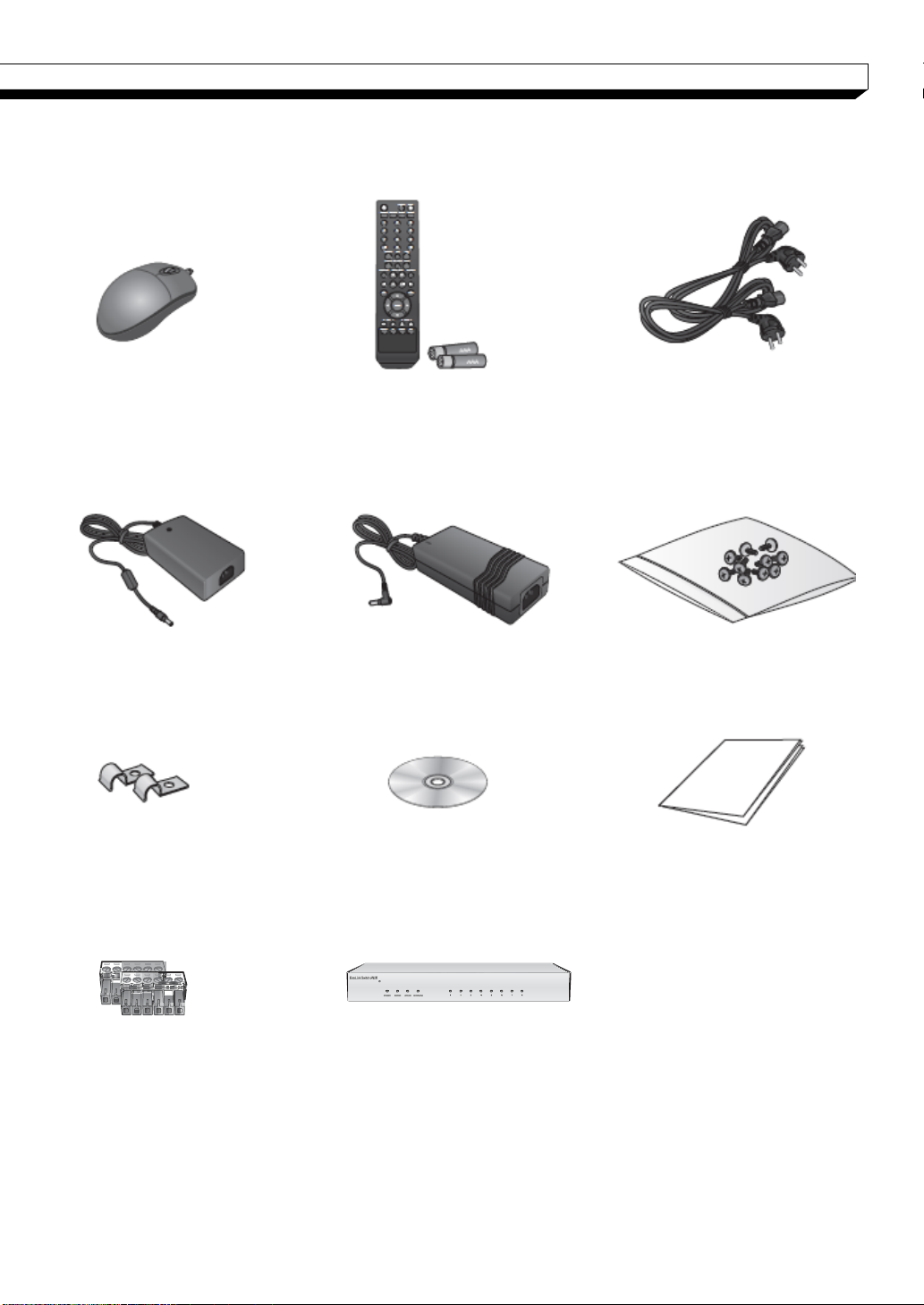
What's included
Mouse Remote Control x1 Power Cable x2
& Batteries (AAA x2) (Provide only 1 for NR8H)
DC 12V Adaptor DC 48V Adaptor Screws
(NR4HL/NR8HL only) (Except NR8H)
Adapter cable retainer clip x2 User manual CD Quick User Guide
(NR4HL/NR8HL only)
Terminal Blocks x2 8-channel Extension Hub x1
(NR16H only)
5

OVERVIEW
Name
Description
IR Remote
Control
Receiver
Receive the signal from the remote control
USB
Used for connecting USB storage or mouse.
Status LED
Show the status of power, recording or network connec
tion together with the corresponding alarm.
Name
Description
IR Remote
Control
Receiver
Receive the signal from the remote control
USB
Used for connecting USB storage or mouse.
Status LED
Show the status of power, recording or network connec
tion together with the corresponding alarm.
HDD 1~5 /
eSATA
HDD1 HDD2 HDD3 HDD4 HDD5 eSATA
Indicates connection status of internal/external storage
devices.
Front Panel
| NR4HL / NR8HL
| NR8H / NR16H
6
OVERVIEW
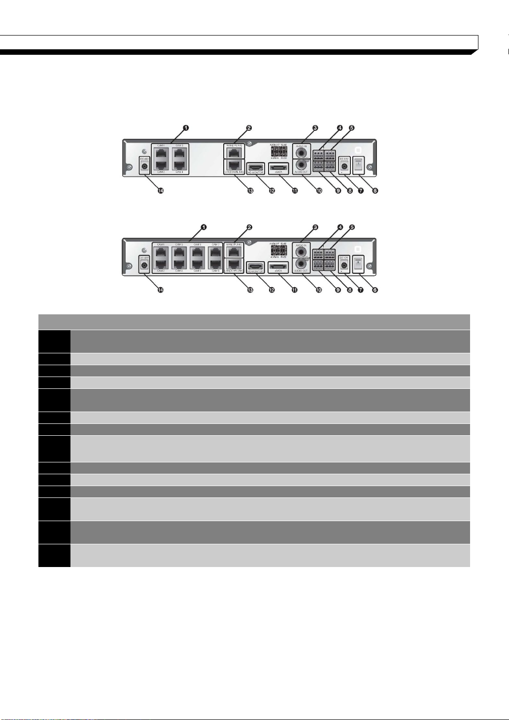
NO Name
Description
1
CAM1~CAM8
Ethernet ports used for connecting the network camera video
and power.
2
WAN(UPLINK)
Network port for connection to the Internet, router or hub
3
AUDIO IN
Microphone connection port.
4
ALARM OUT
Alarm output device connection port.
5
RS-485
Communications port for connecting peripherals such as system
keyboard.
6
Power Switch
NVR power switch. Plug the power cord and turn this switch on.
7
DC 12V
NVR power input port Connect to a 12V adaptor.
8
RS-232C
Signal connection port for POS and ATM.-Scheduled to be
upgraded.
9
ALARM IN
Alarm input signal port.
10
AUDIO OUT
Port for speaker connection.
11
eSATA
Connection port for external SATA storage.
12
HD MONITOR
Port for connecting a full HD(1920x1080) supported monitor.
Use the HDMI cable to connect with a 1080p 60Hz monitor.
13
LAN(DOWNLIN
K)
Port for connecting the dedicated network device. (Do not share
with other device.)
14
DC 48V
Power input port for the camera (PoE compliant).
Connect to a 48V adaptor.
| NR4HL
| NR8HL
Rear Panel
7
OVERVIEW
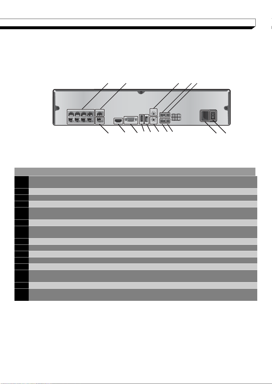
NO Name
Description
1
CAM1~CAM8
Ethernet ports used for connecting the network camera video and
power. (Can supply power to cameras with PoE function)
2
WAN(UPLINK)
Network port for connection to the Internet, router or hub
3
AUDIO IN
Microphone connection port.
4
ALARM OUT
Alarm output device connection port.
5
RS-485
Communications port for connecting peripherals such as system
keyboard.
6
Power Switch
NVR power switch. Plug the power cord and turn this switch on.
7
100-240V 50/60 H
z
NVR power input port.
8
RS-232C
Signal connection port for POS and ATM. (TBA)
9
ALARM IN
Alarm input signal port.
10
AUDIO OUT
Port for speaker connection.
11
USB
Port for connecting USB devices. (For mouse or firmware updating)
12
eSATA
Connection port for external SATA storage.
13
HD MONITOR
Port for connecting a full HD(1920x1080) supported monitor.
Use the HDMI cable to connect with a 1080p 60Hz monitor.
14
VGA
VGA video output terminal. (TBA)
15
LAN(DOWNLINK)
Port for connecting the dedicated network device.
(Do not share with other device.)
| NR8H / NR16H
Rear Panel
| 8H / 16H
1 2 3 4 5
15 13 14121110 9 8 7 6
8
OVERVIEW
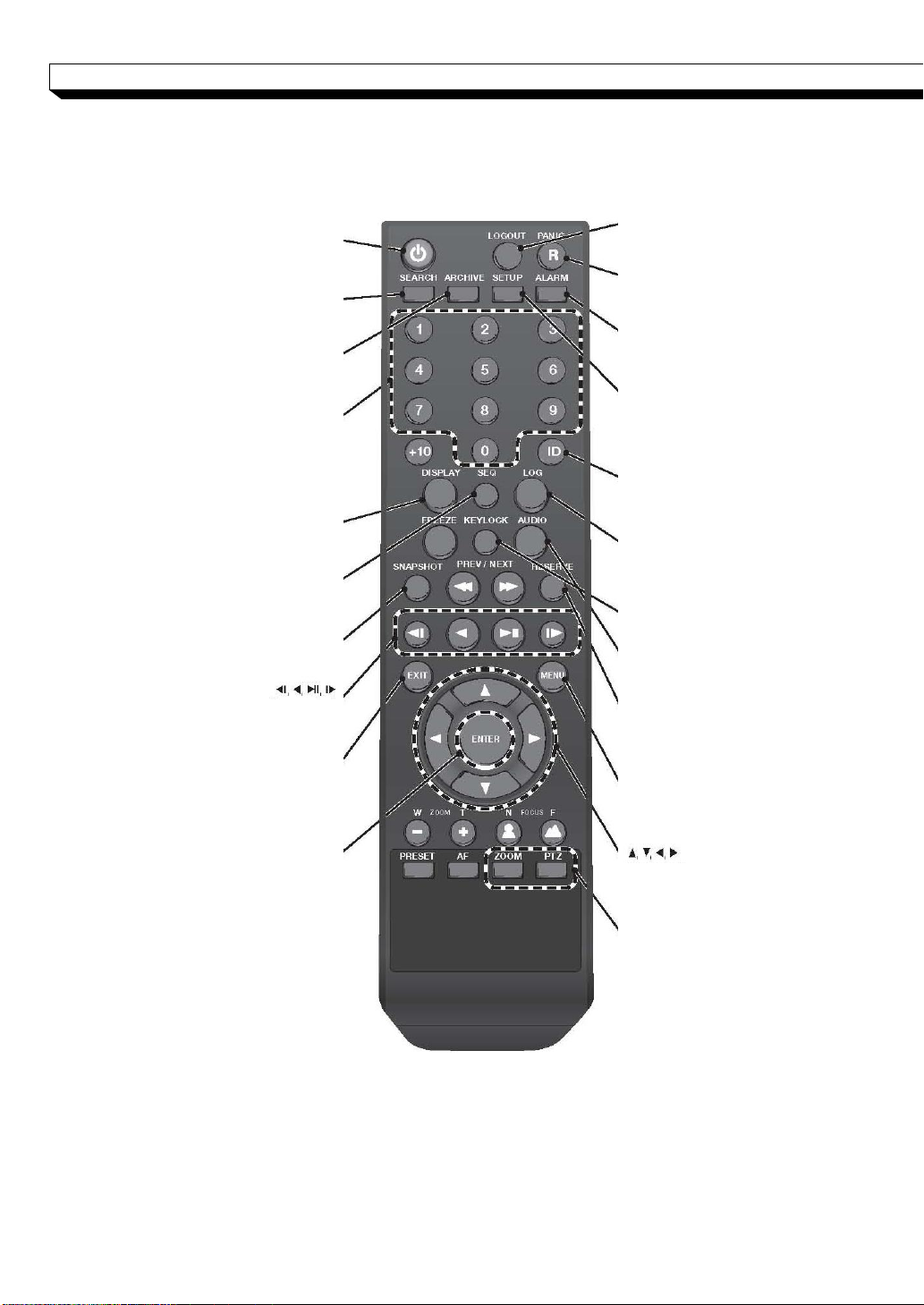
LOGOUT
LOGOUT
POWER
Turn on or off the power.
PANIC
Start the emergency recording.
SEARCH
Display the search window.
ALARM
Show the alarm status with
a popup window.
ARCHIVE
Display the backup window.
SETUP
Display the system setup menu.
Channel
Function as channel selection
button in live or playback mode.
Or used for entering the password.
ID
Set the remote control ID.
DISPLAY
Switch the split mode.
SEQ
Switch to sequence mode.
SNAPSHOT
Turn on or off the power.
Used to change the direction
or adjust the play speed
in playback mode.
EXIT
Exit from the current screen
and return to the previous
screen.
ENTER
Select a menu item or
apply your settings.
LOG
Display the log list.
KEYLOCK
Lock any operation on the unit.
AUDIO
Display the audio channel
selection window.
RESERVE
Turn on or off the power.
MENU
Display the tool bar on the live
screen.
Use to move through the menus
PTZ/ZOOM
Enter the PTZ or digital zoom
Mode and control the operation.
Remote Control At a Glance
9

OVERVIEW
Change the remote control ID
The remote control will be active only if the remote control ID matches with that specified on
the NVR.
If multiple NVRs are installed on one place and you have just a single remote control, use
the ID button to set the remote control ID. Only the ID-matching NVR can be controlled.
1. From <SYSTEM> - <CONTROL DEVICE> under the System Setup menu, set the
<REMOTE CONTROLLER ID> and press <Apply>.
Select between 00 and 99. For more details, refer to <SYSTEM SETUP>.
The remote control will be active only if the remote control ID matches with that of
the NVR's system ID.
2. Press the [ID] button on the remote control. The default remote control ID is 00.
3. Use the number buttons to provide a two-digit ID. If you want to enter 01, for
instance, enter the number 0 and 1 in sequence.
Check if the remote control ID is set properly by manipulating the remote control.
4. To reset the ID to 00, press and hold the [ID] button.
10
INSTALLATION
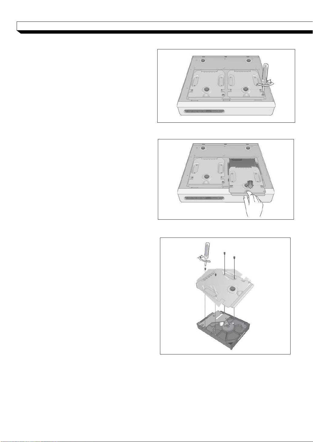
NR4HL/8HL
1.
Remove the bracket screw
on the bottom of the NVR.
2.
Hold the bracket handle in the middle
and pull it out to separate the bracket
form the main unit.
3.
Install the HDD on the separater bracket
and fasten 4 screws on both sides to
secure HDD.
When installing HDD, make sure to
install in the correct direction.
11
INSTALLATION
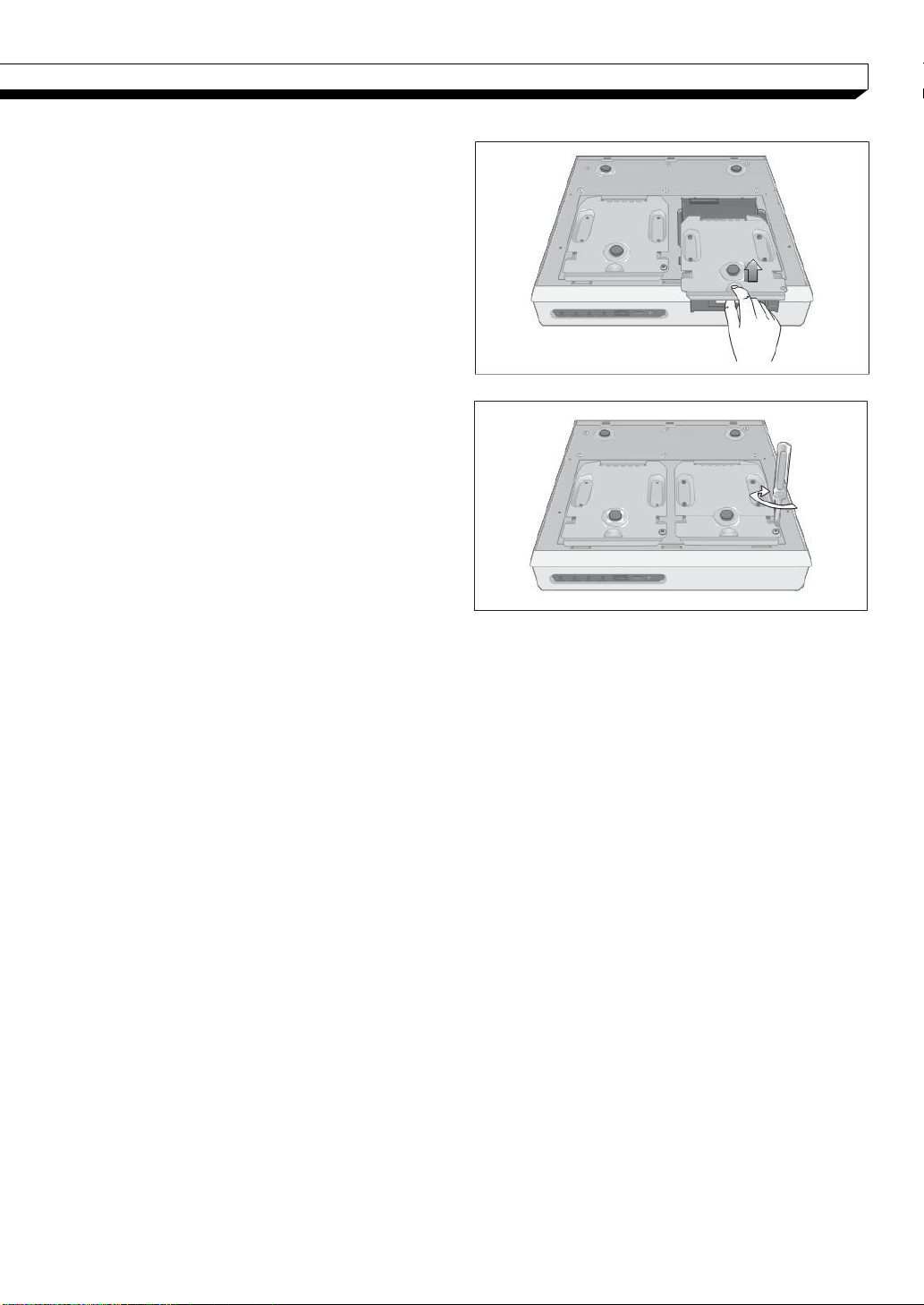
4.
Insert the bracket instead with HDD back
into the main unit.
5. Fasten the bracket screw removed earlier.
12
INSTALLATION
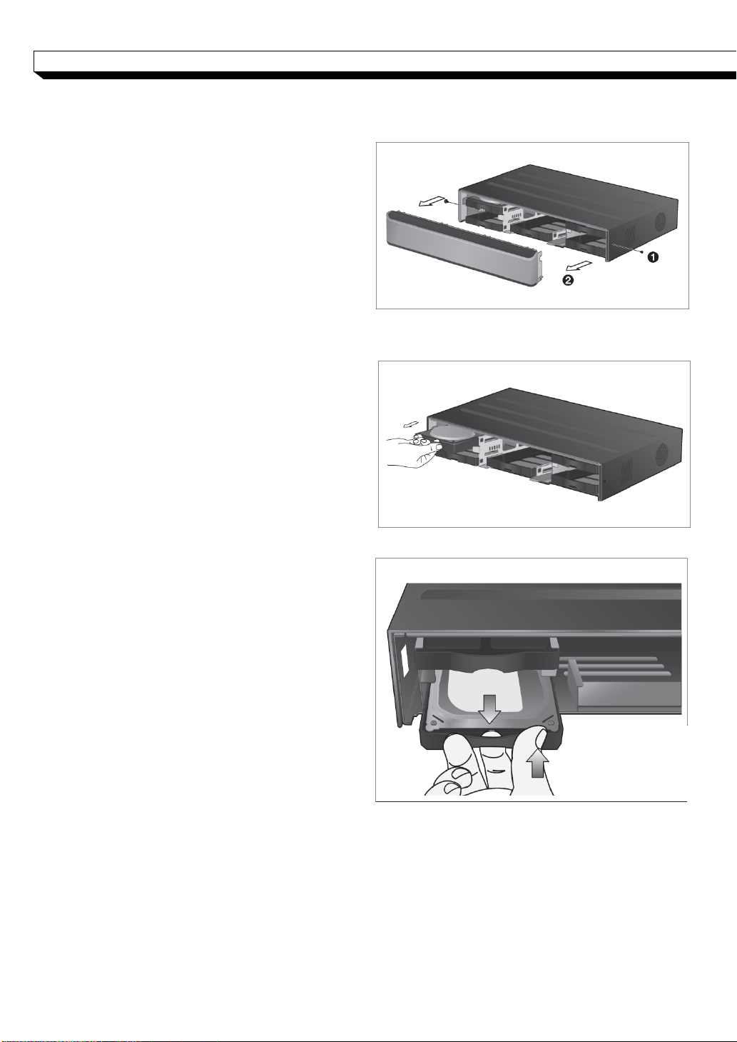
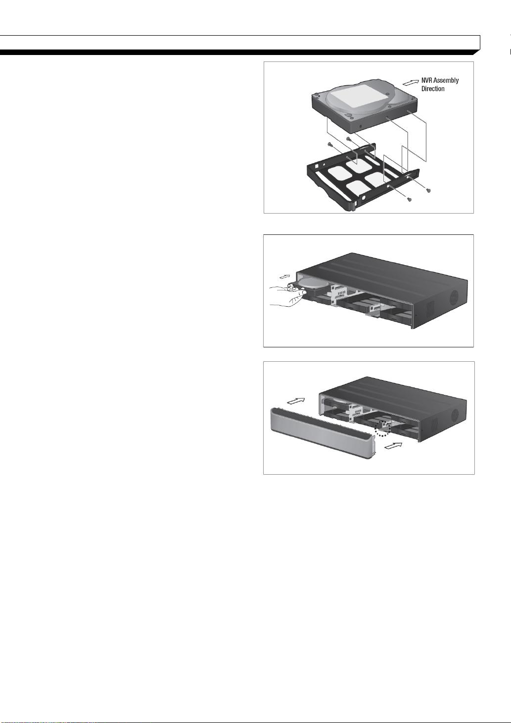
NR8H/16H
1. Remove 2 screws on both ends of NVR.
2. Pull the front side of the unit forward to
separate it.
3. Hold the middle of the HDD brackets
handle with index finger and pull it toward
while sustaining the bracket handle with
your thumb and middle finger as shown
in the illustration.
13
INSTALLATION
4. Once the HDD bracket is separated from
the main unit, remove 4 screws on both
ends of HDD bracket to separate the
HDD.
5. Install a new HDD and fasten 4 screws
back to both ends of the bracket to fix.
When installing HDD, make sure to
Install in the correct direction.
6. Push the bracket installed with new HDD
back into the main units it is completely
inserted.
7. Assemble the front panel back to the
unit.
When assembling the front panel to
the main unit, make sure the marked
part is tightly attached.
8. Fasten 2 screws on both ends of main
unit.
14
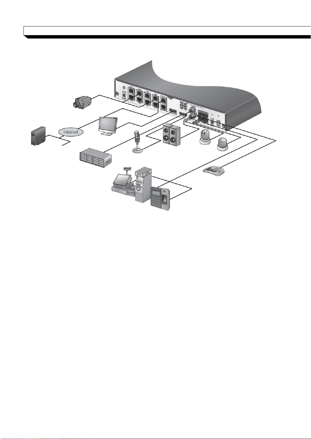
Camera
Network
Attached
Storage
CMS
Web viewer
Mobile viewer
Full HD
monitor
eSATA
Storage
Speaker
MIC
Sensor
Alarm
Control
Device
POS
Access
Controller
INSTALLATION
Basic Layout
Precautions
To secure recording stability from an overloaded network traffic , hacking attempt or DoS
(Denial of Service) attack, only the direct cable connection between camera and NVR is
allowed.
Using a hub is allowed only for extending single channel for extended transfer range
to 100m each.
Any access from an outside PC to the IP camera will be strictly prohibited for the purpose
of secure operation.
Signal connection for POS and ATM is scheduled to be upgraded later.
15
INSTALLATION
DC48V adaptor
DC12V adaptor
Adaptor cable
retainer clip
Connecting to an external device
Connecting to the monitor
This product supports VGA (D-sub) monitors that support resolution of 1080p 60Hz HDMI or
1920x1080.
Connct the product with HDMI cable by connecting it to HDMI Out port under the unit and H
DMI Input port of the monitor.
Or, use a HDMI-to-DVI cable by connecting the product’s HDMI port and the monitor’s DVI
port. You can use a VGA (D-sub) cable to connect this product and VGA port of the monitor.
! Output for two monitors at the same time is not supported.
Either one of the HDMI and VGA output to one monitor is available.
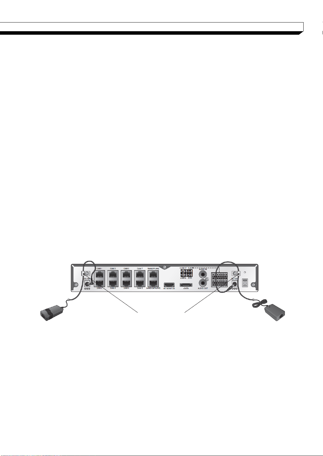
Power Connection
- NR4HL /NR8HL
Two adaptors are provided: one for NVR operation (DC 12V), and the other for PoE (Power
Over Ethernet, DC48V).
NVR power connection
Plug the provided DC 12V adaptor in the rear power port of the NVR.
PoE Switching hub power connection
Plug the provided DC 48V adaptor in the rear power port of the NVR.
When done, attach the adaptor cable clip to the rear panel and insert the cable in.
16
INSTALLATION
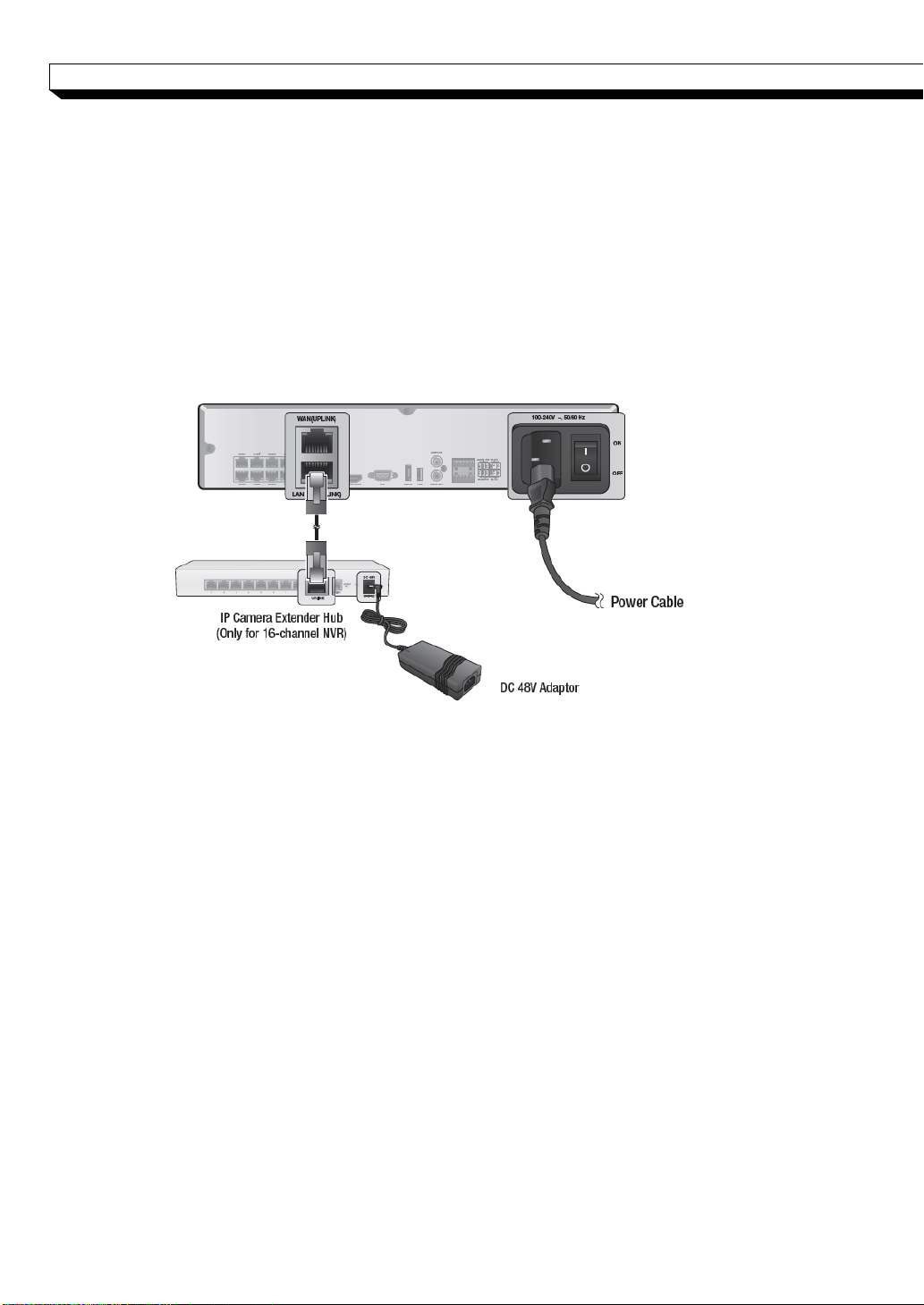
- NR8H /NR16H
Apply power to NVR main unit, and connect the provided DC 48V power supply adaptor to
the external PoE switch (Power Over Ethernet for 16-channel models).
NVR power connection
Connect the provided power cord to the power inlet.
PoE Switching hub power connection
Plug the provided DC 48V adaptor in the rear power port of the Hub.
Make connection when the power is not applied yet.
Arrange up the cables and be careful not to peel off the cable coating.
Do not place the power cord under the carpet or rug. The power cord is usually
earth-grounded. However, even
if it's not earth-grounded, do never modify it on your own for earth-grounding.
Do not insert multiple devices in a single power socket. Otherwise, it may cause a
power overload.
For stable power supply, this product provides two separate adaptors and two
corresponding AC cords by factory default. Make sure all cables are connected
properly.
Make sure the power connection and cable are connected tightly and not loose.
17
INSTALLATION
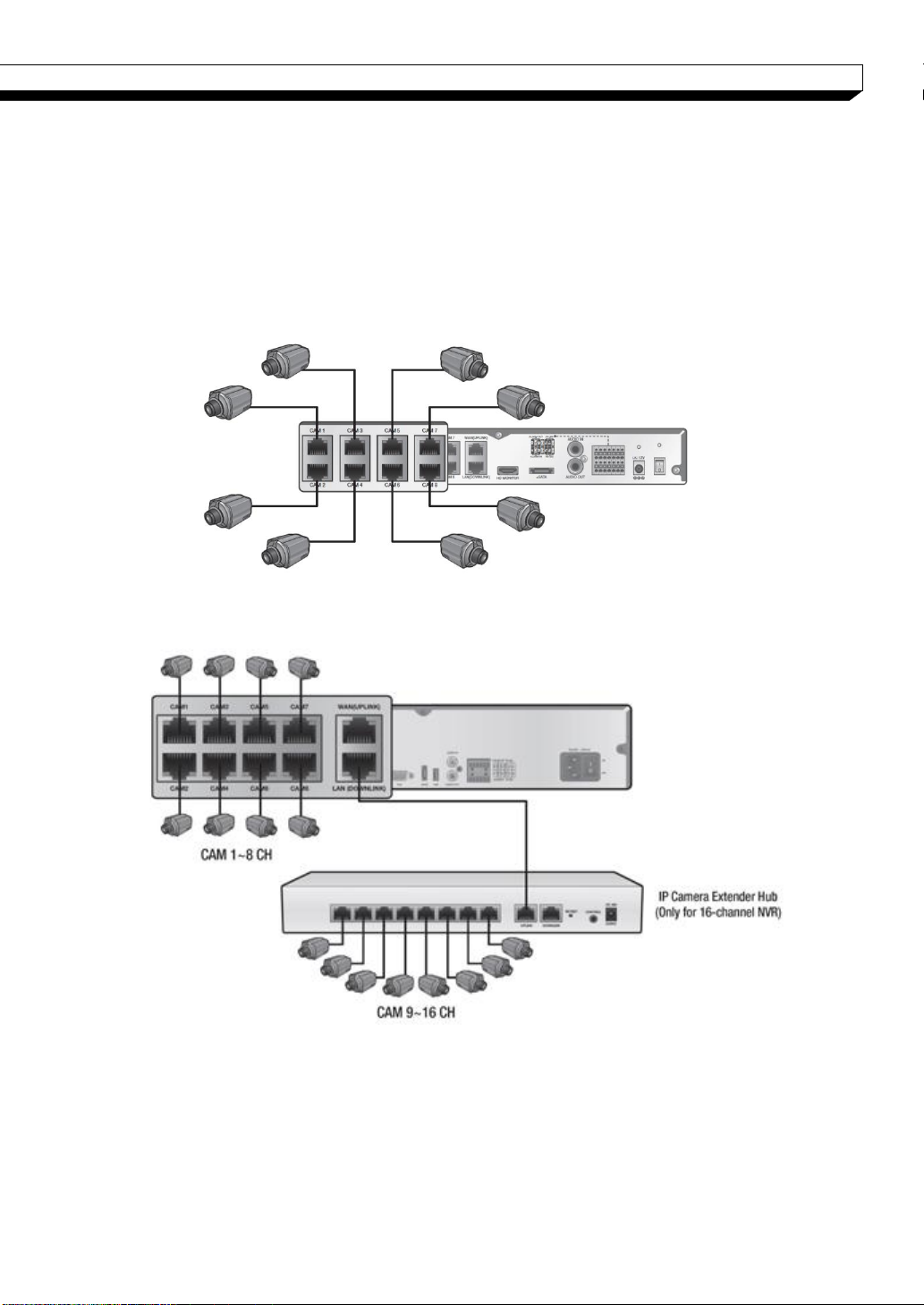
Connecting the camera
You can connect a PoE-featuring IP camera to the rear [CAM1]~[CAM8], RJ45 port using the
CAT5 10/100Mb Ethernet cable without a separate power source.
Connect IP cameras to the [CAM9] ~ [CAM16] ports of the hub, and connect
[LAN (DOWNLINK)] port and the hub’s [NVR] port with an Ethernet cable to establish
connections for channel 9~16 cameras (16ch only)
- NR4HL /NR8HL
- NR8H /NR16H
18
INSTALLATION
Camera
HUB or Router
NVR
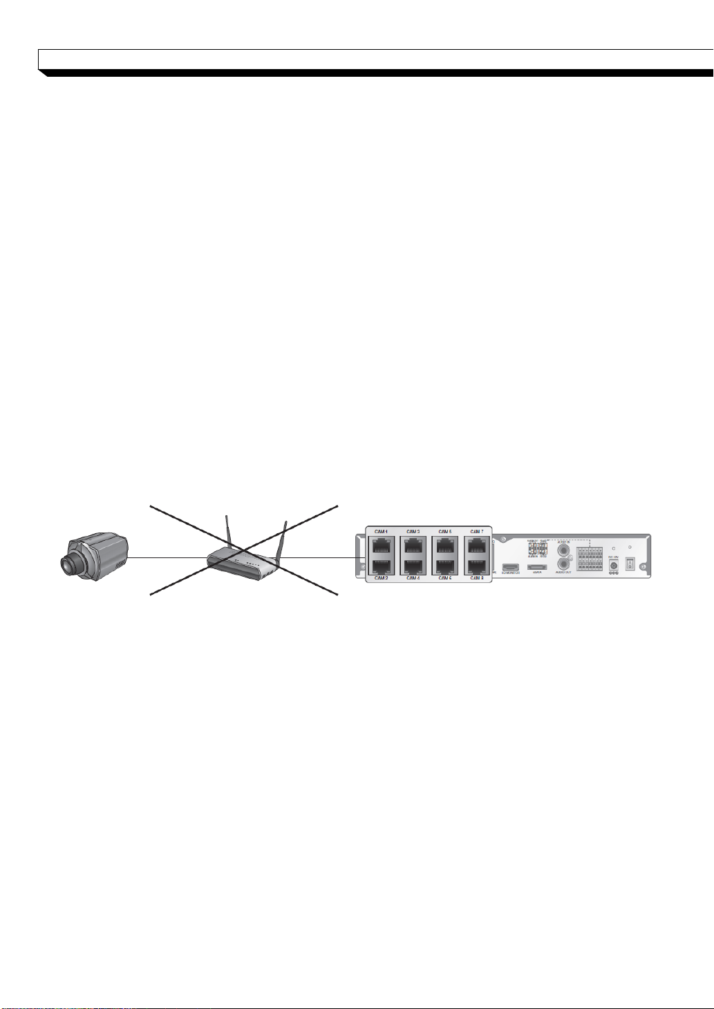
Precautions
To secure recording stability from an overloaded network traffic, hacking attempt or DoS
(Denial of Service) attack, only the direct cable connection between camera and NVR is
allowed.
If the IP camera provides the alarm I/O port or Audio I/O port, you can make
alarm or audio connection. For more details, refer to the user manual of the IP
camera.
The Ethernet connection is effective within 100 meter in distance. Beyond that, you
may encounter a data loss or failure to connect to the camera. If you need to make
cable connection of longer than 100 meters, use a separate PoE extender for cable
extension.
The total power consumption of the IP cameras should not exceed the rated power
capacity of the 48V PoE adaptor (Main unit; 95W external PoE hub: 72W for
NR8H/NR16H). Beyond that, the video may not be played properly or no video will be
displayed at all. If this is the case, use a separate (additional) power source for
supplying power to the cameras.
Even if total power requirement meets PoE device’s power capacity, a camera of more
than 15W power requirement per a port cannot be used.
Each camera’s power consumption can be checked on the network map screen, and
total power consumption should consider camera’s maximum possible consumption with
optional accessories (such as IR / heater device).
For stable operation, a dedicated communication line is established for IP cameras in
the same network. This is why network router or hub connection is not allowed.
19
INSTALLATION
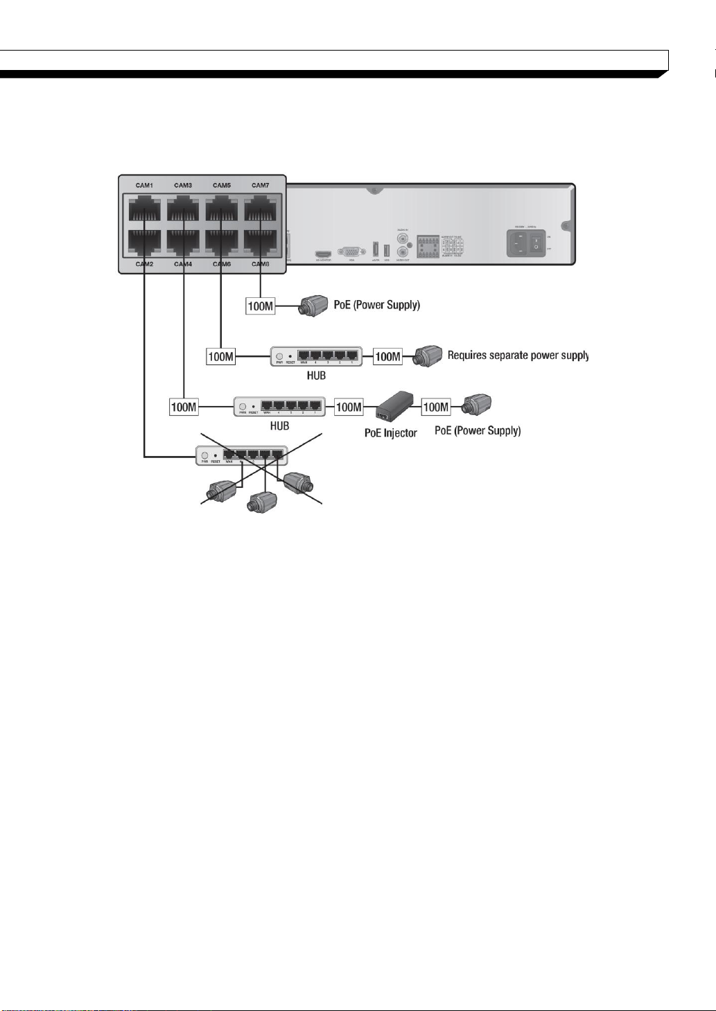
If the distance between the NVR and IP camera is more than 100m
You may extend the transfer range by connecting a switching hub or PoE device between
the Ethernet port and IP camera if desired distance is longer than 100m.
Connecting cameras directly to a general switching hub requires camera connected to a
separate power supply.
A switching hub connected for extending transfer range of a single channel should be
connected to one camera only.
20
INSTALLATION
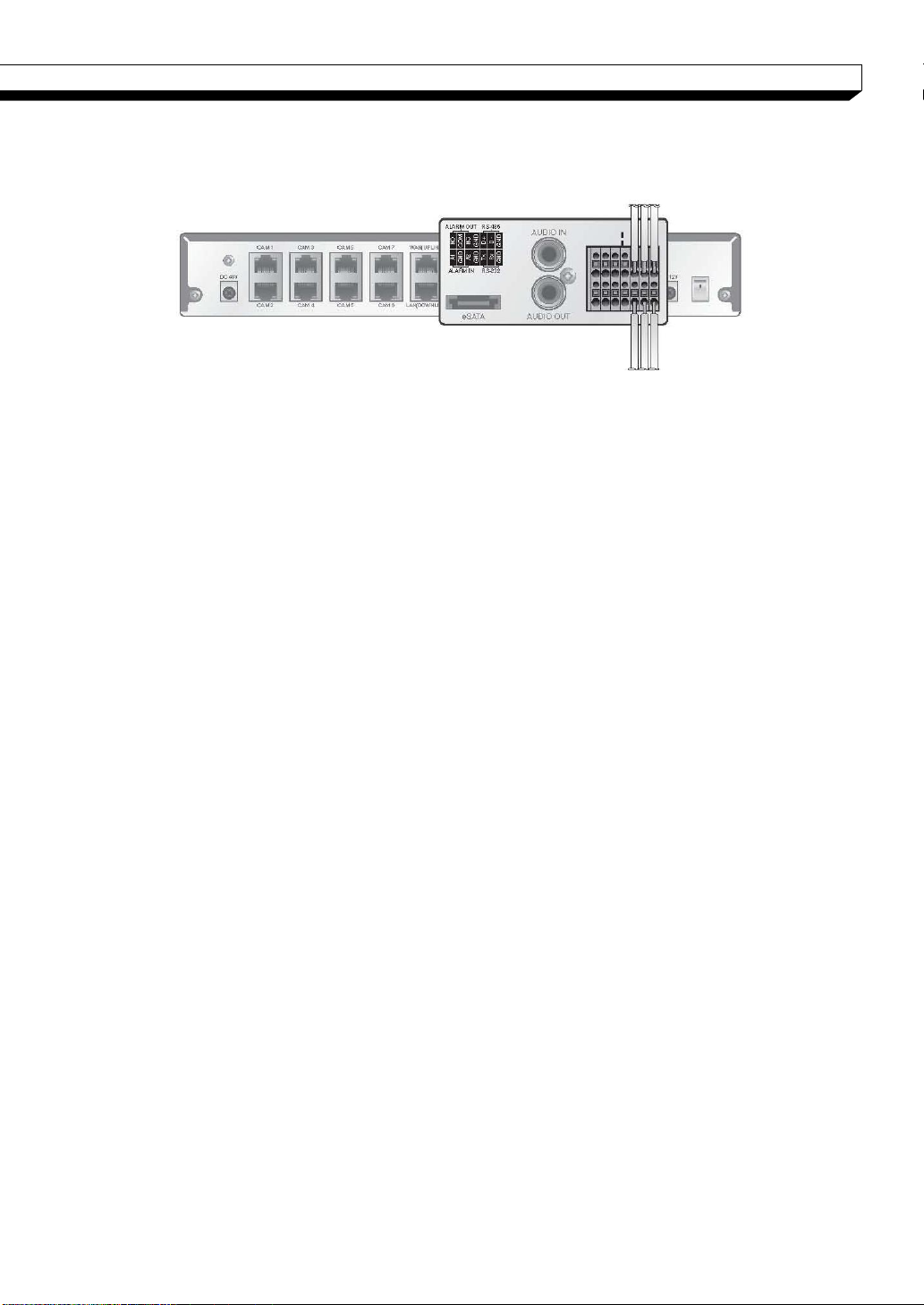
Alarm I/O Connection
To connect the alarm input signal
1. While pressing and holding the [A1] or [A2] port button in the rear bottom of the
NVR, insert the alarm signal cable in the hole under the button.
2. Insert the grounding wire in the [GND] port.
3. To ensure secure connection, release the button and pull out the wire to check if it's
not pulled out.
4. To remove the wire, pull it out while holding the upper button.
To connect the alarm output signal
Connect the signal line of an alarm output device to the rear [ALARM OUT] port.
1. Check the relay output type of Normal Open or Normal Close before selecting a
proper type (N/O or N/C). While holding the [N/O] or [N/C] button, arrange the
alarm signal cable through the hole under the button.
N/O(Normal Open) : normally Open but switching to Close if an alarm out occurs.
GND : Insert the grounding wire.
N/C(Normal Close) : normally Close but switching to Open if an alarm out occurs.
2. Insert the grounding wire in the [GND] port.
3. To ensure secure connection, release the button and pull out the wire to check if it's
not pulled out.
4. To remove the wire, pull it out while holding the upper button.
21
INSTALLATION
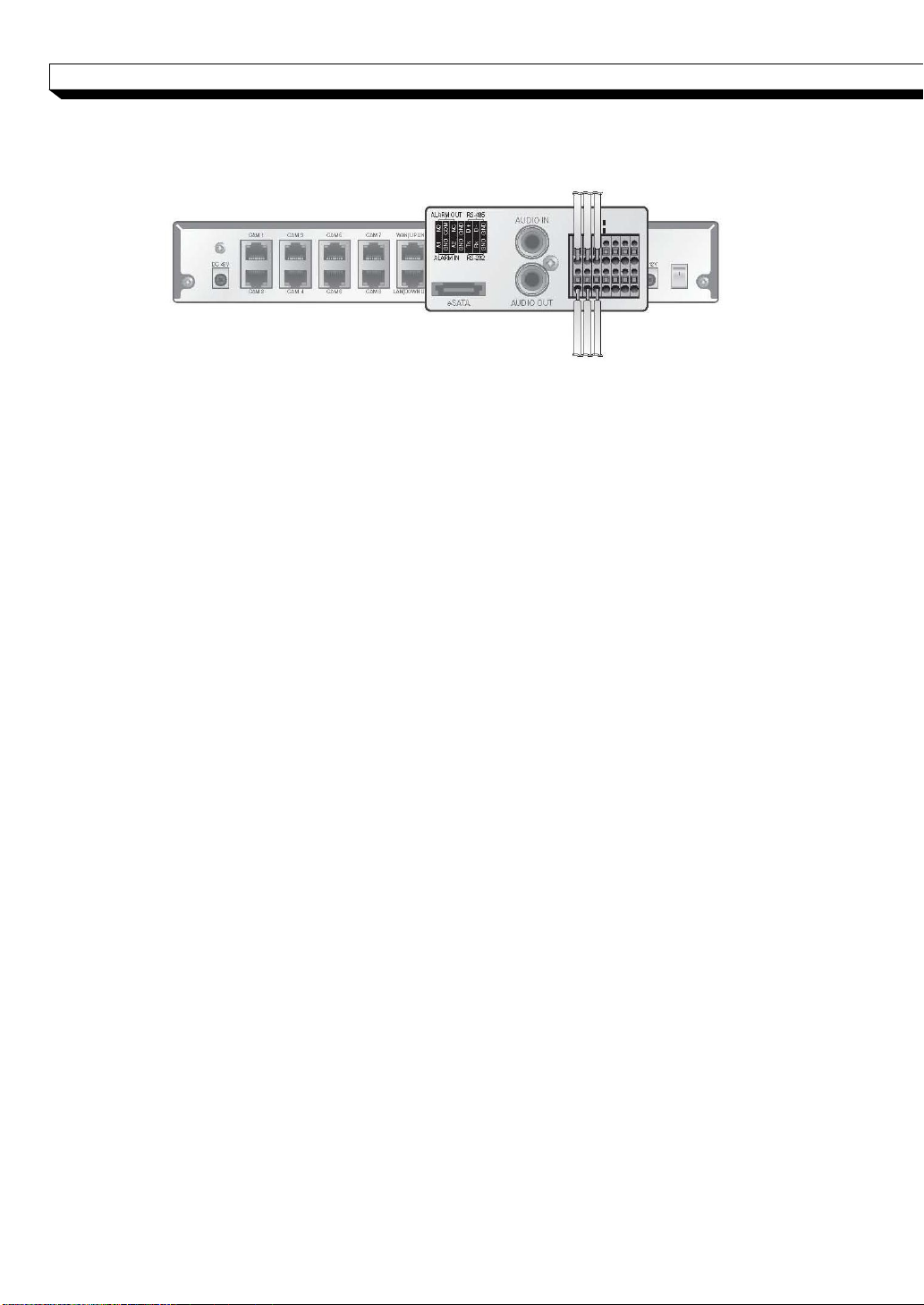
Communication Port
RS-485 Connection
Connect the keyboard controller.
You can connect a text-in device such as POS or ATM. After connecting the control device,
be sure to match the connection settings between NVR and device. Make communication
settings in <Control Device>. (page 55)
1. Use the signal line to make connection between [D+] of the rear NVR and [D+] of
the keyboard controller.
2. Make connection between [D-] of the rear NVR and [D-] of the keyboard controller.
3. Make connection between [GND] of the terminal block plug and [GND] of the
keyboard controller.
4. Install the wire-connected terminal block in the rear part.
For RS-485 connection, refer to the user manual of the keyboard controller.
Signal connection for POS and ATM is scheduled to be upgraded later.
RS-232 Connection
You can connect a text-in device such as POS or ATM.
For connection of the text-in device, refer to the user manual of the text-in device.
Signal connection for POS and ATM is scheduled to be upgraded later.
Audio Device Connection
You can connect an audio output device such as speaker amplifier.
Connect the audio input device such as microphone to the rear Audio In port, connect the
audio output device such as speaker amplifier to the Audio Out port.
22
INSTALLATION
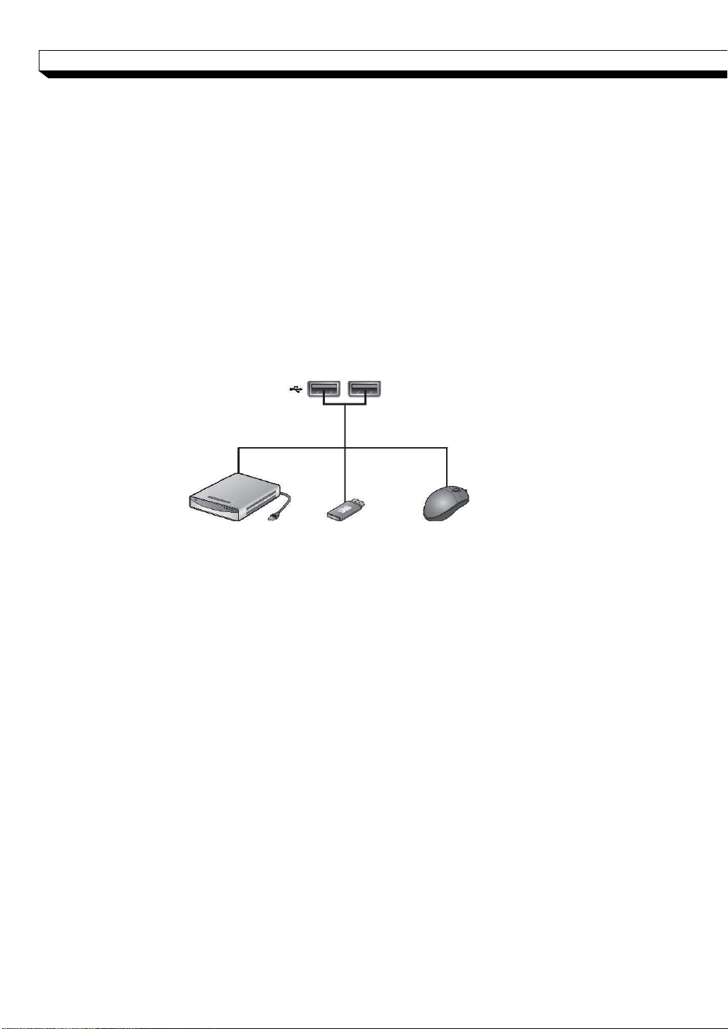
External HDD
(For backup only)
USB Storage
Mouse
eSATA Storage
If the internal storage space is insufficient, you can extend your storage capacity by adding
an eSATA storage device to the rear eSATA port.
Recommended eSATA device
-Manufacturer : Sarotech
-Model : C5-US3-N
Using devices other than recommended eSATA products may cause serious problem.
USB Device
You can connect a USB storage device for backup of recorded video, saving snapshot, updating the
firmware, importing/exporting user data or settings. You can also connect the USB mouse to control
all operations of the NVR.
If you need to connect a USB HDD with a high power consumption, it is
recommended to use a separate power source for that HDD.
23
INSTALLATION
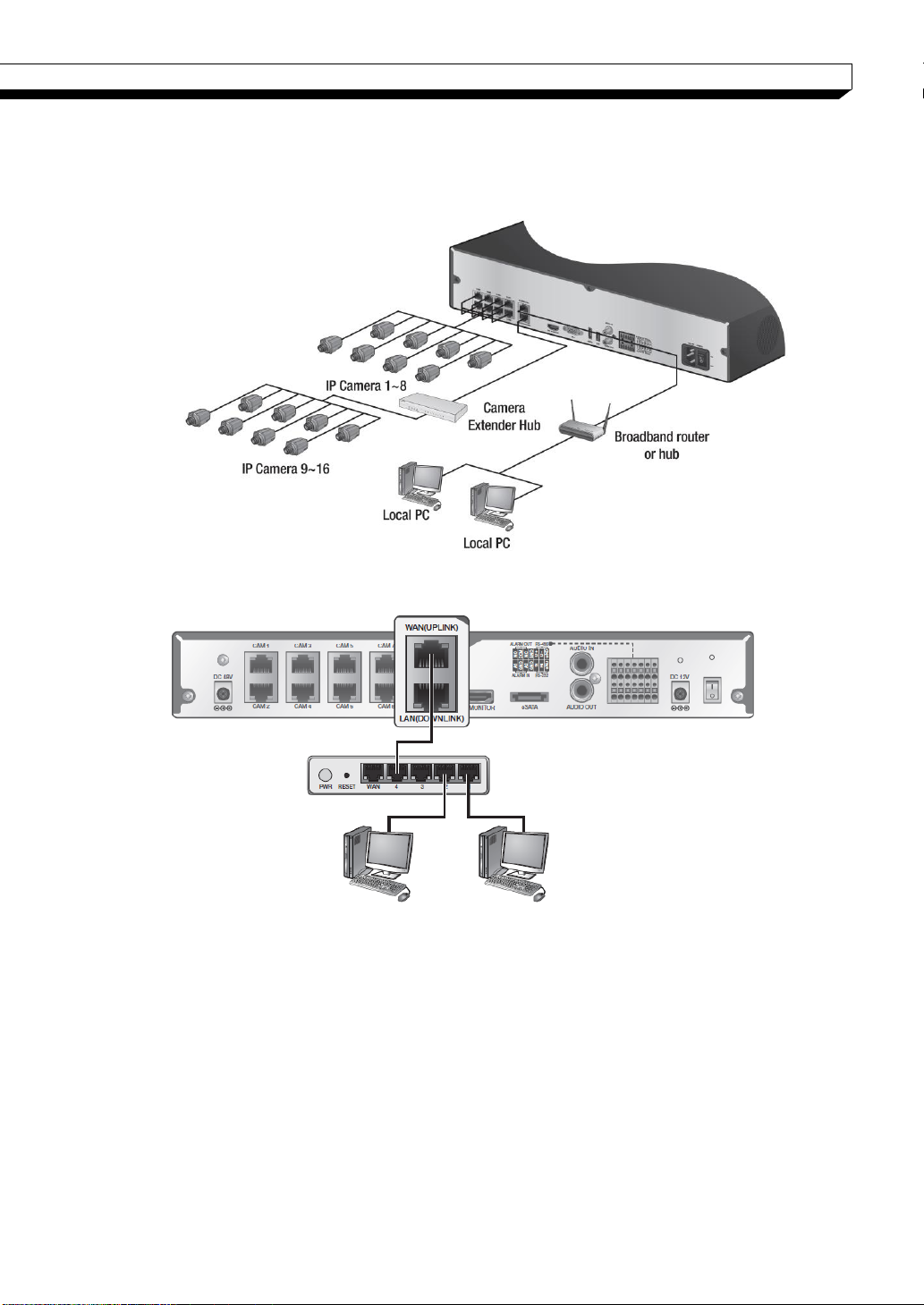
Broadband Router or Hub
Local PC
Local PC
Network Connection
PC connection in the local network
You can connect NVR to a PC in the same network and control or manipulate it on the PC
monitor.
1. Connect the [WAN(UPLINK)] port in the rear panel to the router or hub.
2. Connect the local PC to the router or hub.
3. Enter the address in the address bar (web browser) of the local PC or of the dedica
ted software program in the format of “http://IP address:web service port ”.
(Ex : http://192.168. 1.23:8080) The web service port is set to 8080 by default. From
the Network Setup screen, you can change the port number.
4. Provide the ID and password before logging in. Then, you can view the monitoring s
creen. Access ID (factory default) : ADMIN, P/W : 1234.
For the security purpose, change the password right after you purchased the pro
duct.
24
INSTALLATION
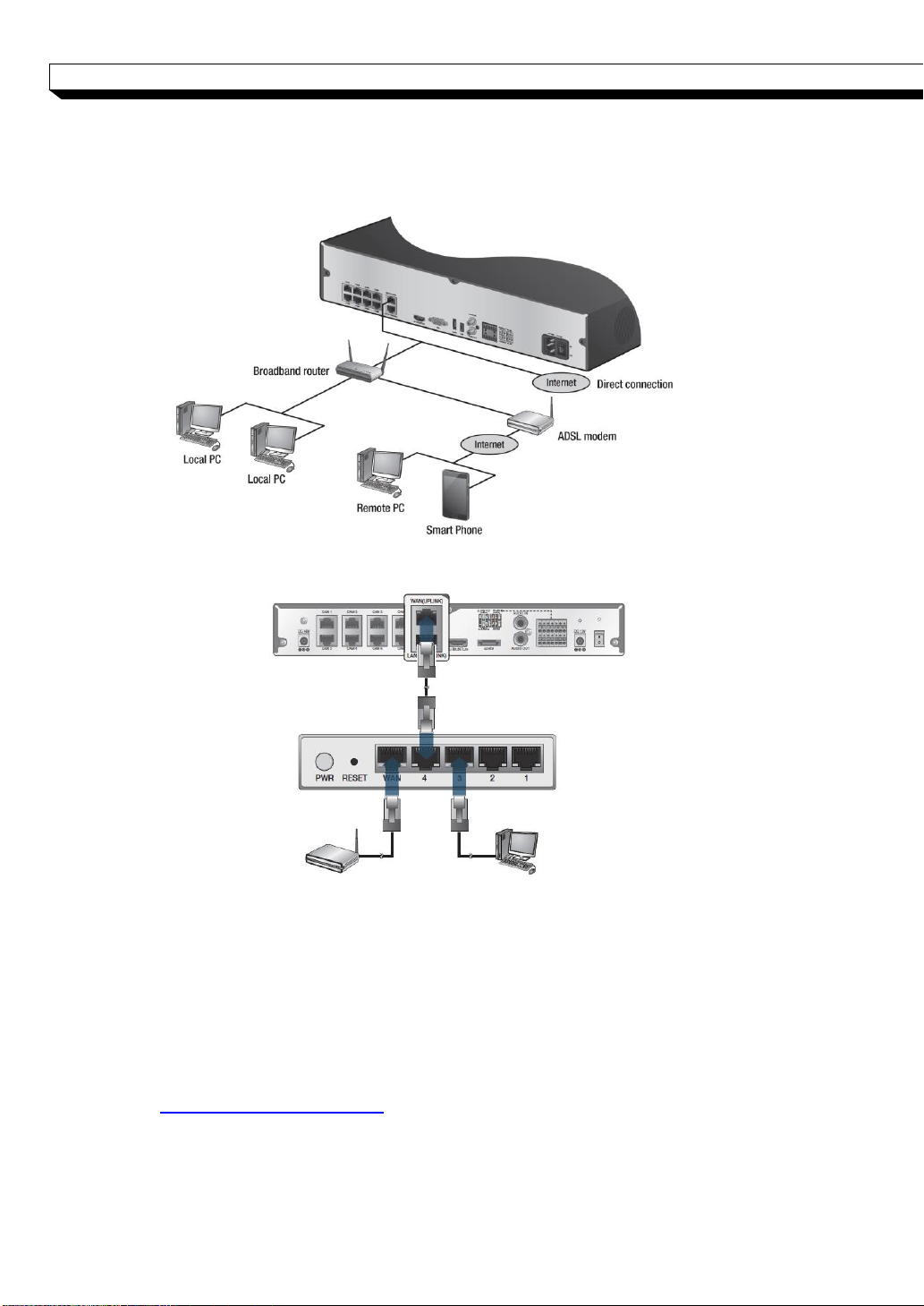
Broadband Router
Local PC
ADSL Modem
PC connection from a remote network
You can connect NVR to a PC or mobile device in the same remote network and control or
manipulate it on the monitor of the PC or mobile device
1. Connect the [WAN(UPLINK)] port in the rear panel to the router.
2. Connect the [WAN(UPLINK)] port of the router directly to the fixed IP LAN cable,
or connect it to the ADSL modem.
3. If using the router, set the port forwarding and enter the DDNS address in the
address bar (web browser) of the remote PC, or of the dedicated software program
or mobile phone.
For the IP and DDNS address settings, refer to “Network Setup”. (page 47)
4. If the MAC address of the NVR is 00-1C-B8-12-34-56 and the web port number is
8080, enter "http://001CB8123456.dvrlink.net:8080" in the address bar of the web
browser.If you have renamed DDNS as “mydvr”, you can make network connection
at http://mydvr.dvrlink.net:8080
25
INSTALLATION
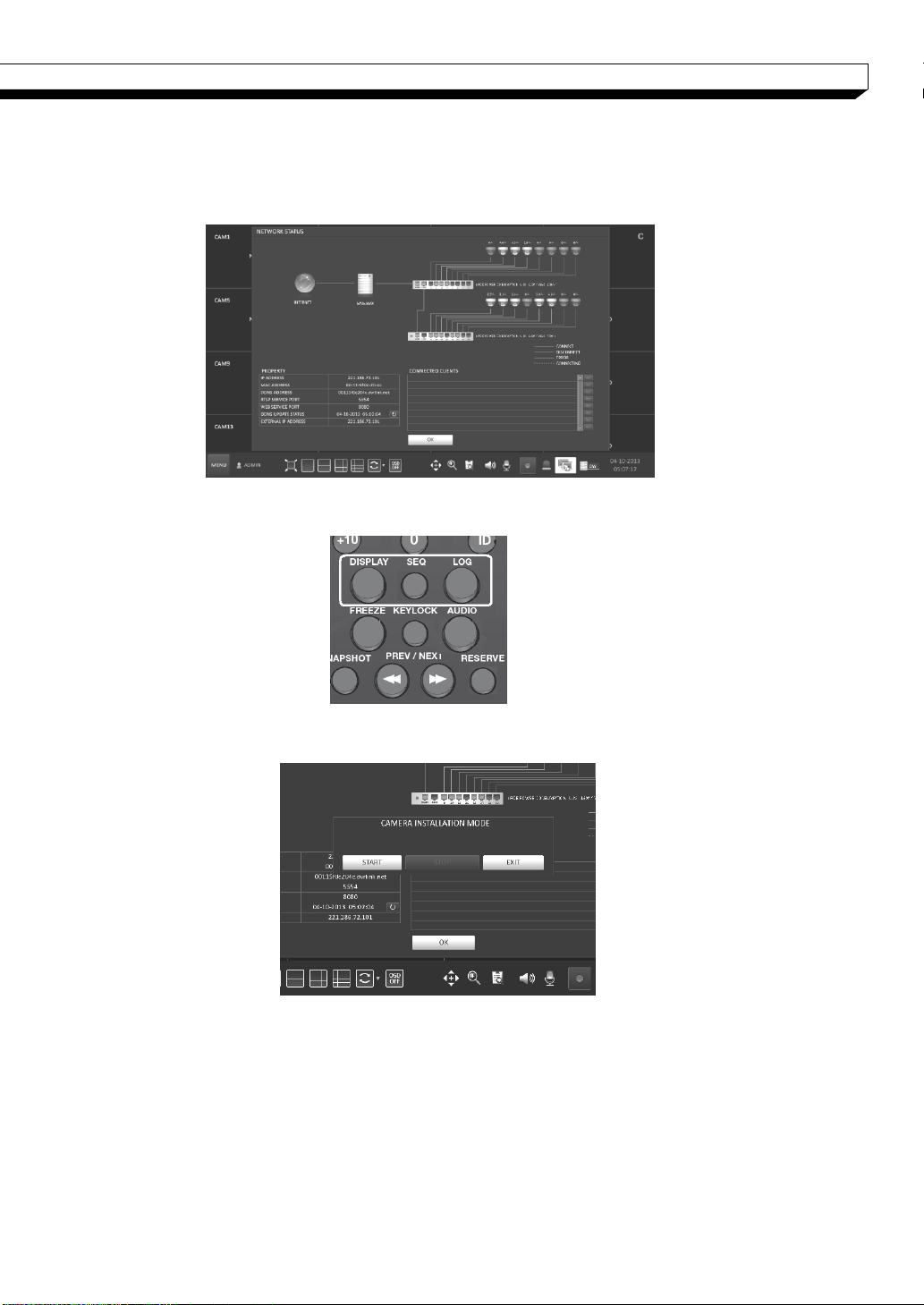
Camera installation mode
You can set all connected cameras into installation mode for analog video output monitoring.
Click network status icon on the live view screen to open network status window.
Press <DISPLAY>, <SEQ>, and <LOG> in order by remote control to open “CAMERA
INSTALLATION MODE” Menu
Click <START> to change cameras to installation mode.
When done, click <STOP> and click <Exit> to back to normal mode.
26
Monitoring
Start Up/ Shutdown
START
You can connect NVR to a PC in the same network and control or manipulate it on the PC
monitor.
1. Connect the adaptor to the 48V PoE power input
Make connection when the power is not applied yet.
2. Connect the adaptor to the 12V power input port in
3. Turn on the power switch in the rear panel of NVR.
4. When the booting process is completed, the live
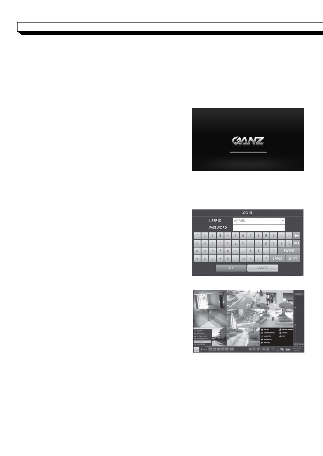
Log In
To manipulate or access the menus of NVR, you should have logged in.
1. When the system starts, the login screen appears.
2. Select a user and provide the password.
3. Click <OK>.
For the security purpose, change the password right
Log Out
To prevent unauthorized access, it is recommended to
log out when you leave the screen.
Hover the cursor near the bottom of the screen to
1. In the monitoring screen, click <MENU> in the
2. Access to Search / Backup / System Setup / Record Setup / System Shutdown will be
port in the rear panel of NVR.(NR4HL/8HL)
Or connect to external Hub(NR16H)
the rear panel of NVR.(NR4HL/8HL)
Connect AC cord to rear panel.(NR8H/16H)
With a beep, the logo screen appears several
seconds after the front LED turns on.
screen then the login screen appears.
The default password of the "ADMIN" account is
"1234".
If the login information is correct and valid, you will
see the live screen.
after you purchased the product.
.
display the menu.
bottom left corner of the screen to <LOG OUT>, or
press the [LOGOUT] button on the remote control.
restricted.
27
Monitoring
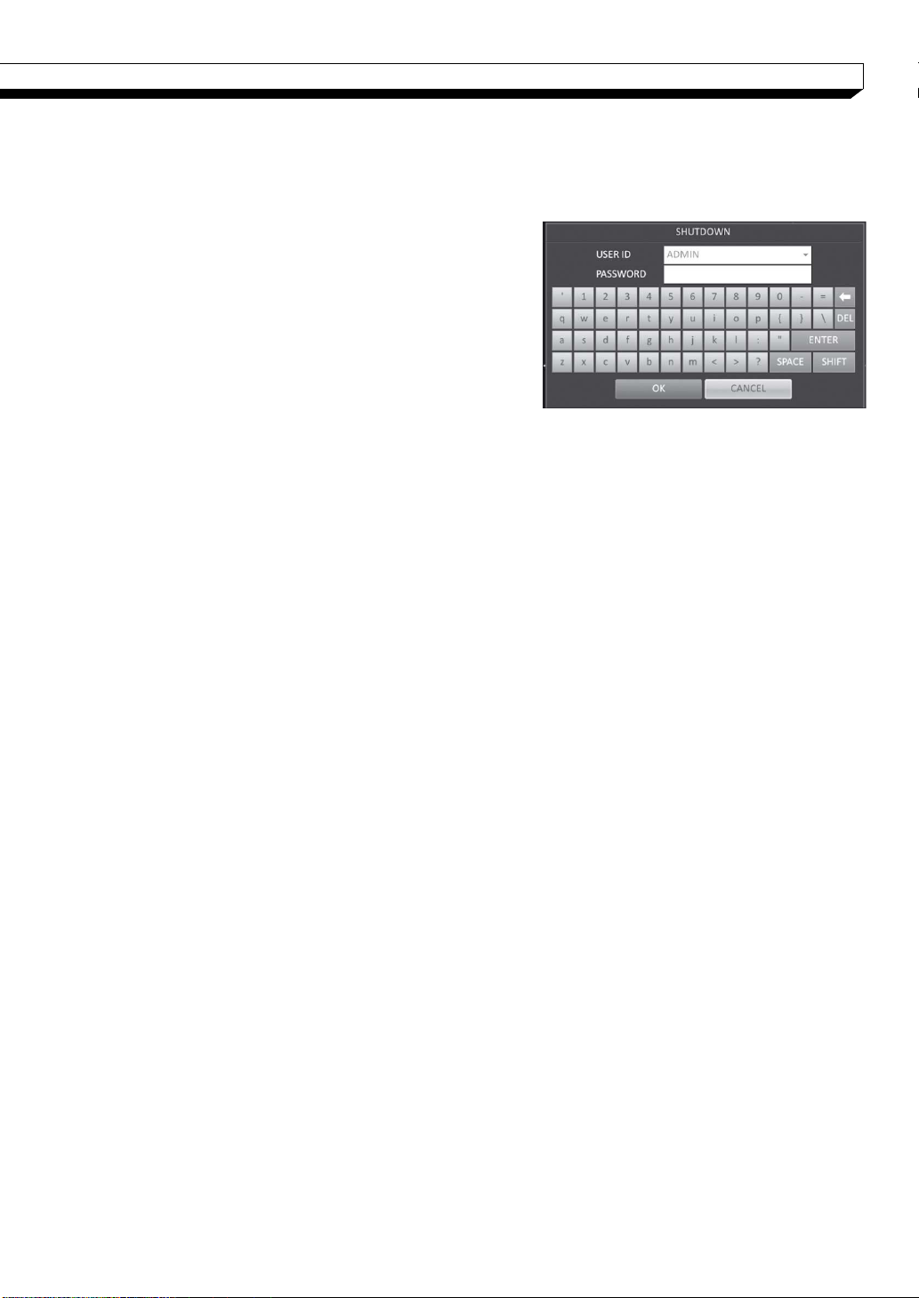
System Shutdown
You can connect NVR to a PC or mobile device in the same remote network and control or
manipulate it on the monitor of the PC or mobile device
1. In the monitoring screen, click <Menu> in the
bottom left corner of the screen to <SHUTDOWN>
the system, or press the [POWER] button on the
remote control.
2. Use the virtual keyboard to enter the password.
3. Be sure to turn off the power switch in the rear
panel.
If you turn off the system in an abnormal manner
such as removing the power cord while the system
is in operation, the disk will have or increase the
bad sectors, causing data loss and shortened life cycle of the disk.
28
Monitoring
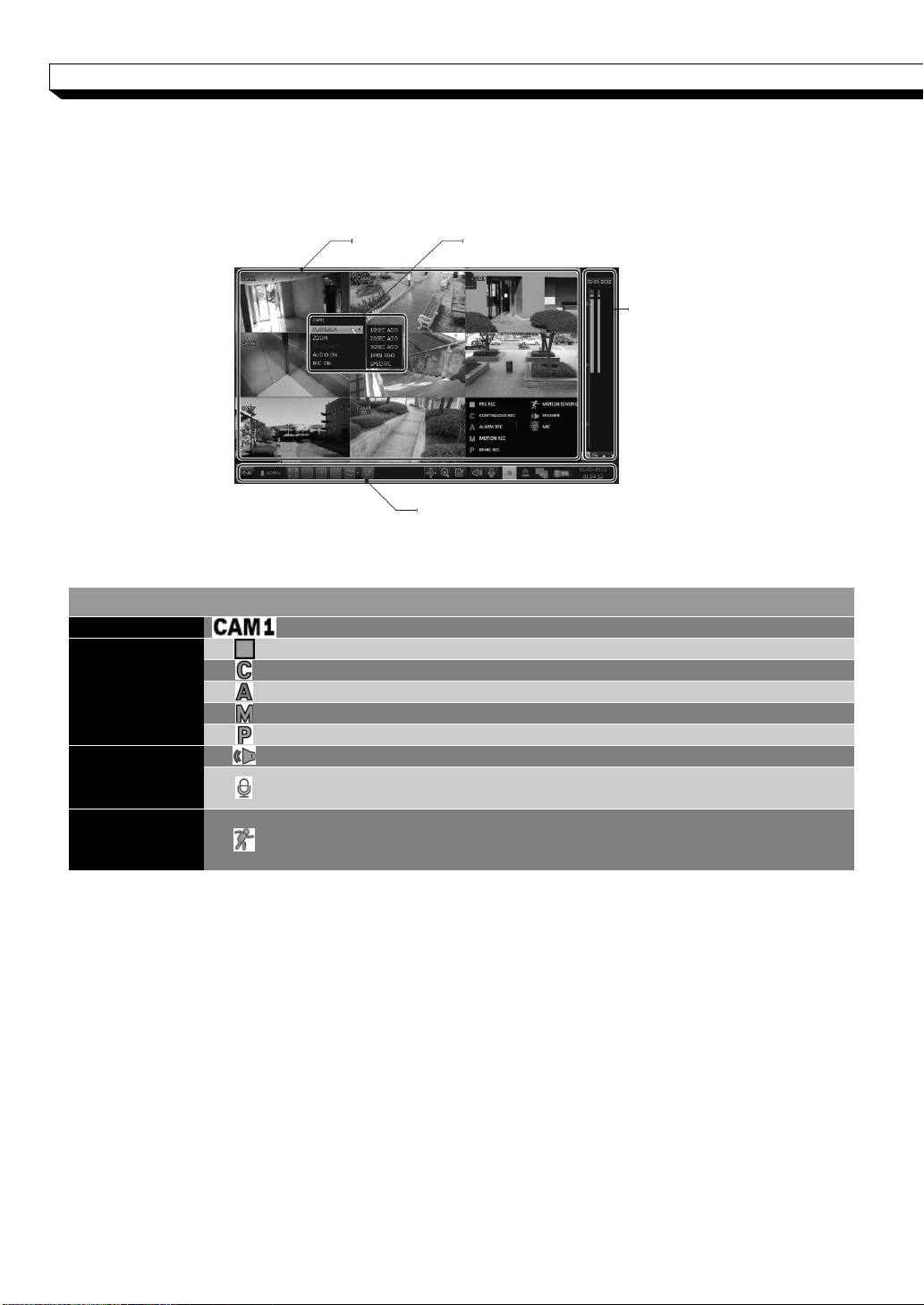
ITEM
Description
Camera ID
Show the camera ID
Record Mode
Icons
Displayed if an event recording is reserved.
Display the status of the continuous recording.
Display the recording status when an alarm occurs.
Display the recording status when a motion event occurs..
Display the status of the emergency recording..
Audio
I/O Icons
The audio signal of the connected camera is outputting.
The audio signal is transferring to the connected camera via the
microphone.
Motion Detect
ion
Icon
A motion is detected by the connected camera.
Status Bar
Timeline
Quick Menu
Video Window
Live Screen At a Glance
The live screen largely consists of three components: video window, status bar and timeline z
one.
Video Window
Icons used in the video window.
29
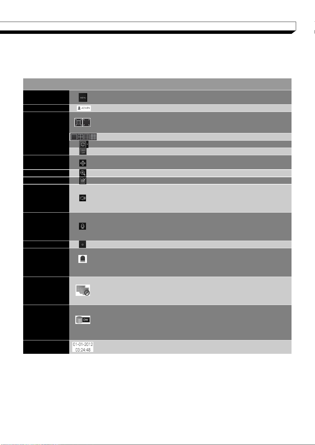
Monitoring
ITEM
Description
Menu Button
Select one of the system setup, search and backup menu it
ems before accessing it.
User ID
Show the ID of the user who has currently logged in.
Screen Contr
ol
Buttons
Edit the screen layout to show the status bar and timeline at
all times or only when the mouse cursor hovers on the stat
us bar/timeline
Select a split mode.
Select Auto Sequence or Special Split Mode.
Display or hide the OSD menu on the screen.
PTZ
Move to the PTZ screen. You can control the PTZ operation
s of a PTZ-compliant camera on the PTZ screen.
Zoom
Move to the Digital Zoom.
Quick Log
Display the log list of the recent recording events.
Audio Chann
el
Selection Butt
on
You can use the camera supporting the audio input to listen
to the audio.
Microphone
Channel Sele
ction
Button
Select a camera to which the audio signal will be transferred
from the connected microphone.
Panic Record
Start the panic recording.
Alarm Indicator
Turns on if an event occurs. It does not turn on if no reacti
on to the event is yet defined.
Click this to check the information of the event that occurre
d.
Network
Connection S
tatus
Check if network connection is made via an external PC or
mobile device. Click this to view the details of the concurrent
users and to check the network connection status. For mor
e information, refer to "Network Setup". (page 47)
Disk Space
Show the disk space information. If you have set the disk o
verwrite mode, it will be displayed "OW" (Over Write) from th
e start point of the overwriting. Click this to view the details
of the disk status. For more
information, refer to "Record Setup".(page 66)
Date & Time
Display the current time and date.
Status Bar
Press the ▼ button on the remote control, or place the mouse in the lower area of the
screen to display the status bar.
30
 Loading...