

Page 1
License Plate
090121-1
Capture Camera
INSTRUCTION MANUAL
Version Date: 11/9/11
Please read this manual carefully before installation and operation of the product.
Page 2
Dear Customers!
By selecting this product, you have decided to use a professional device that
guarantees highest quality and reliability. We would like to thank you very much for your
confidence and kindly ask you to read the following instructions carefully before
Installation and operation in order to take full advantage of all quality features regarding
this product.
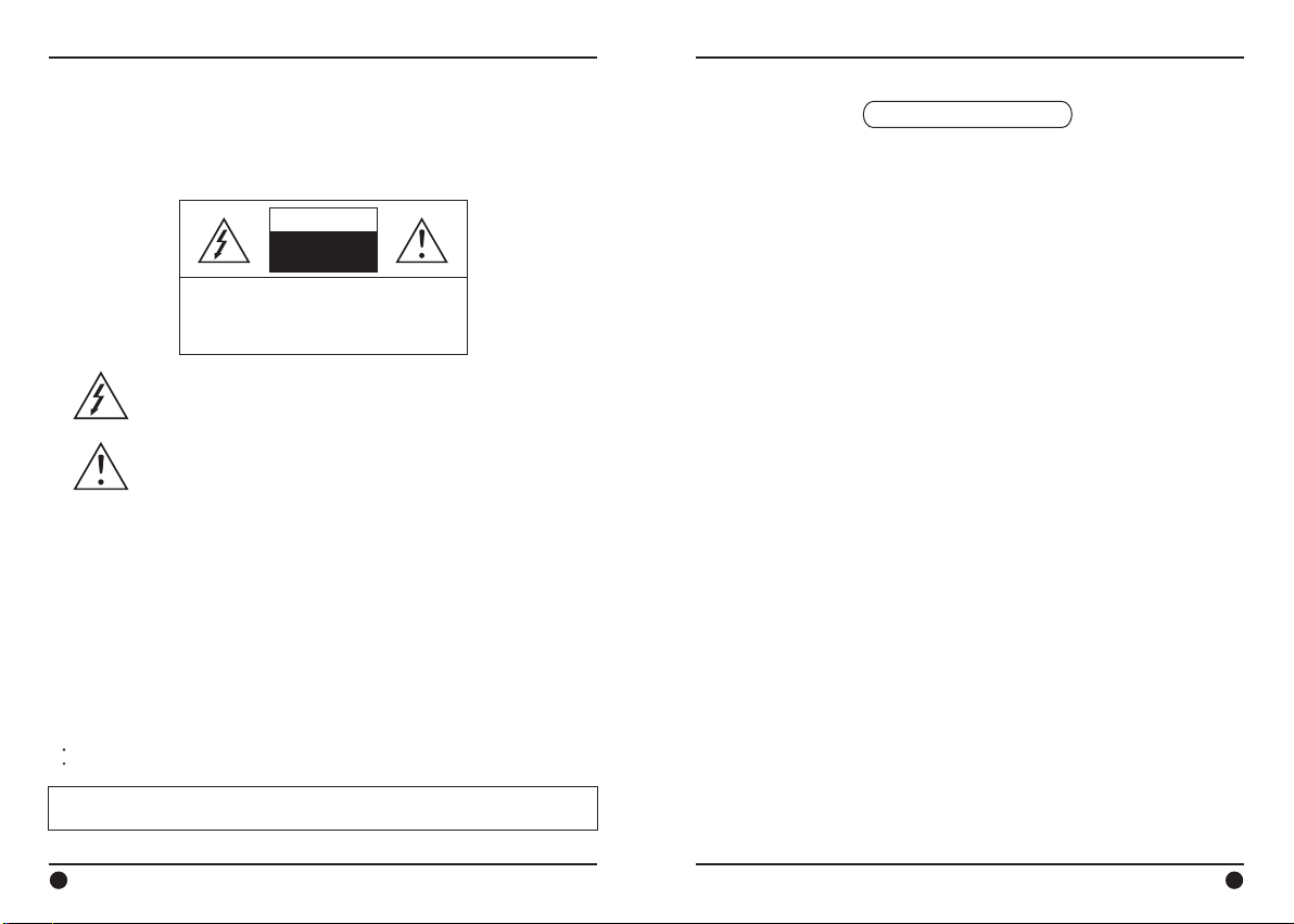
CAUTION
RISK OF ELECTRIC
SHOCK
DO NOT OPEN
TO REDUCE THE RISK OF ELECTRIC SHOCK,
DO NOT REMOVE THE COVER (OR BACK).
REFER SERVICING TO QUALIFIED PERSONNEL.
The lighting flash with an arrowhead symbol, within an equilateral
triangle is intended to alert the user to the presence of uninsulated
dangerous voltage within the product’s enclosure that may be of
sufficient magnitude to constitute a risk of electric shock to persons.
The exclamation point within an equilateral triangle is intended to alert
the user to the presence of important operating and maintenance
(servicing) instructions in the literature accompanying the appliance.
INFORMATION
This equipment has been tested and found to comply with limits for a Class A digital
device, pursuant to part 15 of the FCC Rules. These limits are designed to provide
reasonable protection against harmful interference when the equipment is operated in a
commercial environment. This equipment generates, uses, and can radiate radio
frequency energy and, if not installed and used in accordance with the instruction
manual, may cause harmful interference to radio communications. Operation of this
equipment in a residential area is likely to cause harmful interference in which case the
user will be required to correct the interference at his own expense.
CAUTION
NO USER SERVICEABLE PARTS INSIDE.
WARNING
Changes or modifications not expressly approved by the manufacturer could void the
user’s authority to operate the equipment.
CAUTION – To prevent electric shock and risk of the fire hazards
Do NOT use power source other than that specified.
Do NOT expose this appliance to rain or moisture.
This installation should be made by a qualified service person and should conform to
all local codes.
Table of contents
1. Precautions ---------------------------------- 4
2. Limitation of liability ---------------------------- 5
3. Disclaimer of warranty -------------------------- 5
4. Package ------------------------------------- 6
5. Installation --------------------------------- 7-9
5-1. How to mount to Celling
5-2. How to install to Wall
5-3. 3-Axis adjustment
5-4. Rear Hole Plugs
6. Overview ------------------------------------ 10
7. Main Features ----------------------------- 10~11
8. Troubleshooting ------------------------------ 12
9. Specifications -------------------------------- 13
10. Dimension ---------------------------------- 13
2 3
Page 3

1. Precautions 2. Limitation of liability
· Please read the manual carefully before the installation in order to make use the
camera to be set up correctly and to have the best picture quality.
·
Please keep the manual in good condition for your future reference and service
application.
·
Installation and services should only be carried out by an authorized personnel
according to local safety regulations.
·
If any liquid or solid matter gets into the housing, immediately disconnect the camera
from power supply and have it checked by your authorized dealer before reusing.
·
Avoid installing the camera at extremely hot or cold places.
·
If you are not a certified person, never try to dismantle the camera. To avoid electric
shock, never remove the screws or covers. There are no parts inside that need
maintenance by the user. All maintenance should be carried out by qualified
personnel.
·
Avoid installing the camera at a place of high humidity.
·
Avoid installing the camera at the place exposed to gas or oil.
·
Keep the top glass of the lens always clean in order to obtain the best picture quality
all the time. Be careful not to be stained by fingerprint.
·
Don't face the camera directly toward sunlight or sunlight reflecting area.
CCD may go defective at this condition.
·
Please give a special attention to keep the unit from dangerous drop or external shock
during the process of transportation or handling.
·
Never try to touch the camera in wet hand. It may cause an electric shock.
·
Do not expose the camera to radioactivity. It causes a serious damage on the CCD.
· Install away from electric or magnetic fields.
This publication is provided “AS IS” without warranty of any kind, either express or
implied, including but not limited to, the implied warranties of merchantability, fitness
for any particular purpose, or noninfringement of the third party's right. This publication
could include technical inaccuracies or typographical errors. Changes are added to the
information herein, at any time, for the improvements of this publication and/or the
corresponding product(s).
3. Disclaimer of warranty
In no event shall seller be liable to any party or any person, except for replacement or
reasonable maintenance of the product, for the cases, including but not limited to
below :
(1) Any damage and loss, including without limitation, direct or indirect, special,
consequential or exemplary, arising out of or relating to the product;
(2) Personal injury or any damage caused by inappropriate use or negligent operation
of the user;
(3) unauthorized disassemble, repair or modification of the product by the user;
(4) Inconvenience or any loss arising when images are not displayed, due to any reason
or cause including any failure or problem of the product;
(5) Any problem, consequential inconvenience, or loss or damage, arising out of the
system combined by the devices of third party.
(6) Any claim or action for damages, brought by any person or organization being
photogenic subject, due to violation of privacy with the result of that surveillance camera's picture, including saved data, for some reason, becomes public or is used
for the purpose other than surveillance.
4 5
Page 4

4. Package 5. Installation
Power + V ideo Cable
1E A
5-1. How to mount to Celling
License Plate
Capture Camera
INSTRUCTION MANUAL
License Plate
Capture Camera 1EA
Mounting screws
3EA
Please read this manual carefully before installation and operation of the product.
Instruction manual
1EA
Plastic anchor
3EA
Power + Video Cable
1EA
Plastic anchor
(B)
Mounting Screw
(Ø4x30L_3EA)
(A)
① Drill three screw holes on the ceiling plate to fix three plastic anchors (supplied) in
the holes.
② Fix the plastic anchors in the holes.
③ Position the mounting bracket on the screw points.
④ Fix the mounting bracket by tightening the screws.
⑤ Slightly loosen knob (A) then adjust tilt(180˚) and rotation(360˚) of the camera and
tighten the knob firmly.
⑥ Slightly loosen knob (B) then adjust pan(360˚) of the camera and tighten the knob
firmly.
6
7
Page 5

5. Installation 5. Installation
5-2. How to install to W al l
(A)
Plastic anchor
Mounting Screw
(Ø4x30L_3EA)
(B)
① Drill three screw holes on the wall plate to fix three plastic anchors (supplied) in the
holes.
② Fix the plastic anchors in the holes.
③ Position the mounting bracket on the screw points.
④ Fix the mounting bracket by tightening the screws.
⑤ Slightly loosen knob (A) then adjust tilt(180˚) and rotation(360˚) of the camera and
tighten the knob firmly.
⑥ Slightly loosen knob (B) then adjust pan(360˚) of the camera and tighten the knob
firmly.
Power cable
Video output cable
(Red)
(Black)
5-3. 3-Axis adjustment
Pan knob
Tilt knob
ROTATE(360˚)
TILT(180˚)
① Pan 360˚
Slightly loosen Pan knob then adjust pan of the camera and tighten the knob firmly .
② Tilt 180˚
Slightly loosen Tilt knob then adjust tilt of the camera and tighten the knob firmly.
③ Rotation 360˚
Slightly loosen Tilt knob then adjust rotation of the camera and tighten the knob firmly.
5-4. Rear Hole Plugs
A
Hole Plug
① NOTE: No User Zoom/Focus controls exist on this camera!
The LP camera uses parts common to another camera. Although the rear plate is
labeled with “Zoom” & “Focus” controls, none exist with this fixed lens camera.
These are merely hole plugs.
N O
W T
O
C
Hole Plug
B
Hole Plug
8
9
Page 6

6. Overview
This unit is one of the most advanced license plate cameras available. Installed in
parking lots, gated access or toll roads, this specialized camera combines several
key technologies to allow positive numeric ID from vehicles day or night.
The use of IR illumination and special optical filters eliminate headlight glare,
allowing License Plate numbers to reflect IR light for optimum recognition. The
high shutter speed, high sensitivity CCD minimizes motion blur, providing positive
numeric ID from vehicles moving up to 31mph.
7. Main Features
A. License Plate Capture
Note: This LP camera is highly optimized for license plate recognition under the
most adverse conditions. As such, it has some idiosyncrasies you might not
expect. To minimize headlight glare at night, it has an optical filter designed to
suppress visible light, but pass IR illumination. It also has a fixed high shutter
speed of 1/1000 second. By combining these technologies with IR LED’s, it will
effectively suppress objects lit by visible light, and mostly resolve reflective
license plates illuminated by the IR LED’s. As a consequence of this optimization, you will get a low-contrast view of the vehicle, day or night. However, you
will get a clear image of any reflective license plate, even while the vehicle is
moving.
7. Main Features
0 LUX
24VA C
Ip67 H arsh
24
VDC
Weat herpr oof
1/3”
SONY B/W
Ex-view CCD
· 1/3” SONY B/W Ex-View CCD
·
High resolution of 600TVL
·
16mm or 35mm fixed omni-focus lens with multi-focusing technology
·
Capture plates from vehicles moving up to 31mph (50km/hour)
·
Intelligent IR Protection Technology extends the usable lifetime of IR LEDs
·
IR LED brightness adjustable, up to 33’ (10m) distance w/ 16mm lens (60’ w/ 35mm lens)
·
DC24V or AC24V Non-polarity power input
·
3-Axis camera bracket conceals cabling for clean and simple installation
·
IP67 Weatherproof
Resol ution
600T VL
High
IR
10M
at “0 ” Lux
10
Conventional
B. Adjustment of IR LED brightness
screw cap
LP Camera
Remove the screw cap from the
bottom of the camera. Adjust the IR
LED brightness by the potentiometer
mounted to the PCB.
potentiometer
1 1
Page 7

8. Troubleshooting 9. Specifications
Effective Pixels
Digital Slow Shutter
Operating current
H.Resolution
Scanning system
Before sending the camera out for repair, check the items below. If the problem persists after
checking these items, contact your service center.
Problems Trouble shooting
Nothing appears on the
screen.
The video image is not
clear.
The screen is dark.
The camer a ’ s surface is too
hot and black strip e s
appear on the screen.
The screen is flickering.
IR beam is weak
Please check the power connection.
Please check the video signal line connection .
Pl ease chec k if the lens or the outer glass is clean.
- Dirt or f ingerprints on the lens can affect the image
blooming or reflection. Gently wipe any dirt or
fingerprints off the lens or the glass with a soft cloth.
Please check and adjust contrast feature o f the monitor
Please check if the camera is exposed directly toward a
bright light, sunlight, or sun light
Please move the camera ’ s position in this case.
This is normal, because of the optical filter that rejects visible
light and the high-shutter speed. Mainly highly reflective
objects within 31’ range of the IR LED’s will be visible. For
most applications, this would be the license plate from most
modern vehicles. See Notes in Overview section on page
10.
Please check if the power supply is regul a ted and is
within the standard requirem ent of the product.
Please check if the camera is facing directly toward
sunlight or fluorescent light .
Adjust the potentiometer to increase IR LED brightness. See
page 11. Verify cable conductor gauge is adequate for the
cable run. Using too thin gauge of Power wire can cause
serious voltage drop, especially over long distance. If using
DC power supply, resistive losses are worse. Try measuring
voltage while PSU is connected to camera; if the voltage
under load is less than 21 Volts, this is likely a problem.
reflecting area.
Specification
Image sensor
Effective Pixels
H.Resolution
Synchronizing system
Scanning system
Video output
S/N ratio
Min. Illumination
Shutter speed
Gamma correction
Gain Control
Smear Effect
Power source
Operating current
IR spectrum
MTBF of IR
Operating Temperature
Humidity
Measurement (mm)
Weight (Approx.g)
10. Dimension (mm)
License Plate Capture Camera
1/3" Sony B/W Ex-View CCD
EIA : 768(H) x 494(V) CCIR : 752(H) x 582(V)
EIA : 600 TV Lines CCIR : 580 TV Lines
EIA 525 Lines CCIR 625 Lines 2:1 Interlaced
DC24V or Dual (DC24V / AC24V)
380mA (16mm lens version), 500mA (35mm lens version)
850nm(Hi-Power LED) : Ø8-22ea
170.2
152.2
Internal
1.0Vp-p Composite. 75 Ohms
More than 50 dB (AGC Off)
0Lux
1/1,000sec
Standard
Standard : 0dB ~ 34dB Auto
14°F ~ 122°F (-10°C ~ +50°C)
97(W) x 91.5(V) x 304.7(L)
γ=0.45
0.01%
20,000 hours
Within 90% RH
1700
304.7
12
91.5
36
100
13
 Loading...