

Ganz Lite LDB series User Manual
thgiN / yaD LVT
600
Color Camera
ediuG resU
stnetnoC tiK erawdraH
weivrevO aremaC
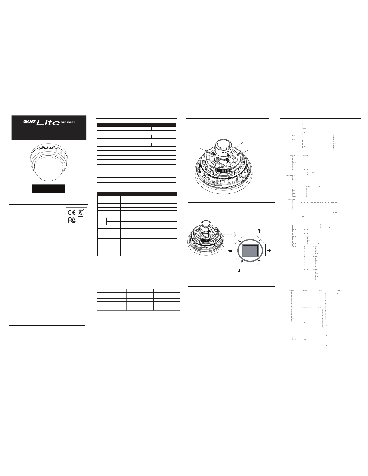
Camera Adjustments and Programming
In addition to the levelers for Focus (A) and Field of View (B),
all settings are made by keys on the OSD control bank. Alternatively, you may connect
to an external OSD menu control board.
Depending on the application, it may be required to set the unit for the proper video
standard. Please refer to Camera OSD Menu for required adjustment.
1. With power applied to the camera and a video monitor connected, press and hold
the MENU key for three seconds to access the top level menu. A map of the menu
options are shown in the following Camera OSD Menu.
2. Use the arrow keys on the control board to navigate around the OSD menu and use the
MENU key to confirm your selections. Once all the desired settings have been made,
confirm the changes be selecting SAVE and pressing the MENU key, otherwise any changes
made will be lost when the camera is next reset or has its power cycled.
3. To quit the exit the OSD menu without making any changes, select CANCEL
and press the MENU key.
4. If required, the camera can be reset to factory defaults by selecting
DEFAULT in the OSD menu.
.tcudorp siht gnisahcrup rof uoy knahT
.ylluferac teehs siht daer esaelp ,tinu siht gnitarepo erofeB
,ecnailpmoc yrotaluger ,stnetnoc egakcap edulcni teehs siht ni dedivorp noitamrofnI
pleh ot sa os no os dna snoitartsulli aremac ,snoitacificeps snel,snoitacificeps aremac
dna snoitacificeps eht taht eton esaelP .tinu siht tuoba retteb wonk uoy
stnemevorpmi rehtruf rof egnahc ot tcejbus era tinu si
ht fo ecnaraeppa
teehS siht tuobA
eht ot refer esaelp ,noitacificeps s’tinu eht tuoba snoitpircsed deliated roF
.relaed lacol ruoy tcatnoc esaelp ,yriuqni ro noitamrofni yna roF .tnetnoc gniwollof
without prior notice.
ecnailpmoC yrotalugeR
uneM DSO aremaC
Emissions FCC part 15 Class B
CE: EN55011
ICES-003
EN55022
CISPR 11
CISPR22
ANSI C63.4
Immunity CE: EN50130-4
RoHS
FCC COMPLIANCE:
This equipment has been tested and found to comply with the limits for a Class B digital device, pursuant to Part 15 of the
FCC Rules. These limits are designed to provide reasonable protection against armful interference in a residential installation.
This equipment generates uses and can radiate radio frequency energy and, if not installed and used in accordance with the
instructions, may cause harmful interference to radio communications. However, there is no guarantee that interference will
not occur in a particular installation.
If this equipment does cause harmful interference to radio or television reception, which can be determined by turning the
equipment off and on, the user is encouraged to try to correct the interference by one or more of the following measures:
• Reorient or relocate the receiving antenna.
• Increase the separation between the equipment and receiver.
• Connect the equipment into an outlet on a circuit different from that to which the receiver is connected.
• Consult the dealer or an experienced Radio/TV technician for help.
CISPR 22 WARNING:
This is a Class B product. In a domestic environment this product may cause radio interference in which case the user may be
required to take adequate measures.
POWER SUPPLY REQUIREMENTS:
For use with listed Audio/Video product and only connected to 15W or less power supply.
*Power supply should be a NEC Class 2 / LPS Supply.
EQUIPMENT MODIFICATION CAUTION:
Equipment changes or modifications not expressly approved by seller.
The party responsible for FCC compliance could void the user’s authority to operate the equipment and could create a
hazardous condition.
This class B digital apparatus complies with Canadian ICES-003.
Cet appareil numérique de la classe B est conforme à la norme NMB-003 du Canada.
V531-DF016-C03
Ver.09/2012
stnemtsujdA aremaC
.snoisrev RDW ot elbaliava ,)D( lortnoC draoB ecivreS setartsulli gniwollof ehT
ro snottub gnimmargorp eseht gnisu yb edam eb nac stnemtsujda aremaC
A
B
C
D
A: Focus Adjuster
B: Field of View Adjuster
C: Service Jack Socket
D: Service Board Control
esaB aremaC RDW setartsulli gniwollof ehT
.serutaef elbaliava dna
•
•
•
•
•
•
•
•
Quick install adaptor x 1
Torx driver x 1
D5 fixing screws x 3
T6 fixing screw (for T6 fixing screw) x 1
Wall plugs x 3
Power lead x 1
Cable entry sealing plug
(1/2”, for quick install adaptor use) x 1
Cable entry sealing plug
(3/4” ,for dome base use) x 1
service jack, alternatively.
RIGHT
LEFT
UP
DOWN
nsoitacificepS sneL
nsoitacificepS aremaC
Focal Length
F-No.
Iris Range
Minimum Object Distance
Field Of View
Diagonal
Horizontal
Vertical
3~9mm
116.2º~39.7º
90.0º~31.8º
66.2º~23.9º
F1.2
F1.2~F360
0.5m
F1.6
F1.6~F360
0.5m
92.8º~39.4º
71.0º~31.6º
51.6º~23.6º
4~9mm
GANZ Lite LDB series
EXIT
HLC
EXT
D/N Delay
N/D Level
N/N Delay
Return
Burst Off/On
IR Smart Off/On
IR Level
Return
On
IR Gain
Height
Width
Left/Right
Top/Bottom
Exposure Shutter 1/50, FLK, 1/250, 1/500, 1/1000, 1/2000,
Brightness
AGC Off/Low/Middle/High
DWDR Off
On Level
Return
1/4000, 1/5000, 1/10000, 1/100000, AUTO
Video (Only for CR)
Color Temp
Blue
Red
Return
Ret/End
Manual/Indoor/Outdoor
Level
Mode
Return
Ret/End
All Day/ Night Only
Area Sel.
Area State
Gain
Height
Width
Left/Right
Top/Bottom
Return
Ret/End
Area 1~2
Off/On
Image Adj. Lens Shad. Off/On
2DNR Off/On
Mirror Off/On
Font Color
Contrast
Font
ID & Title
On
Level
Return
Ret/End
Return Ret/End
Sharpness
Display CRT
Ped Level
Color Gain
Return
Ret/End
LCD
Gamma
Ped Level
Color Gain
Return
Ret/End
User Gamma
Ped Level
Color Gain
Return Ret/End
Neg. Image Off/On
Return Ret/End
Special Cam title Off/On
Motion
Privacy
DPC
On
input 0~9/A~Z etc.
Version
Return
Area Sel.
Area State
Height
Width
Left/Right
Top/Bottom
View
Off/On
Area 1~4
Off/On
Degree
Return
Ret/End
Off/On
On
Ret/End
Day/Night
Auto
D/N Level
Color
B/W
Lens
DC
White balance
AWC--Set
ATW1
ATW2
Manual
Backlight Off
BLC
Area Sel.
Area State
Height
Width
Left/Right
Top/Bottom
Area 1~8
Off/On
Color
Return
Ret/End
Off/On On
Reset Factory Reset
High/Low
Language
English/
中文
Return
Ret/End
Manual
CLR/Pos/End
Return
Ret/End
TV System
Image Sensor
Resolution
Scanning Frequency
Effective Picture Element
Video Output
S/N Ratio
Min. Illumination
Storage Temperature
Operating Temperature
Power Consumption
Power Source
NTSC PAL
1/3” Interline CCD Sensor
768(H)x494(V) 752(H)x582(V)
2:1 Interlace
H:15734Hz V:59.9Hz
H:15625Hz V:50.0Hz
600TV Line
0.32 Lux (50 IRE, F=1.2, ACG Max)
>50dB
1.0Vpp 75Ω BNC unbalanced
12VDC ±10%
1.7 W Max
-10°C~+50°C
-20°C~+60°C
General Specifications
Lens Control
Backlight Compensation
AWB
White Balance Control
Digital Noise Reduction
AGC Control
Day & Night
Sharpness
Auto / Manual
2 Zones On, Off, HLC
Low / Middle / High / Off
ATW 1(2700~9700K) / ATW2 (2000K~20000K),
2700k~9700k
Functional Specifications
Standard Range
EX Range
On / Off
2000k~20000k
Level 1-31
Auto/ Adjustable
On / OffMirror
Motion Detection
4 Zones On/Off
WDR Preference
On / Off
AWC / MANUAL
Shutter Function
Privacy Zone
8 Zones On/Off
MES 1/60, FLK, MES 1/50, FLK,
1/250~1/100000, Auto 1/250~1/100000, Auto
Surface mount (In a wall or ceiling)
Installation
Precautions
Do not attempt to dismantle the camera module mounted
within the dome. There are no user serviceable parts within the
camera module. Refer servicing to qualified personnel.
Handle the camera with care. Do not abuse the camera.
Avoid striking or shaking it. Improper handling and storage
could damage the camera.
Do not operate the camera beyond its temperature,
humidity or power source rating. Please refer to the
environmental information provided overleaf.
FCC COMPLIANCE: This equipment complies with Part 15 of
the FCC rules for intentional radiators and Class B digital devices
when installed and used in accordance with the instruction manual.
Following these rules provides reasonable protection against harmful
interference from equipment operated in a commercial area.
This equipment should not be installed in a residential area as
it can radiate radio frequency energy that could interfere with
radio communications, a situation the user would have to fix at their
own expense.
Emissions
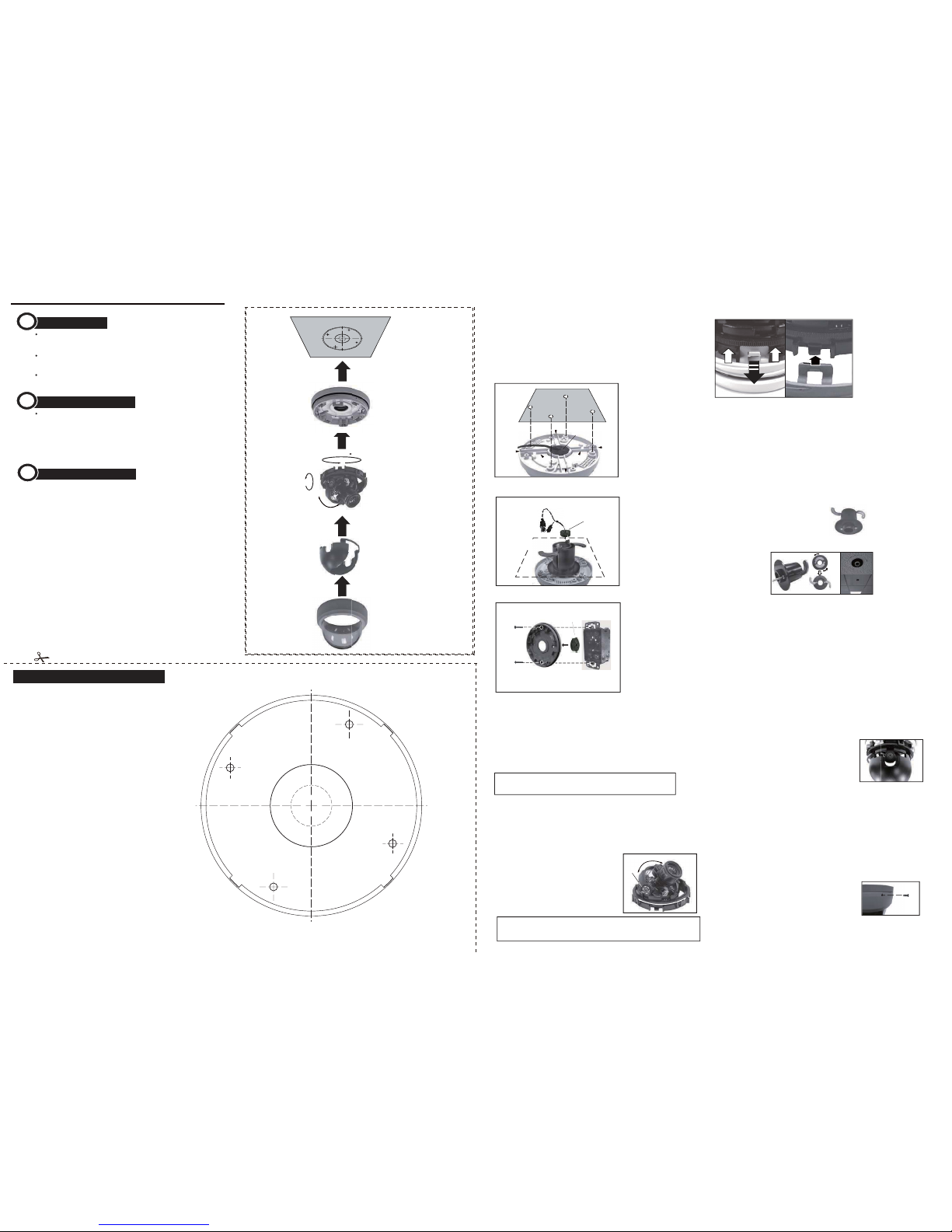
Template
A. By using the base mounting holes
B. By using the quick install adaptor
Install Methods
T1
T2
Side Knock-out
Side Knock-out
Side Knock-out
Side Knock-out
Cable Access
T1
T1
T1
Quick Install Adaptor
Replace the dome cover
Replace the dome cover and rotate clockwise to close it (as shown in image 5).
Mount the dome enclosure
By using the base mounting holes, the dome base can be fixed on the wall or
ceiling with attached screws.
Note: When using Quick Install Adaptor, re-assemble the parts of dome, then
mount the whole dome onto adaptor (see image B).
2.
3.
4.
5.
6.
Install the camera liner
Carefully fit the camera liner over the camera base so
that it snaps into place (as shown in image 4), and do
not obstruct the camera lens.
Tighten the tamper-proof screw
Use the supplied torx driver and the tamperproof screw (T2x5L) to secure the dome
cover.
Locking Arms
Install Quick Install Adaptor on indoor ceiling
Install the Dome Liner on
the Camera Module
Install camera module
Push the video-power cables through the opening
Feed the pre-connected video-power cables through the appropriate point. Then push the
cable out of the opening. Make sure the cable is positioned on the proper location and
out of the side knock-out, if required.
Note: Do not attempt to adjust the camera position by holding the lens as this will cause
damage to the camera.
Make adjustments by tilting and rotating the gimble assembly.
Adjust the camera position
To adjust the tilt angle, first loosen the 2 screws
on the gimble (See image right) make your
adjustments then retighten the screws.
The focus and range of the lens can be adjusted
(depending on the lens, see instructions
overleaf).
Screw
Gimble
Gimble
C
Video-Power Cables
B
Using the base mounting holes:
When mounting the dome to a ceiling or wall using screws, first knock out the screw
access holes that correspond to the template !marks “T1”.This can be done by using a
cross-point screwdriver.
Push the cables through the dome base and 3/4” rubber grommet.
Install the grommet on the base to prevent dust ingress. Cables may be routed through
the mounting surface if an appropriate hole is made at location T2.
If using the side knock-out, make sure the video-power cables are properly arranged in
the cable notch and exit out of the side knock without being crushed (see image A).
Using the Quick Install Adaptor(Optional):
When mounting the dome to a ceiling using the quick install adaptor, use
the template to cut a hole as the circle marked “T2” with a hole cutter.
Install the adaptor into the mounting surface and use the screws to adjust
the position of the two locking arms on the quick install adaptor to adjust
to the mounting surface.
Push the cables through the opening and 1/2”
rubber grommet. Make sure the grommet is
properly installed on the adaptor to prevent
dust ingress (see image B).
Mount on a US Single Gang Box:
When mounting the dome to the box, carefully remove the screws on the box.Install the 3/4“
grommet on the base to prevent dust ingress, then push the cables through the dome base
and 3/4” rubber grommet.
Mount the dome base on the box and reinstall the two screrws.
Tighten the screws sufficiently on the box (position T1, see image C).
Removing the dome cover and the camera liner
Gently turn the dome cover counter-clockwise to unlock and pull free of the dome base.
Remove the camera liner by gently pulling it free of the 4 notches in the camera base (see
image A).
Opening the required knock-out panel
Open one of the side knock-outs (see image A) to the size required to allow cable entry.
A.
B.
C.
US Single Gang Box
Dome Base
T1
T1
Mount on a pre-installed US Single Gang Box
3/4”
Rubber Grommet
1/2”Rubber Grommet
Mount with the Quick Install Adaptor
Side
Knock-outs
Mounting Surface
Mount with the Dome Base
Cable Notch
Cable Notch
3/4”
Rubber Grommet
A
PULL
Preparation before installation
Use the template (see overleaf) to mark-out and prepare the mounting area.In
order to mount the base, first remove the camera module by gently pulling down
on the tabs that hold the camera module in place (see image right) and remove
camera assembly. To re-assemble gently pull down on the tabs and insert the
camera assembly.
1.
Loosen the tab and pull out the camera assembly
Tighten tamper-proof
screw
Tamper-proof Screw
2
3
4
5
Dome Base
Camera Module
Camera Liner
Dome Cover
T2
1
ROTATE 360°
PAN 360°
TILT 90°
T1
T1
T1
T1
Mounting Surface
When the cables are threaded through the mounting surface,
create an apture indicated “T2”. It can be simply threaded for
use with the quick install adapter .
When mounting the dome on a surfce with the four T1 screws,
use one of the side knock-outs as indicated for cable entry
(see Installation Guide overleaf ).
Using Quick Install Adaptor:
Create an aperture in the mounting surface to a diameter of
1.5” (38mm) as indicated by “T2”.
The aperture is also avaliable for cable access (3/4”, 19mm).
Using screws:
Create four holes at template positions ‘T1’, use the screws
and plugs provided in the screw kit where the mounting
surface is appropriate.
 Loading...