

Page 1
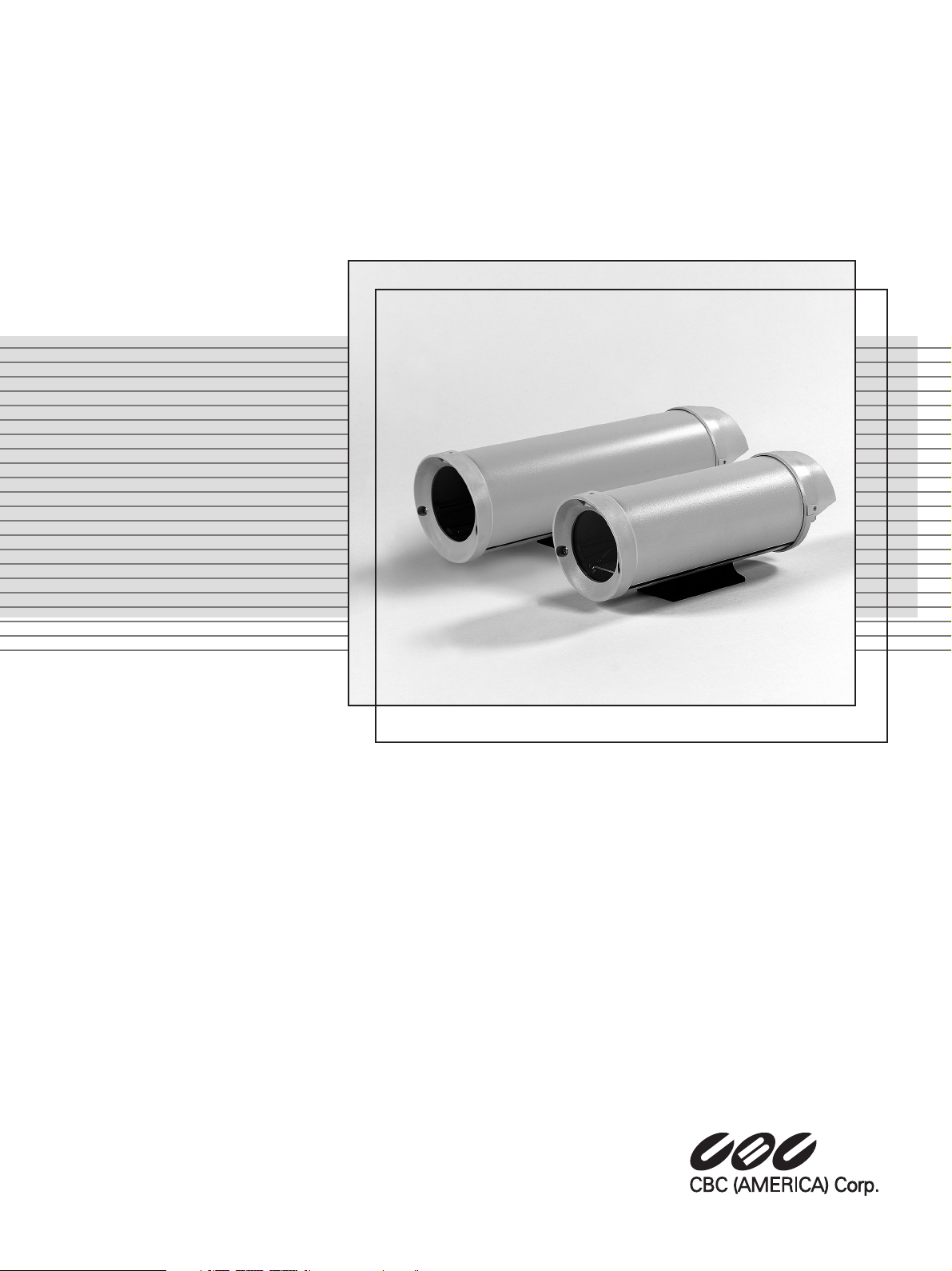
Instructions for Use
H Series Housings
Page 2

2
IMPORTANT SAFEGUARDS
1. Read Instructions - All the safety and operating instructions should be read
before the unit is operated.
2. Retain Instructions - The safety and operating instructions should be
retained for future reference.
3. Heed Warnings - All warnings on the unit and in the operating instructions
should be adhered to.
4. Follow Instructions - All operating and use instructions should be followed.
5. Cleaning - Unplug the unit from the outlet before cleaning. Do not use
liquid cleaners or aerosol cleaners. Use a damp cloth for cleaning.
6. Attachments - Do not use attachments not recommended by the product
manufacturer as they may cause hazards.
7. Accessories - Do not place this unit on an unstable stand, tripod, bracket,
or mount. The unit may fall, causing serious injury to a person and serious
damage to the unit. Use only with a stand, tripod, bracket, or mount
recommended by the manufacturer or sold with the product. Any
mounting of the unit should follow the manufacturer's instructions and
should use a mounting accessory recommended by the manufacturer.
An appliance and cart combination should be moved with care. Quick
stops, excessive force, and uneven surfaces may cause the appliance and cart
combination to overturn.
8. Ventilation - Openings in the enclosure, if any, are provided for ventilation,
to ensure reliable operation of the unit, and to protect it from overheating.
These openings must not be blocked or covered. This unit should not be
placed in a built-in installation unless proper ventilation is provided or the
manufacturer's instructions have been adhered to.
9. Power Sources - This unit should be operated only from the type of power
source indicated on the marking label. If you are not sure of the type of
power supply you plan to use, consult your appliance dealer or local power
company. For units intended to operate from battery power or other
sources, refer to the operating instructions.
10. Grounding or Polarization - This unit may be equipped with a polarized
alternating-current line plug (a plug having one blade wider than the other).
This plug will fit into the power outlet only one way. This is a safety
feature. If you are unable to insert the plug fully into the outlet, try
reversing the plug. If the plug should still fail to fit, contact your electrician
to replace your obsolete outlet. Do not defeat the safety purpose of the
polarized plug.
Alternately, this unit may be equipped with a 3-wire grounding-type plug, a
plug having a third (grounding) pin. This plug will only fit into a
grounding-type power outlet. This is a safety feature. If you are unable to
insert the plug into the outlet, contact your electrician to replace your
obsolete outlet. Do not defeat the safety purpose of the grounding-type
plug.
11. Power Cord Protection - Power supply cords should be routed so that they
are not likely to be walked on or pinched by items placed upon or against
them, paying particular attention to cords and plugs, convenience
receptacles, and the point where they exit from the appliance.
12. Power Lines - An outdoor system should not be located in the vicinity of
overhead power lines or other electric light or power circuits or where it can
fall into such power lines or circuits. When installing an outdoor system,
extreme care should be taken to keep from touching such power lines or
circuits as contact with them might be fatal. U.S.A. models only - refer to the
National Electrical Code Article 820 regarding installation of CATV systems.
13. Overloading - Do not overload outlets and extension cords as this can result
in a risk of fire or electric shock.
14. Object and Liquid Entry - Never push objects of any kind into this unit
through openings, as they may touch dangerous voltage points or short out
parts that could result in a fire or electric shock. Never spill liquid of any
kind on the unit.
15. Servicing - Do not attempt to service this unit yourself as opening or
removing covers may expose you to dangerous voltage or other hazards.
Refer all servicing to qualified service personnel.
16. Damage Requiring Service - Unplug the unit from the outlet and refer
servicing to qualified service personnel under the following conditions:
a. When the power supply cord or plug is damaged.
b. If liquid has been spilled or objects have fallen into the unit.
c. If the unit has been exposed to rain or water.
d. If the unit does not operate normally by following the operating
instructions. Adjust only those controls that are covered by the
operating instructions, as an improper adjustment of other controls
may result in damage and will often require extensive work by a
qualified technician to restore the unit to its normal operation.
e. If the unit has been dropped or the cabinet has been damaged.
f. When the unit exhibits a distinct change in performance--this indicates
a need for service.
17. Replacement Parts - When replacement parts are required, be sure the
service technician has used replacement parts specified by the manufacturer
or have the same characteristics as the original part. Unauthorized
substitutions may result in fire, electric shock, or other hazards.
18. Safety Check - Upon completion of any service or repairs to this unit, ask
the service technician to perform safety checks to determine that the unit is
in proper operating condition.
19. Coax Grounding - If an outside cable system is connected to the unit, be
sure the cable system is grounded. U.S.A. models only--Section 810 of the
National Electrical Code, ANSI/NFPA No.70-1981, provides information
with respect to proper grounding of the mount and supporting structure,
grounding of the coax to a discharge unit, size of grounding conductors,
location of discharge unit, connection to grounding electrodes, and
requirements for the grounding electrode.
20. Lightning - For added protection of this unit during a lightning storm, or
when it is left unattended and unused for long periods of time, unplug it
from the wall outlet and disconnect the cable system. This will prevent
damage to the unit due to lightning and power line surges.
Page 3
3
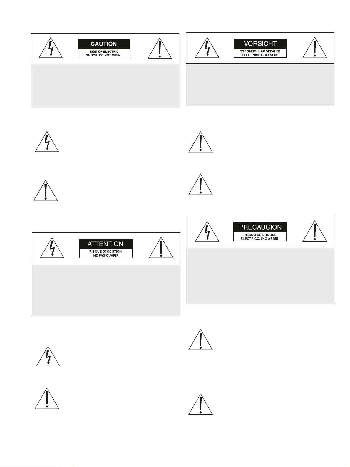
SAFETY PRECAUTIONS
This label may appear on the bottom of the unit due to space
limitations.
The lightning flash with an arrowhead symbol
within an equilateral triangle is intended to alert
the user to the presence of uninsulated
"dangerous voltage" within the product's
enclosure that may be of sufficient magnitude to
constitute a risk of electric shock to persons.
The exclamation point within an equilateral
triangle is intended to alert the user to presence
of important operating and maintenance
(servicing) instructions in the literature
accompanying the appliance.
SECURITE
En raison de limitation de place, cette étiquette peut être placée
sur le dessous de l'appareil.
L'éclair fléché dans un triangle équilatéral, avertit
l'utilisateur de la présence d'une "tension
dangereuse" non isolée à l'intérieur de l'appareil et
d'une valeur suffisante pour constituer un risque
d'électrocution.
Le point d'exclamation contenu dans un triangle
équilatéral, avertit l'utilisateur de la présence, dans
la documentation qui accompagne l'appareil, de
consignes d'utilisation et de maintenance
importantes.
SICHERHEITSVORKEHRUNGEN
Aus Platzgründen kann diese Warnung auf der Unterseite des
Gerätes angebracht sein.
Das Blitzsymbol im gleichseitigen Dreieck soll
den Benutzer auf nicht isolierte "Hochspannung"
im Gehäuse aufmerksam machen, die eventuell
stark genug ist, um einen elektrischen Schlag zu
verursachen.
Das Ausrufezeichen im gleichseitigen Dreieck soll
den Benutzer auf wichtige Bedienungs- und
Wartungsanleitungen in der dem Gerät
beigefügten Literatur aufmerksam machen.
PRECAUCIONES DE SEGURIDAD
Debido a limitaciones de espacio, esta etiqueta puede aparecer
en la parte inferior de la unidad.
El símbolo representado por un relámpago con
punta de flecha dentro de un triángulo equilátero,
se muestra con el objetivo de alertar al usuario que
existen "voltages peligrosos" sin aislamiento,
dentro de la cubierta de la unidad. Dichos
voltages pueden ser de tal magnitud que
constituyen un riesgo de choque eléctrico a
personas.
El símbolo de exclamación dentro de un triángulo
equilátero, se muestra con el objetivo de alertar al
ususario de que instrucciones de operación y
mantenimiento importantes acompañan al equipo.
CAUTION: TO REDUCE THE RISK OF
ELECTRICAL SHOCK, DO NOT OPEN COVERS.
NO USER SERVICEABLE PARTS INSIDE. REFER
SERVICING TO QUALIFIED SERVICE
PERSONNEL.
DANGER: POUR ÉVITER TOUT RISQUE
D'ÉLECTROCUTION, NE PAS OUVRIR LE
BOÎTIER. IL N'Y A PAS DE PIÈCES
REMPLAÇABLES À L'INTÉRIEUR. POUR
TOUTE RÉVISION, S'ADRESSER À UN
TECHNICIEN SPÉCIALISÉ.
VORSICHT: UM EINEN ELEKTRISCHEN
SCHLAG ZU VERMEIDEN, ABDECKUNG
NICHT ENTFERNEN. WARTUNGEN ALLER
ART QUALIFIZIERTEM PERSONAL
ÜBERLASSEN.
PRECAUCION: PARA REDUCIR EL RIESGO DE
CHOQUE ELÉCTRICO, FAVOR NO ABRIR LA
CUBIERTA. ESTE EQUIPO NO CONSTA DE
PIEZAS O PARTES QUE REQUIEREN SERVICIO
O MANTENIMIENTO. PARA REPARACIONES
FAVOR REFERIRSE A UN TÉCNICO
CALIFICADO.
Page 4

4
CONTENTS
1 UNPACKING . . . . . . . . . . . . . . . . . . . . . . . . . . . . .4
2 ACCESSORIES . . . . . . . . . . . . . . . . . . . . . . . . . . . .4
2.1 Sunshields . . . . . . . . . . . . . . . . . . . . . . . . . . . . . . . . .4
2.2 Tamper Proof Kit . . . . . . . . . . . . . . . . . . . . . . . . . . .4
3 SERVICE . . . . . . . . . . . . . . . . . . . . . . . . . . . . . . . . .4
4 CARE AND MAINTENANCE . . . . . . . . . . . . . . .4
5 DESCRIPTION . . . . . . . . . . . . . . . . . . . . . . . . . . .4
6 INSTALLATION . . . . . . . . . . . . . . . . . . . . . . . . . .4
6.1 Model Designation . . . . . . . . . . . . . . . . . . . . . . . . . .4
6.2 Maximum Camera/Lens Size . . . . . . . . . . . . . . . . . .4
6.3 Tools Required . . . . . . . . . . . . . . . . . . . . . . . . . . . . .4
6.4 Cable Requirements . . . . . . . . . . . . . . . . . . . . . . . . .5
6.5 Housing Mounting . . . . . . . . . . . . . . . . . . . . . . . . . .5
6.6 Cover Removal . . . . . . . . . . . . . . . . . . . . . . . . . . . . .5
6.7 Camera/Lens Installation . . . . . . . . . . . . . . . . . . . . .5
6.8 Camera/Lens Wiring . . . . . . . . . . . . . . . . . . . . . . . .6
6.9 Video Coax Connection . . . . . . . . . . . . . . . . . . . . . .7
6.10 Lens Wiring . . . . . . . . . . . . . . . . . . . . . . . . . . . . . . .7
6.11 Camera/Lens Adjustment . . . . . . . . . . . . . . . . . . . . .7
6.12 Final Assembly . . . . . . . . . . . . . . . . . . . . . . . . . . . . .7
6.13 Fuse Replacement . . . . . . . . . . . . . . . . . . . . . . . . . . .8
7 EXPLODED VIEW . . . . . . . . . . . . . . . . . . . . . . . . .8
7.1 Parts List . . . . . . . . . . . . . . . . . . . . . . . . . . . . . . . . .8
1 UNPACKING
Unpack carefully. This is mechanical equipment and should be
handled with care.
Check for the following:
n Housing (with correct model number).
n Hardware Kit - H-1 & H-2 Models:
1 1/4-20 x 3/8-in Button Head Screw.
2 1/4-20 x 1/2-in Button Head Screw.
2 1/4-in Spring Washers.
1 5/16-in Flat Washer.
2 Fittings, 3/8-in NPT.
2 Rubber Plug, 1/2-in NPT.
1 Nut, 3/8-in NPT.
2 Fittings, 1/2-in NPT.
2 Nut, 1/2-in NPT.
1 Spacer Block.
If an item appears to have been damaged in shipment, replace it
properly in its carton and notify the shipper. If any items are
missing, contact the company from which the unit was purchased.
The shipping carton is the safest container in which the unit
may be transported. Save it for possible future use.
2ACCESSORIES (Optional)
2.1 Sunshields
Provides protection from the direct rays of sun and promotes
cooling to reduce internal housing temperatures. Strongly
recommended for housing to be used outdoors.
SS1: For H-1 & H-2 Series Housings.
2.2 Tamperproof Kit
Contains tamper resistant screws and bit key to tamperproof up
to five housings.
TPK 1: For all H Series Housings.
3 SERVICE
If the unit ever needs repair service or parts, the customer
should contact the company from which the unit was purchased
for authorization to return and shipping instructions.
4 CARE AND MAINTENANCE
Regularly scheduled maintenance will help prolong the
operation life of this unit. Clean the viewing window as needed
with a mild, nonabrasive detergent in water and a soft cloth.
5 DESCRIPTION
The H Series Housings are smart stylized housings for indoor
and outdoor use. These housings meet customers' demands for
an attractive housing that is both cost competitive and easy to
install.
6 INSTALLATION
This installation should be made by qualified service personnel
and conform to the National Electrical Code and applicable
local codes.
6.1 Model Designation
Model Description Voltage Use with Camera
No. Models with These
Voltage Ranges
H-1 Housing ----- 24 VAC or 12 VDC
H-2 Housing with heater
1
24/23 24 VAC
H-3 Housing w/heater/blower 24/25 24 VAC
1. The heater operates at 24 VAC, 50/60 Hz and requires 15 W of power.
Do Not Exceed 30 VAC Input on 24 VAC models. Operation
above 30 VAC violates low voltage operation (Class 2
Specifications). Normal operation is 24 VAC.
TUV Approved 24 VAC Models
Caution: Use an approved power supply incorporating
reinforced insulation from primary to secondary to isolate unit
from Mains.
6.2 Maximum Camera/Lens Size
H-1: 68 W x 54 H x 197 L mm (2.68 x 2.1 x 7.75 in)
H-2: 68 W x 54 H x 197 L mm (2.68 x 2.1 x 7.75 in)
H-3: 71 W x 71 H x 229 L mm (2.8 x 2.8 x 9)
6.3 Tools Required
- Small flat blade screwdriver.
- Phillips screwdriver (P2).
- Adjustable wrench.
- Wire cutter/stripper/crimper tool.
- 5/32-in (or 4 mm) hex wrench.
Page 5

5
6.4 Cable Requirements
Video Transmission (Coaxial)
Cable Type: RG-59/U for runs < 300 m (1000 ft).
RG-11/U for runs < 600 m (2000 ft).
Cable Size: Outside diameter between
4.6 mm (0.181-in) - 7.9 mm (0.312-in).
Cable Shape: Round.
Shield: > 93% Braided Copper Shield.
Center Conductor: Stranded Copper Center.
DC Resistance: < 15 Ohms/1000 (RG-59/U).
< 6 Ohms/1000 (RG-11/U).
Cable Impedence: 75 Ohm.
Agency Rating: UL.
Environmental: Outdoor rated.
Temperature Rating: > 80 °C.
Sources: Belden 9259.
Belden 9238.
Input Power Cord - North American
Cable Type: SJTOW-A rated.
Cable Size: Outside diameter between
4.3 mm (0.170 in) - 11.9 mm (0.470 in).
Cable Shape: Round.
Conductors: 3 conductor version and
2 conductor version.
Agency Rating: UL/C.S.A., UL VW-1.
Environmental: Outdoor rated.
Temperature Rating: 105 °C.
Voltage Rating: 300 V.
Sources: Belden 19506.
Belden 19509.
Northwire 573939.
Input Power Cord - European
Cable Type: H05RN-F3G0.75 and
H05RN-F3G1.00.
Cable Size: Outside diameter between
4.3 mm (0.170 in) - 11.9 mm (0.470 in).
Cable Shape: Round.
Conductors: 3 conductor version and
2 conductor version.
Agency Rating: VDE.
Environmental: Outdoor rated.
Sources: Olflex 1600252.
Olflex 1600253.
Lens Control Cable
Cable Type: Jacketed Multiconductor Cable.
Cable Size: Outside diameter between
4.3 mm (0.170 in) - 11.9 mm (0.470 in).
Cable Shape: Round.
Shield: Overall shielding.
Conductors: Stranded 20 to 16 AWG wire.
No. of Conductors: 4 and 8.
Conductor
Insulation: Color coded.
Sources: Belden 9552.
Belden 9554.
6.5 Housing Mounting
1. Use the two 1/4-20 x 0.50-inch screws and 1/4-in spring
washers provided in the hardware kit to mount the housing
to a mount or a pan/tilt. The spring washers must be used
for the screws to thread properly.
2. The outer most set of 1/4-20 threaded holes are for
mounting to feed-through mounts and the inner most 1/420 holes are for mounting to all other mounts and pan/tilts.
6.6 Cover Removal
1. Loosen the top two screws on the rear of the housing. These
screws are captive and will not come out all the way. Do not
remove the bottom two screws. See Figure 1.
Figure 1: Loosening Captive Screws
2. Grasp the housing's front cap and pull forward. Do not
squeeze the cover itself. This will make it difficult to slide off
the cover. See Figure 2.
Figure 2: Removing the Cover
3. The cover is attached to the base. Allow the cover to dangle
from the base.
6.7 Camera/Lens Installation
1. Loosen the two screws holding the camera bracket to the
base. It is not necessary to remove them completely. See
Figure 3.
Loosen These Screws
Do Not Remove
Grasp Here
Page 6

6
Figure 3: Removing the Camera Bracket
2. Remove the camera bracket from the base. If you are using
the feed-through feature, refer to section 6.8.3 at this time.
Mounting fixed lens cameras in H Series Housings
3a. Attach the lens to the camera.
3b. Use the 1/4-20 x 3/8-inch screw to mount the camera to the
camera bracket. The lens should extend approximately 6
mm (0.25-in) from the front of the camera bracket. See
Figure 4.
Figure 4: Attaching the Camera
6.8 Camera/Lens Wiring
WARNING: Only use the cables specified under
"INSTALLATION, Cable Requirements" for wiring
of all cameras and lenses.
6.8.1 Fittings
1. The two large 1/2-in NPT fittings accept round cable with
diameters from 4.3 mm (0.17-in) to 11.9 mm (0.47-in). The
small fittings will accept cables with diameters from 4.6 mm
(0.181-in) to 7.9 mm (0.312-in).
Be sure to securely tighten all fittings to ensure a
liquid-tight seal. Failure to do so could allow water to
enter the housing and damage the camera and lens.
If a sealant is to be used, be sure it is a neutral cure type.
Sealants that release acetic acid may harm camera electronics.
Use of "drip loops" is recommended on the wiring
outside of the rear end cap.
6.8.2 Conduit
These housings are designed to allow conduit to be directly
connected.
1. Remove the rear fittings and attach the conduit and conduit
fittings directly to the housing rearcap. The holes accept
1/2-in conduit fittings and PG 13.5 conduit fittings. Any
unused holes can be covered using the plugs provided in the
hardware kit.
6.8.3 Feed-through Wiring
These housings have the capability of having the cabling feed
through the foot of the housing. This requires the use of feedthrough mounts like the WB-1, WB-2, & JB-1.
1. Prior to mounting the camera. Remove the two dome plugs
located inside the housing. See Figure 5.
Figure 5: Feed-through Wiring
2. Screw the two 3/8-in NPT fittings into the foot of the
housing.
3. Pull the cabling through the fittings and into the housing.
Tighten the fitting to 4.0 N-m to 4.5 N-m (35 in-lb to
40 in-lb). This torque rating is approximately 1 to 1 1/2
turns past the point the fitting starts to grip the wire. Failure
to do so will result in water damage to all electronic parts.
4. Attach top bracket of the mount to the foot of the housing.
5. Cover the holes in the rear cap with the rubber plugs
provided. Push in until flush and then release.
Camera
Bracket
Loosen These
Screws
1/4-20 ¥ 3/8 Screw
6.4 mm
0.25 in
Camera Bracket
Camera
Remove These
Dome Plugs
3/8-inch
NPT Fitting
Foot
1/2-inch
Rubber Plugs
Rear Cap
Page 7

7
6.8.4 Power Connections
Power connection into the housings is to be supplied through a
minimum type UL Standard "SJ" cord acceptable for outdoor
use. Installation must conform to acceptable NEC and local
codes. For 24 volt cameras, use the chart below for selecting the
proper wire size.
Recommended Maximum Cable Lengths for Housings
Equipped with 24 Volt Cameras, Heaters, and Blowers
Wire Size Housing Distance
mm2AWG meters feet
0,5 20 28.6 94
118 45.7 150
1,5 16 70.1 230
2,5 14 115.5 379
412 183.8 603
610 292.6 960
10 8 464.2 1523
Note: The use of wire sizes larger than 1,5 mm2(14 AWG) will require a
splice in order to accomodate the terminal block.
1. Install one of the large 1/2-in NPT fittings into one of the
holes in the rear cap. The terminal block side is preferable. If
you are using the feed-through option, ignore this step.
2. Route the power cable through the fitting in the rear cap or
one of the feed-through fittings in the foot.
3. The terminal block provided on H-1 & H-2 units accepts
wire ranging from 20 to 14AWG or 1.5 mm2. The terminal
block provided on /H-3 units accepts wire ranging from 18
to 12AWG or 2.5 mm2. When using larger wire sizes, splice
to a smaller size wire at the terminal block end. The splice
may need to be enclosed in a junction box if it does not pass
through the fittings.
4. On heater and heater/blower units, make sure the heater and
fan wires stay connected to the terminal.
5. A screw/terminal lug is provided for securing a safety
ground. To attach the safety grounding wire (green 115 volt,
green/yellow 230 volt), first unscrew the terminal lug and
strip and crimp the grounding wire into the lug. Attach the
terminal lug to the bracket using the M4 x 10 screw
provided (H-1 & H-2 models use an M4 Nut to screw the
lug to the base). See Figure 6.
Be sure to securley tighten all fitting s to ensure a liquid-tight
seal. Failure to do so could allow water to enter the housing
and damage the camera and lens.
6.9 Video Coax Connection
WARNING: Only use the cables specified under
"INSTALLATION, Cable Requirements" for wiring of
the video coax connection.
1. Install a 1/2-in NPT fitting into the remaining hole in the
rear cap.
2. Route the video coax cable through one of the fittings
installed in step 1 or one of the feed-through fittings in the
base.
3. Attach BNC connector to the coax and connect it to the
camera. Pull excess wire out of the housing and tighten the
fitting to 8.5 N-m to 9.0 N-m (75 in-lb to 80 in-lb). This
torgue rating is approximately1 to 1 1/2 turns past the point
the fittings starts to grip the wire. Failure to do so will
result in water damage to the electronic parts.
Be sure to securley tighten all fitting s to ensure a liquid-tight
seal. Failure to do so could allow water to enter the housing
and damage the camera and lens.
Use of “drip loops” is recommended on the wiring outside of
the rear end cap.
6.10 Lens Wiring
WARNING: Only use the cables specified under
"INSTALLATION, Cable Requirements" for wiring of
the lens.
Use of "drip loops" is recommended on the wiring outside of
the rear end cap.
1. Install the last 1/2-inch NPT fitting into the remaining hole
in the rear cap. Zoom lenses can only be installed into
H-3 housings.
Ground
Neutral
Line
Terminal Lug
Screw
Fuseholder
Figure 7: Power Connections - Fan Units
Neutral
Neutral
Terminal Lug
Terminal Lug
M4 Nut
M4 Nut
Line
Line
Figure 6: Power Connections - Nonfan units
Page 8

2. If installing a zoom lens, insert the lens control cable
through the last fitting at the rear of the housing. Attach the
lens wiring to the lens mating connector and connect it to
the lens. If mating connector is not available, connect
directly to the lens cable. Pull any excess wire out of the
housing and tighten the fitting to 8.5 N.m to 9.0 N.m
(75 in.lb to 80 in.lb). This torque rating is approximately 1
to 1-1/2 turns past the point where the fitting starts to grip
the wire. Failure to do so will result in water damage to all
electronic parts.
NOTE: See specification on lens cord for correct plug
connection.
Be sure to securely tighten all fittings to ensure a
liquid-tight seal. Failure to do so could allow water to
enter the housing and damage the camera and lens.
Use of "drip loops" is recommended on the wiring
outside of the rear end cap.
6.11 Camera/Lens Adjustment
1. Verify camera and lens operation before final assembly of
the cradle into the housing. Adjust the camera focus and
iris as necessary. See individual camera instructions.
6.12 Final Assembly
1. Use the plugs or fittings provided to plug any remaining
holes in the rear cap.
2. Reinstall the cover. Align the bottom of the cover ribs with the top of
the base. Slide the cover onto the base. Make sure the seal is not
folded over or torn. Use silicone grease to lubricate the seals if
necessary. See Figure 8.
3. As the cover nears the rear cap, make sure the captive screws
in the back are not blocking the cover from engaging into the
rear cap.
4. Screw the two rear captive screws into the housing.
6.13 Fuse Replacement
1. To replace a fuse, take a flat blade screw driver and twist
the top of the fuseholder counter clockwise about a ⁄ of a turn.
The fuse is spring loaded so it will eject.
2. Replace the fuse with a fuse that has the same current rating.
The fuse is a 5x20 mm slow blow cartridge type fuse.
Recommend using Littelfuse series 218.
See Detail
Detail Scale 2 : 1
Scale 3 : 1
Cover Rib
To p of Base
Seal
Figure 8: Reinstalling the Cover
6
5
4
3
2
1
7
7 EXPLODED VIEW
7.1 Parts List
Ref Drawing
No. Number Part Description
1 LTC 9480/20HTR 24VAC Heater Kit
2 315 3142 001 Camera Bracket Kit
3 315 3143 001 Foot Kit
6 315 3146 002 Rearcap Kit
7 315 3147 001 Base Kit
8 315 3148 004 Cover Kit
9 315 3149 001 Frontcap Kit
- 315 3062 001 Hardware Kit
©2002 CBC (America) Corp.
New York: 55 Mall Drive, Commack, NY 11725 Tel: 800 422 6707 or 631 864 9700 Fax: 631 543 5426
California: 20521 Earl Street, Torrance, CA 90503 Tel: 800 888 0131 or 310 793 1500 Fax: 310 793 1506
www.cbcamerica.com
Data subject to change without notice
100_0058_002 CBC
Printed in USA
8
Page 9

WB-1, JB-1, PMA-1
Feed-through Mounts
& Accessories
Instructions for Use
Page 10

SAFETY PRECAUTIONS
The exclamation point within an equilateral triangle is
intended to alert the user to presence of important operating and maintenance (servicing) instructions in the literature accompanying the appliance.
SECURITE
Le point d'exclamation à l'intérieur d'un triangle équilatéral avertit
l'utilisateur de la présence
d'instructions importantes d'utilisation et de
maintenance dans la documentation accompagnant
l'appareil.
SICHERHEITSVORKENHRUNGEN
Das Ausrufezeichen in dem gleichseitigen Dreieck ist dazu da, den
Benutzer auf wich-tige
Inbetriebnahme- und Instandhaltungs-vorschriften
hinzuweisen, die dem Gerät in Form einer Broschüre
beigelegt sind.
PRECAUCIONES DE SEGURIDAD
El símbolo de exclamación dentro de un triángulo equilátero, se muestra con el objetivo de alertar al ususario
de que instrucciones de operación y
mantenimiento importantes acompañan al equipo.
1UNPACKING
Unpack carefully. This is mechanical equipment and should be handled with care.
Check for the following items:
n Verify the unit model number.
n Instructions for Use.
If an item appears to have been damaged in shipment, replace it properly in its carton and notify the shipper. If any items are missing, contact the company from which the unit was purchased.
The shipping carton is the safest container in which the unit may be
transported. Save it for possible future use.
2SERVICE
If the unit ever needs repair service, the customer should
contact the company from which the unit was purchased for authorization to return and shipping instructions.
3DESCRIPTION
WB1 18-cm (7-in) and JB1 40-cm (15-in) Feed-through Mounts.
This indoor/outdoor mounting equipment is designed for fixed camera or camera housing installations up to 9 kg (20 lb) rated load.
These models are made of lightweight aluminum and feature welded
construction, providing an extremely rigid camera mount. These
brackets have been specifically designed for the H1 & H2 series
housings. All mounts come fully assembled.
4INSTALLATION
4.1 WB-1, JB-1
1. Determine a secure wall mounting location.
2
WARNING: All mounts are deisgned to support a load only
in a vertical direction. Mounts MUST be positioned as
shown under SPECIFICATIONS.
2.
Cautions:
a. For a secure installation, use four 8-mm (5/16-in) diameter
fasteners (not included). Use stainless steel or zinc plated
fasteners.
b. If bolts are used, they should extend through the mounting
surface and be secured with flat washers, lock washers, and
nuts on the opposite side. Each bolt must have a
minimum pull-out strength of 200 kg (450 lb).
c. If studs are used, they should be anchored in concrete or
welded to a steel backer plate. Each stud must have a minimum pull out strength of 200 kg (450 lb).
d. If the wall mount is attached to wood or to a blind
structure (with no access to the rear), each fastener
must have a minimum pull-out strength of at least 200 kg
(450 lb).
3. Locate the four holes or stud locations using the flange as a
template (four holes equally spaced on a 69.9-mm (2-3/4-in bolt
circle).
4. Feed wires through the large hole in the flange or through the
slot on the surface where the camera housing mounts.
5. Install the mount using bolts or studs at least 8-mm (5/16-in) in
diameter.
6. To mount the camera or camera housing:
a. Mount camera with a 1/4-20 bolt and lock washer (not
furnished) in the center hole of the adjustable head.
b. Mount housings with three 1/4-20 bolts and lock
washers (not furnished).
c. Lock mount head in position by using the supplied
1/8-inch long-arm hex wrench to tighten screws.
4.2 PMA-1 Pole mount Adapter
1. Tools required
8mm Hex Wrench
Banding Tool (PMA-1 recommended)
2. Mounting
1. Attach the bracket to the pole at the desired height using the
two straps and two buckles provided.
2. Tension the straps according to the instructions for the banding
tool. BAND-IT, Banding tool is recommended and may be purchased seperately. A BAND-IT Tool Instruction Chart is provided with each pole mount. Figure 1. shows how the ends of the
bands are bent around the buckle.
Figure 1: Banding Method
Tension and
Bend Back Bands
Bend Buckle
Tab Over Bands
Page 11

3
5SPECIFICATIONS
5.1 WB1 18-cm (7-in) Indoor/Outdoor
Feed-through Mount
Maximum Load: 9 kg (20 lb).
Mounting Head: Adjustable. 360° pan, 180° tilt.
Finish: Dark mushroom.
Approx. Weight: 0.3 kg (0.7 lb).
WARNING: All mounts must be mounted as shown.
WARNING: All mounts must be mounted as shown.
5.2 JB1 40-cm (15-in) Indoor/Outdoor
Feed-through J-mount
Maximum Load: 9 kg (20 lb).
Mounting Head: Adjustable. 360° pan, 180° tilt.
Finish: Dark mushroom.
Approx. Weight: 0.55 kg (1.2 lb).
WARNING: All mounts must be mounted as shown.
5.3 PMA-1 pole Mount Adapter
Maximum Load: 9kg (20lb)
Finish: Formed Aluminum Plate
Approximate Weight: 0.5kg (1lb)
3. Secure the wall mount to the pole mount using the four (4) 8mm
screws and lock washers provided.
WB-1 uses 8mm screws
Figure 2: Securing Model PMA-1
WB-1 Feed-through Mount
JB1 Feed-through J-mount
Pole Mount
0.31
12.7
0.50
7.9
23.9
0.94
88.9
3.50
73.2
2.88
25.4
1.00
37.3
1.47
74.7
2.94
6.9
0.27
Wall Mount
Buckle
Lock Washer
Screw
Band
8.9
0.35
391
15.4
179.8
7.08
88.9
3.50
157
6.2
234
9.2
mm
in
138.3
5.45
mm
in
Page 12

©2002 CBC (America) Corp.
New York: 55 Mall Drive, Commack, NY 11725 Tel: 800 422 6707 or 631 864 9700 Fax: 631 543 5426
California: 20521 Earl Street, Torrance, CA 90503 Tel: 800 888 0131 or 310 793 1500 Fax: 310 793 1506
www.cbcamerica.com
Data subject to change without notice
100_0059_002 CBC
Printed in U.S.A.
 Loading...