

Page 1
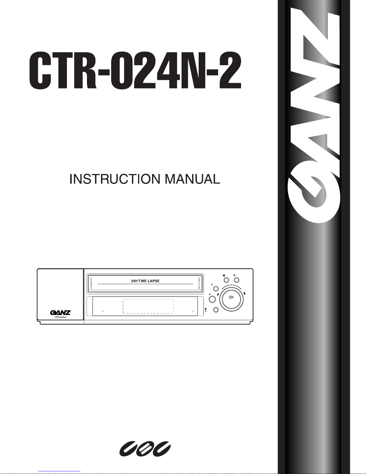
REV.
PLAY
P/STILL
PLAY
REC CHECK
/
POWER
REC
STOP
EJECT
ALARM
KEY
R
E
W
F
F
LOCK
V-POS
H-POS
FIELD ADVANCE
TIME/CNT
/REM
TIMER
REC/PLAY HOURS
ALARM
INDEX
MENU
COUNTER
ENTER
CLEAR
LOCK
SHARPNESS
ON OFF
SOFT HARD
TRACKING
CURSOR
DOWN
UP
VIDEO CASSETTE RECORDER
Page 2

(10/2000)
2
These Installation and Operating Instructions, (edition 01 - 10/2000) are for use with the
CTR-024N-2 time-lapse VCR (year 2000 model)
ContentsContents
ContentsContents
Contents
Introduction
Intended Use 4
European Directives 4
Identification Plate 4
Safety Measures
Electrical hazards 5
Installation 5
Maintenance and Repair 5
Operation 5
Symbols used in this manual 5
Product Description
Items Supplied 6
Recommended Accessories 6
Main functions in brief 6
Operating controls and display functions 7
Operation
On/Off 9
Handling your videocassettes 10
Playback 11
Search functions 12
Tape Counter 13
Image Sharpness 13
Recording 14
Alarm recall list 16
Power Cuts 17
Text display position adjustment 17
Installation
Connections on back of unit 18
Preparations 19
Connecting peripherals 19
Switching contacts 20
Programming
Basic operation 22
VCR SET UP menu 24
REC MODE SET UP menu 25
TIMER REC SET UP menu 26
ALARM SET UP menu 27
Keypad locked 28
Default settings 28
Care and maintenance
Cleaning the unit 29
Cleaning the recording/playback head 29
Regular inspections 29
Fuse replacement 29
Battery replacement 29
Appendix
Connection in series of several video recorders
30
Troubleshooting 31
Error codes 32
Resale, disposal 32
Technical specifications 33
Contents
Page 3

(10/2000)
3
IntroductionIntroduction
IntroductionIntroduction
Introduction
These installation and operating instructions are
designed for the use of anyone concerned with the
setting-up or day-today use of the unit. All persons
involved in carrying out installation work (i.e.
qualified electricians or service engineers), must
ensure that they are familiar with the unitís electrical
and electronic systems and should follow the
applicable safety rules and other relevant legislation
at all times.
Intended Use
The CTR-024N-2 time-lapse VCR is designed for
professional use as part of a video surveillance
system. The purpose of the unit is to provide
recording and playback of video images on standard
videocassettes in either real time or time-elapsed
mode.
The installation and maintenance of this unit should
be carried out by qualified electrical service
technicians only.
If you have any queries that are not covered by this
manual, please contact the supplier at:
CBC (AMERICA) Corp.
55 Mall Drive, Commack, NY 11725
TEL : 1 (800) 422-6707 / (516) 864-9700
FAX : (516) 543-5426
CBC (AMERICA) Corp. LOS ANGELS OFFICE
20521 Earl Street Torrance, CA 90503
TEL : 1 (800) 888-0131 / (310) 793-1500
FAX : (310) 793-1506
T-CBC (TAIWAN) Co., Ltd.
3F, No. 40, Sec. 2, Min-Chuan East Rd.,
Taipei 104, Taiwan R.O.C.
TEL : 886 (2) 2522-3901
FAX : 886 (2) 2521-3931
THIS DEVICE COMPLIES WITH PART 15 OF
THE FCC RULES. OPERATION IS SUBJECT TO
THE FOLLOWING TWO CONDITIONS :
(1) THIS DEVICE MAY NOT CAUSE HARMFUL
INTERFERENCE, AND (2) THIS DEVICE MUST
ACCEPT ANY INTERFERENCE RECEIVED,
INCLUDING INTERFERENCE THAT MAY
CAUSE UNDESIRED OPERATION.
European Directives
The CTR-024--2 time-lapse VCR fulfils the
protection requirements established in European
directives 89/336 (electromagnetic compatibility)
and 73/23, as amended by 93/68 (low-voltage
devices).
Identification Plate
Precise identification of each device is provided by
the plate fixed to the rear of the unit, which shows its
model designation and serial number. Please copy
these details into the box below. This will ensure
that you have the required data to hand if a query
arises or whenever you need to order spares.
Model:
Serial number:
Plug wiring
This appliance is supplied with BS 1363 approved 13
Amp fused mains plug.
When replacing the fuse always use a 5 Amp BS 1362
approved type.
Never use this plug with the fuse cover omitted.
To obtain a replacement fuse cover contact your
supplying dealer, CBC (AMERICA) Corp or T-CBC
(TAIWAN) Co., Ltd..
If the mains sockets in your home differ, or arc not
suitable for the type of plug supplied then the plug
should be removed and a suitable type fitted.
If the mains plug becomes severed from the mains
lead it must be destroyed.
A mains plug with bared wires is hazardous if engaged
in a mains output line socket.
If a 13 Amp BS 1363 plug is not suitable or any other
type of plug used, then this appliance must be
protected by a 5 Amp fuse.
Should you need no change the plug
The wires in this mains lead are coloured in
accordance with the following codes.
BLUE ~ Neutral
BROWN ~ Live
GREEN & YELLOW ~ No connection to be made
As the colours of the wires in the mains lead of this
appliance may not correspond with the coloured
markings identifying the terminals in your plug proceed
as follows :
The wire which is coloured BLUE must be connected
to the terminal which is marked with the letter N or
coloured BLACK.
The wire which is coloured BROWN must be
connected to the terminal which is marked with the
letter L or coloured RED.
DO NOT connect the wire which is coloured GREEN
& YELLOW or GREEN.
Introduction
Page 4
(10/2000)
4
Safety MeasuresSafety Measures
Safety MeasuresSafety Measures
Safety Measures
Electrical hazards
- Ensure that the VCR and all associated ancillary
equipment are connected to a suitable mains
network power supply.
- Disconnect the VCR from the power supply (and
from all other devices) immediately if the
presence of smoke or an acrid smell suggests
that a malfunction has occurred.
- Disconnect the VCR from the power supply (and
from all other devices) immediately in the event of
a fault arising.
- Always disconnect the unit from the power supply
before opening its housing.
- Please note that only suitably qualified electrical
technicians are authorised to carry out installation
or servicing work on this unit.
- If you intend to take the VCR out of service for an
extended period, disconnect it from the power
supply and ensure that it is stored in a dry,
weather-protected location.
- Do not allow liquids of any type to get inside the
unit (e.g. by placing a full container on top of the
device, or when cleaning).
- If liquid does enter the housing, shut the unit
down at once and have it examined by the
installer or a qualified service technician.
- Take care to ensure that no cable or wire fitted to
the unit becomes pinched, trapped or otherwise
damaged. Replace any damaged wiring at once.
- If hazard-free operation of the unit cannot be
guaranteed, take it out of service immediately and
ensure that it cannot be reconnected by accident.
Hazard-free operation is no longer possible in the
following situations (among others):
- visible damage to the housing or wiring,
- objects have been inserted,
- after long-term storage in unfavourable
conditions (e.g. damp) or after particularly
rough handling during transport.
Have the unit examined by CBC then.
Installation
- The installation tasks described in this manual are
to be carried out by adequately trained electrical
technicians only, who should ensure that relevant
electrical standards and legislation are observed
at all times.
- Any modifications to the unit are likewise the
exclusive preserve of trained electrical specialists.
Maintenance and Repair
- All maintenance and repair operations should be
carried out by trained electrical specialists only.
- Unauthorised repairs can lead to personal injury,
material damage or harm to the unit itself.
Operation
- Operate this unit strictly according to the instructions contained in this manual.
- Unauthorised operation can lead to personal
injury, material damage or harm to the unit.
Symbols used in this manual
The safety instructions given in this manual are
classified into two groups:
DANGER of electric shock
Failure to observe safety warnings
identified with this symbol can lead to
electric shock injuries. The symbol is used
to identify immediate hazards.
Caution
This symbol identifies hazards likely to
cause harm to the unit itself or other
material damage.
You will also find instructions designed to simplify
the operation of the unit:
Note
This symbol is used to identify special
operating features of the unit.
Safety Measures
Page 5

(10/2000)
5
Product DescriptionProduct Description
Product DescriptionProduct Description
Product Description
Items Supplied
1 CTR-024N-2 time-lapse VCR
1 Installation and operating instructions
1 Quick start-up guide
Recommended Accessories
- ZS-DX and ZS-SX-type multiplexers, supplied by
CBC
- All cameras should operate on standard EIA or
NTSC video signals
- All monitors should be suitable for receiving these
EIA- or NTSC-standard signals
- E-180 VHS videocassettes suitable for use with
time-lapse VCR units
Note
Do not use “High Grade” videocassettes or
those designed for entertainment use.
The use of E-240 VHS tapes specially
designed for time-lapse VCR units is
possible under exceptional circumstances.
Ensure in this case that you take proper
account of the altered running time of the
cassette.
Main functions in brief
The CTR-024N-2 time-lapse VCR, which is
designed for professional use as part of a video
surveillance system, is configured for fast
installation and ease of operation. All the main
operating controls are easily accessed from the front
panel of the unit. Menu-based programming is
carried out using the on-screen display of the
monitor that forms part of the system. The operating
controls can be blocked with a key to prevent
unauthorised or accidental activation or shutdown of
the unit’s functions.
Video and audio connections are provided by the
standard sockets fitted to the back of the unit.
The display on the front of the device shows the
usual VCR operating, running-time and tape position
indications, along with all required information
regarding operating status, active functions,
recordings, malfunctions or alarms.
A terminal strip fitted to the back of the unit provides
the connection point for any required alarm
recording signals or the linking in cascade of various
recorders. Alarm outputs are activated when the
tape runs out or if a recording malfunction occurs.
The connection in cascade of various units permits
continuous recording over an extended period, with
each recorder in the sequence starting up automatically as soon as the tape in the preceding machine
runs out.
A wide range of playback functions - such as
search, slow motion, frame-by-frame forward wind
and freeze-frame - are provided to ensure easy and
efficient operation.
A concealed “Reset” button allows the video
recorder to be returned to its default settings if
required.
Product Description
Page 6

(10/2000)
6
Operating controls and display functions
Front panel
1 STOP/EJECT button
for stopping tape and ejecting cassette
2 REC button
for activating the manual recording function
3 POWER button
for switching the unit on and off
4 REV. PLAY button
for reproduction in tape rewind mode
5 P/STILL button
for pausing the tape during recording and
for capturing a single image during playback
(freeze-frame)
6 Shuttle control and PLAY button
for running the tape in fast-forward or rewind
mode, and for starting normal playback
7 Display
for indication of operating data and other
information
8 Cassette compartment
for loading the videotape
9 Control panel
for configuring, adjusting and
programming the unit
Product Description
REV.
PLAY
P/STILL
PLAY
REC CHECK
/
POWER
REC
STOP
EJECT
ALARM
KEY
R
E
W
F
F
LOCK
V-POS
H-POS
FIELD ADVANCE
TIME/CNT
/REM
TIMER
REC/PLAY HOURS
ALARM
INDEX
MENU
COUNTER
ENTER
CLEAR
LOCK
SHARPNESS
ON OFF
SOFT HARD
TRACKING
CURSOR
DOWN
UP
Page 7
(10/2000)
7
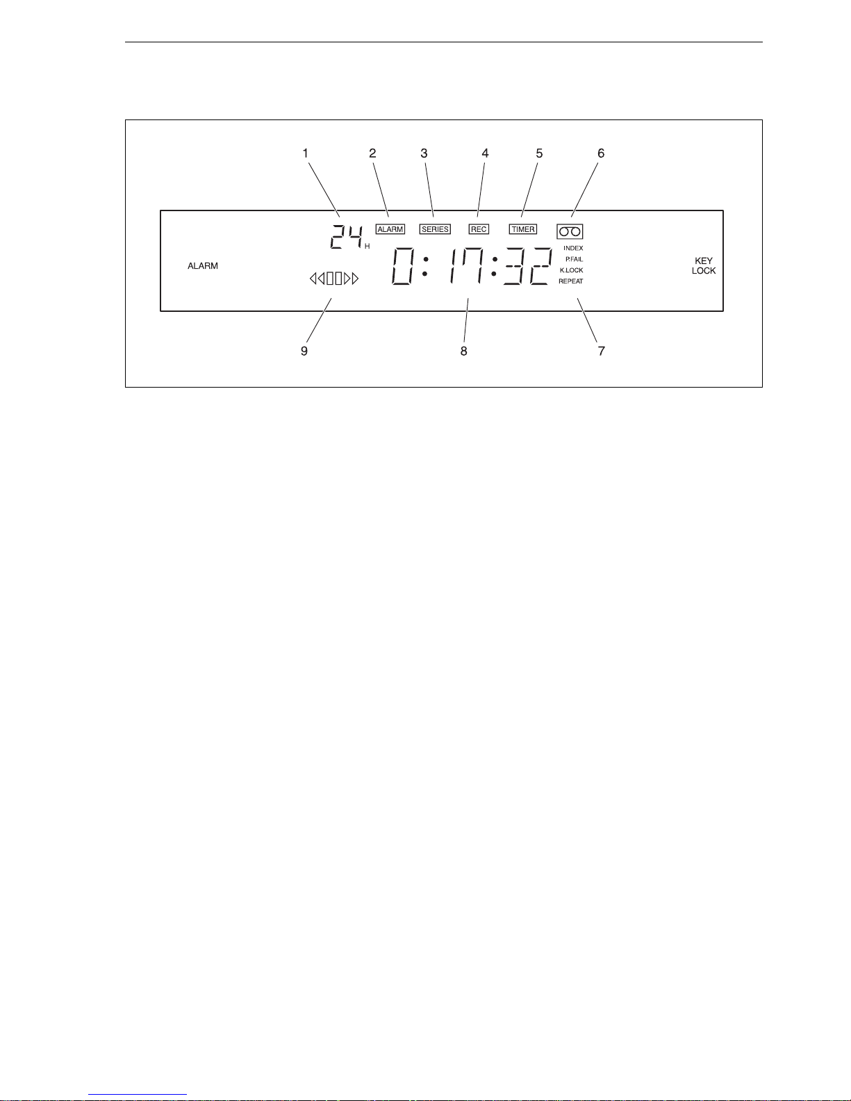
Display
Product Description
1 Tape running time
shows the tape running time currently selected:
3, 12 or 24 hours.
2 ALARM
lights up whenever the alarm-activated recording
function is running.
3 SERIES
lights up whenever various machines are
connected in cascade to provide continuous
recording.
4 REC
lights up while the unit is recording.
5 TIMER
lights up whenever the timed recording function
has been activated (by pressing the TIMER
button).
6 Cassette symbol
lights up whenever a tape is present in the
machine.
7 Status information
INDEX
flashes while the alarm index search function is
active.
P.FAIL
lights up to indicate that the unit has restarted
after a power failure during operation.
K.LOCK
lights up to indicate that the operating controls
are blocked.
REPEAT
lights up when the tape runs out, indicating
automatic rewind and re-recording.
8 Counter
displays information according to the operating
mode selected: time, tape position, total recording head operating time, error numbers,
tape counter or tape remaining.
9 Tape running mode
indicates current tape function: fast rewind,
reproduction in rewind mode, pause, normal
playback or fast forward.
Page 8
(10/2000)
8
OperationOperation
OperationOperation
Operation
On/Off
Do not plug the video recorder into the power supply
until all the required connections have been carried
out and the unit has been checked for correct
configuration and possible loose wiring.
Before operating the video recorder, ensure that the
technician responsible has installed and
programmed the unit correctly and that all functions
are in full working order.
Note
The installer will normally carry out all the
required machine programming operations
before initial start-up. Further installation
and programming instructions are provided
elsewhere in this manual (from page 18
onwards).
You may find that the video recorder
operating controls are blocked, making
them inoperable (further information on
page 28).
- If not already done, connect the video recorder to
the power supply. The unit is now in standby
mode, as indicated by the dimmed information
display (showing time, etc.)
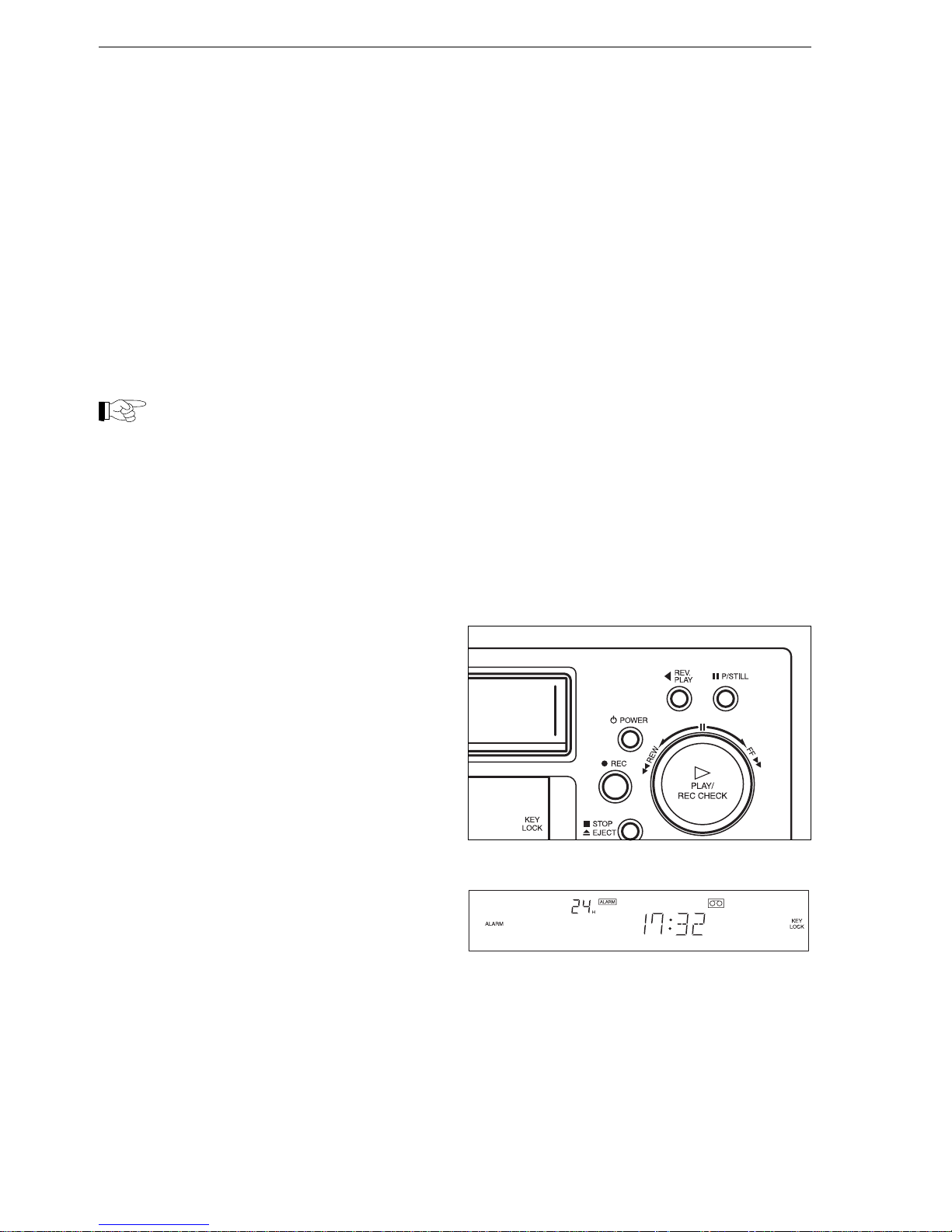
- Press the POWER button to activate the video
recorder. The information shown will now change
and the display will light up more brightly.
- Press the POWER button again to shut down the
unit.
Operation
Page 9
(10/2000)
9
Handling your videocassettes
The videotapes used in time-lapse recording units
are subjected to particularly high levels of wear and
tear. For this reason, ensure whenever possible that
you use only E-180 cassettes that have been
specifically designed for use in time-lapse video
recording systems.
Note
Do not use “High Grade” videocassettes or
those designed for entertainment use.
The use of E-240 VHS tapes specially
designed for time-lapse VCR units is
possible under exceptional circumstances,
but ensure in this case that you take proper
account of the altered running time of the
cassette.
Take care to observe all the information given on the
cassette packaging and note the following points:
- Protect the cassette from extremes of heat and
damp, and from magnetic fields.
- Keep the protective cover shut at all times and
never pull the tape out of the cassette or touch it
with your fingers.
- Keep unused cassettes in their protective cases
at all times.
- Do not tamper with the tape cassette mechanism.
Recording protection
Proceed as follows to prevent tapes being wiped
accidentally:
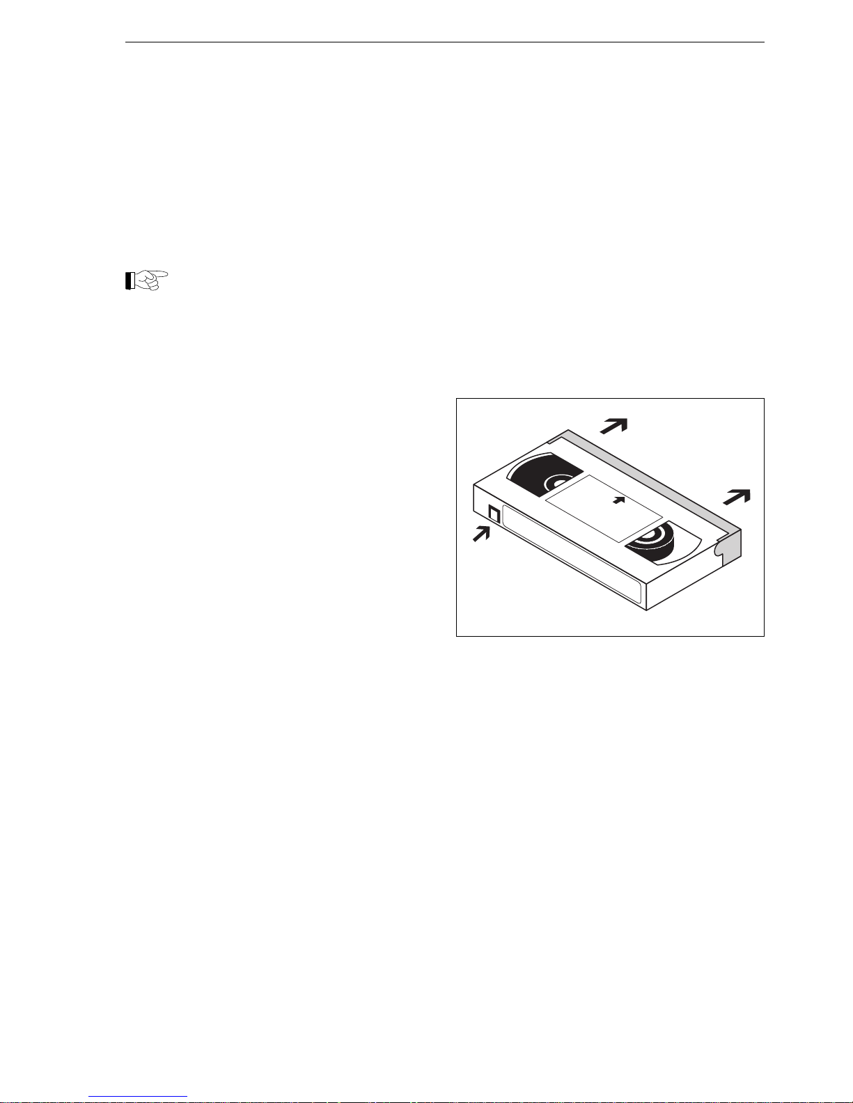
- After recording on the tape, snap off the small tab
at the back of the cassette. The tape is now available for playback only, and will be automatically
ejected from the machine whenever the REC
button is pressed.
- If you wish to re-use this tape for recording at a
later date, cover the hole left by the broken tab
with a small length of adhesive tape.
Operation
Cassette loading and removal
Videocassettes are normally marked with an arrow
on the top to indicate the direction of insertion in the
machine.
Tapes can be loaded and ejected even when the
unit is off. The video recorder switches on
automatically when a cassette is inserted.
- Load the cassette (with the transparent window
facing upwards and the tape-protection cover
towards the machine) by pushing it gently into the
tape compartment until it is taken up
automatically.
- If the VCR is running, press STOP before ejecting
the tape.
- Press the EJECT button, and the cassette will be
pushed slowly out. Carefully remove the cassette
completely.
Page 10
(10/2000)
10
Playback
Any videocassette recorded using a CBC time-lapse
VCR can be reproduced on this machine.
Note
Ensure that the selected tape recording
and playback times match one another.
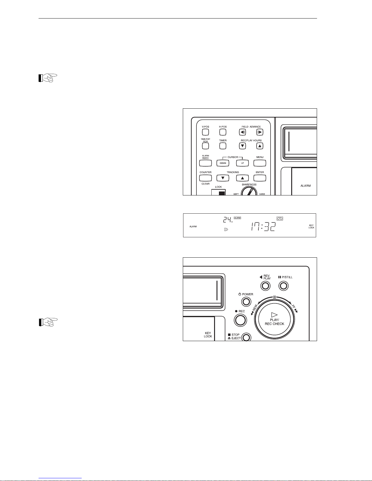
- Activate the video recorder and monitor, if not
already done.
- If not yet done, open the flap on the front of the
recorder and press the arrow keys marked REC/
PLAY HOURS to select the tape running speed
for playback. The tape running time will now
appear on the display (e.g. “24H”).
- Load a cassette and press the PLAY button to
begin playback.
- You may have to use the arrow keys marked
TRACKING to adjust the running position of the
tape and so improve the picture quality.
- Press the P/STILL button to pause the
reproduced image (freeze-frame).
- Press the FIELD ADVANCE arrow keys to
advance or rewind by one frame at a time.
- Press the STOP button to cancel the playback
function.
- Briefly turn the shuttle control anti-clockwise to
rewind the tape, or clockwise to fast-forward.
- Hold the shuttle control in position to activate the
slow rewind or tape advance functions.
- Press the REV. PLAY button to reproduce the
image in rewind mode.
Note
The freeze-frame function shuts down
automatically after five minutes to prevent
excessive wear to the recording head and
tape.
When the tape runs out, the recorder rewinds it
automatically, ejects the cassette and shuts itself
down.
Operation
Page 11
(10/2000)
11
Search functions
Visual search
You can operate the videocassette in rewind or fastforward mode - with the image displayed on-screen
- in order to help find a particular recorded scene.
- Press the PLAY button to activate the playback
function.
- Turn the shuttle control briefly and then release it.
Depending on the direction of rotation, the recorded image will now be reproduced in fast rewind or
forward mode.
- Press the PLAY button to return to normal playback.
Note
The video recorder returns automatically
from fast-search function to normal
playback mode after three minutes to
prevent excessive wear to the recording/
playback head and tape.
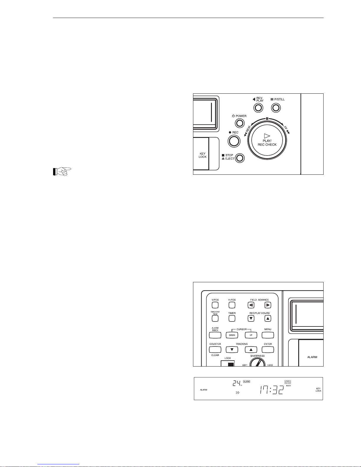
Search for alarm-activated recording (alarm index)
You can carry out a search in fast-forward or rewind
mode to find particular alarm-activated recordings.
- If the machine is running, press the STOP button
to halt the tape.
- Open the flap on the front of the unit and press
the ALARM INDEX button. INDEX will now
appear on the display.
- Turn the shuttle control briefly and then release it.
The INDEX display will now begin to flash.
Whenever an alarm-activated recording is detected,
approximately the first five seconds are reproduced
in normal playback mode. The machine then winds
on automatically to the following indexed recording.
Operation
Page 12
(10/2000)
12
Tape Counter
It is possible to display the tape counter instead of
the current time and ñ during recording or playback
ñ the amount of tape remaining.
Note
The tape counter only works when the
cassette contains recordings. It will not
register unrecorded or blank sections of
tape.
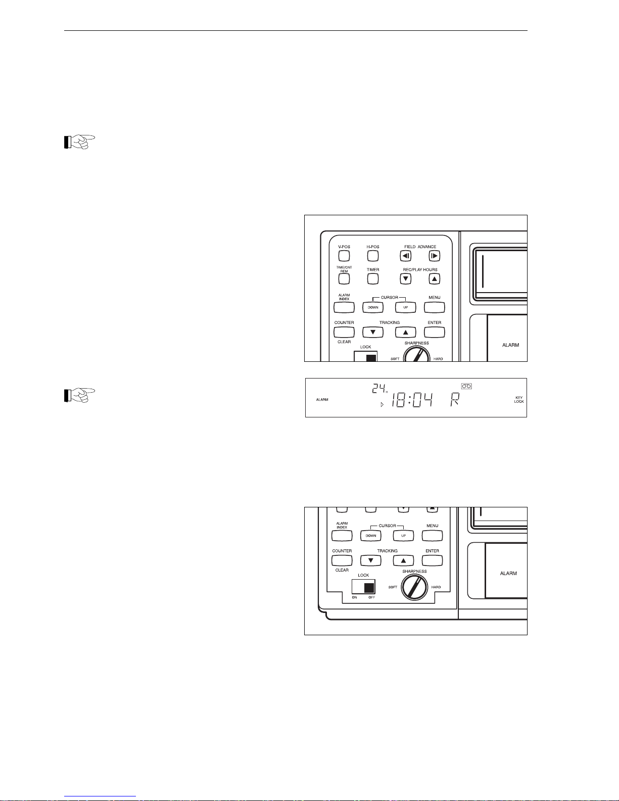
- To change from one display to another, open the
flap on the front of the recorder and press the
TIME/CNT/REM button. The display showing the
amount of remaining tape is identified by a capital
îRî.
- Briefly press the COUNTER button to reset the
counter during playback or recording.
- At the end of the current playback or recording
operation, briefly turn the shuttle control anticlockwise and then release it. The video recorder
will now rewind the tape to the point where the
counter was reset, where it will stop automatically.
Note
The display returns automatically to its
clock function whenever the cassette is
ejected or the video recorder is switched
off.
Image Sharpness
If necessary, you can adjust the level of sharpness
(contrast) while the image is being reproduced.
- Open the flap on the front of the unit and turn the
SHARPNESS control to increase or decrease the
level of contrast.
Operation
Page 13
(10/2000)
13
Recording
This VCR unit can operate in various different
recording modes:
- Manual
- Timer-activated
- Controlled by an external signal
- Alarm-activated
- Activated by other VCR units (recording in series)
- Automatic rewind and restart when tape runs out
Selection of an appropriate recording mode is
normally carried out by the user of the system, with
the recorder programmed as required or configured
to run from an external signal source. For further
information, please refer to the sections entitled
Installation (page 18 onwards) and Programming
(page 22 onwards).
Manual recording
You can start the manual recording function at any
time, provided the machine is loaded with an unprotected cassette.
Note
Recording may not begin immediately if
you set the tape running time to “00”. The
actual reaction of the video recorder
depends on how it has been programmed
(see page 25).
- Activate the video recorder and monitor, if not
already done.
- If not yet done, open the flap on the front of the
recorder and press the arrow keys marked REC/
PLAY HOURS to select the tape running speed
for recording. The tape running time will now
appear on the display (e.g. “24H”).
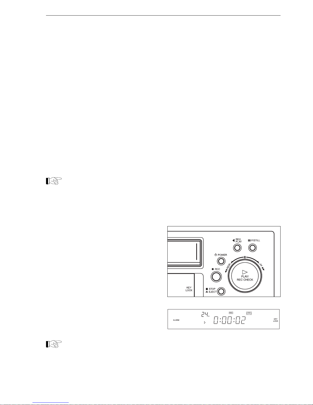
- Press the REC button. Recording will now begin,
and îRECî will appear on the display.
- Press the P/STILL button to pause the recording.
- If you wish to check for correct functioning, press
the PLAY button while recording is taking place to
display the previous few seconds of recorded
tape. The system will then return automatically to
normal recording.
- Press the STOP button to cancel the recording
function.
Note
The record-pause function shuts down
automatically and stops the tape after five
minutes to prevent excessive wear to the
recording head and tape.
Operation
Page 14
(10/2000)
14
Timer-activated recording
This unit can be programmed with up to eight
different timer-activated recording functions (see
page 26).
Note
When programming the unit for timeractivated recording, ensure that the
machine is loaded with a fully-rewound,
unprotected tape cassette.
- Activate the video recorder and monitor, if not
already done.
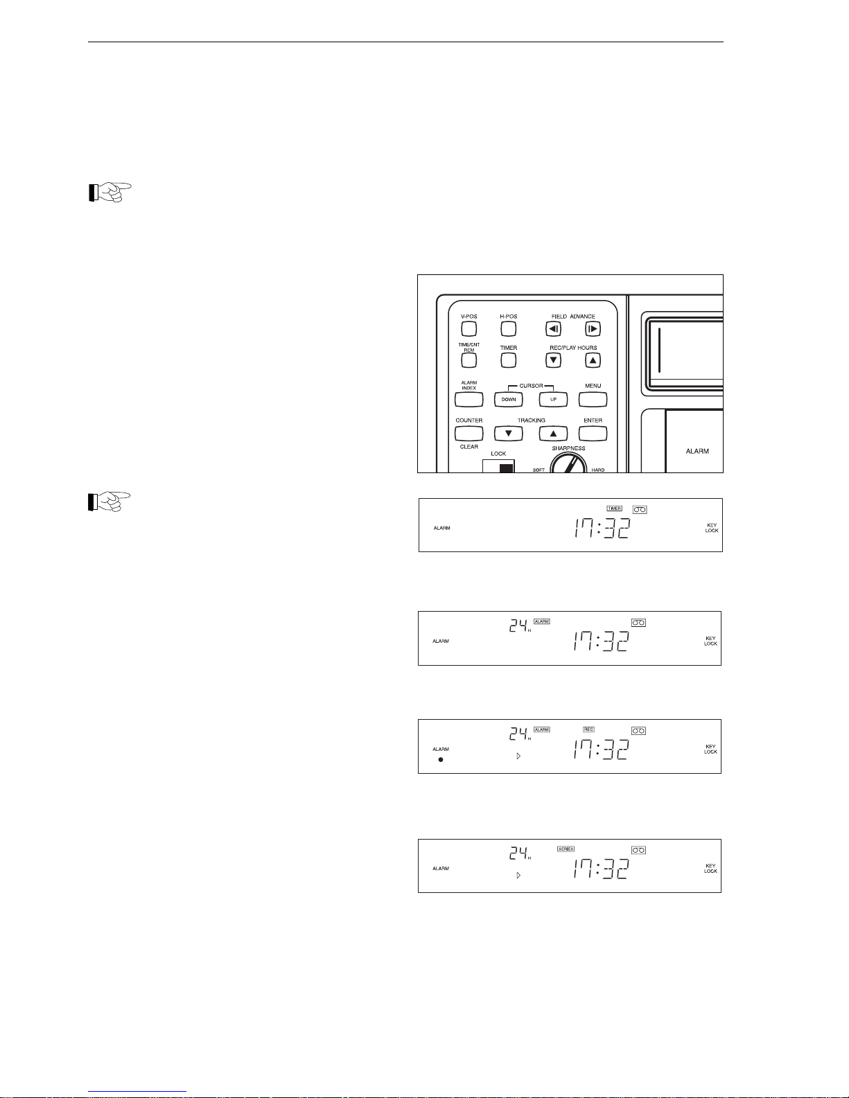
- Open the flap on the front of the unit and press
the TIMER button. The recorder will now shut
down automatically and “TIMER” will appear on
the display.
When the pre-programmed start time is reached, the
video recorder activates automatically and begins
recording. Once the end of the pre-set time is
reached, the unit stops recording and shuts down
automatically.
Note
You cannot stop the recording function
manually or switch the unit off while timeractivated recording is taking place.
Alarm-activated recording
The alarm-activated recording function is activated
by means of an external signal. Individual operating
features depend on the type of installation (see
page 20) and the programmed configuration (see
page 22 onwards).
The ALARM indication is displayed whenever the
alarm-activated recording function is programmed
as active.
The red LED indicator under the ALARM sign
flashes during an alarm-activated recording
operation, accompanied - if required - by an audible
signal tone.
Series recording
Several video recorders can be connected in sequence, with the system programmed so that each
recorder starts up automatically as soon as the tape
in the previous machine in the sequence runs out.
Individual operating features depend on the type of
installation (see page 30) and the programmed
configuration (see page 25).
The SERIES indication is displayed whenever the
series recording function is programmed as active.
Operation
Page 15
(10/2000)
15
Automatic restart function
The video recorder can be programmed to rewind
automatically as soon as the tape runs out and rerecord on the same tape.
This automatic function can be overridden, after
corresponding programming, in the event of an
alarm arising (see page 25).
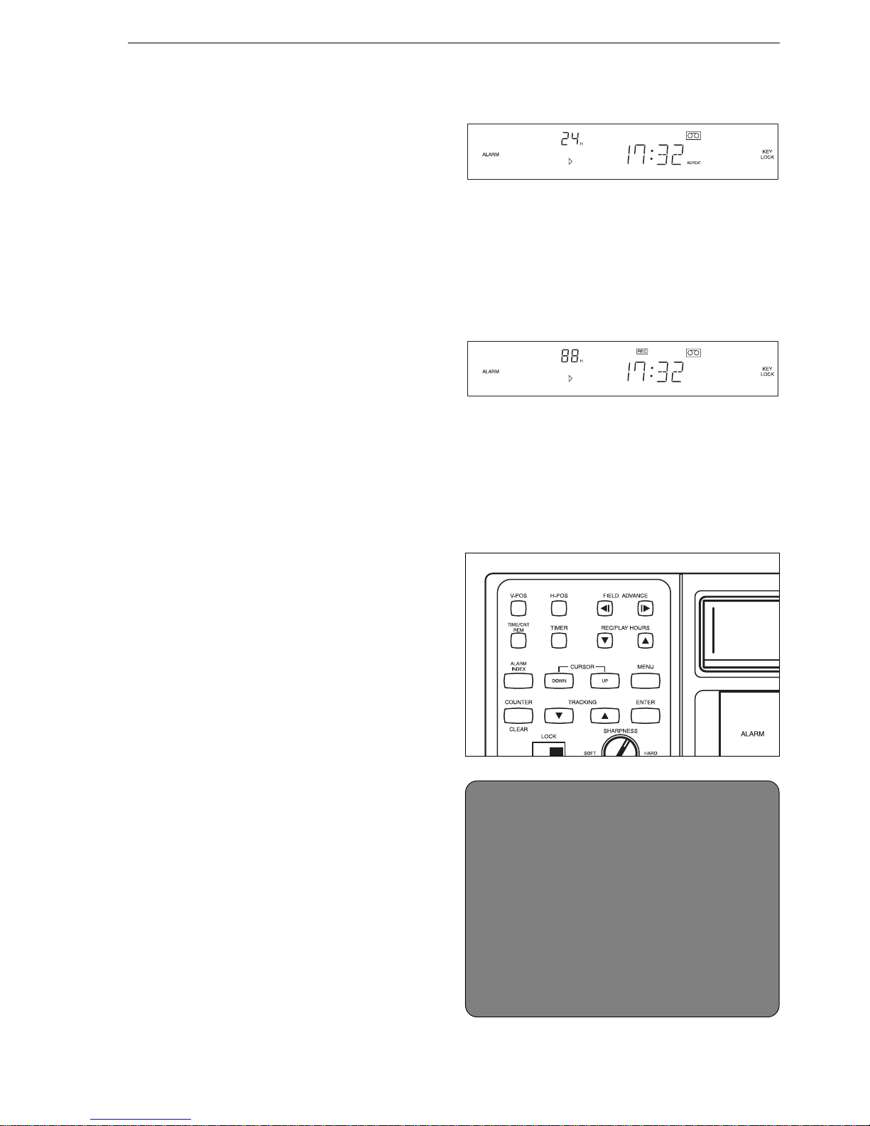
The REPEAT indication is displayed whenever the
automatic restart function is programmed as active.
Recording function activated from external signal
The video recorder can be programmed to allow
activation from an external signal source.
Note however that the recording function has to be
started manually in this case.
The REC indication appears on the display, along
with a tape running time of 00H.
Alarm recall list
This feature allows you to display a list of the last 16
alarm incidents, with the data shown in
chronological order. Once there are more than 16
incidents, the oldest item is automatically deleted.
- Stop the machine if it is still recording.
- Open the flap on the front of the unit and press
the MENU button. This will display the main
menu.
- Press the DOWN button repeatedly until ALARM
SET UP is marked, then press the ENTER button.
- Press the DOWN button repeatedly until ALARM
RECALL is marked, then press the ENTER
button. The alarm recall list will now be displayed.
- Press the DOWN button repeatedly once more if
you wish to display any further entries.
- Press the CLEAR button to delete the marked
entry.
- Finally, press the MENU button repeatedly until
the menu disappears from the display.
Operation
ALARM RECALL
1 05/11/00 18:02:42
2 04/29/00 04:32:19
3 04/29/00 03:59:56
4 --/--/-- --:--:- 5 --/--/-- --:--:- 6 --/--/-- --:--:- 7 --/--/-- --:--:- 8 --/--/-- --:--:-(DOWN) (CLEAR) (MENU)
Page 16
(10/2000)
16
Power Cuts
The video recorder detects power cuts and logs
each incident along with the corresponding date and
time, showing you when each power failure began
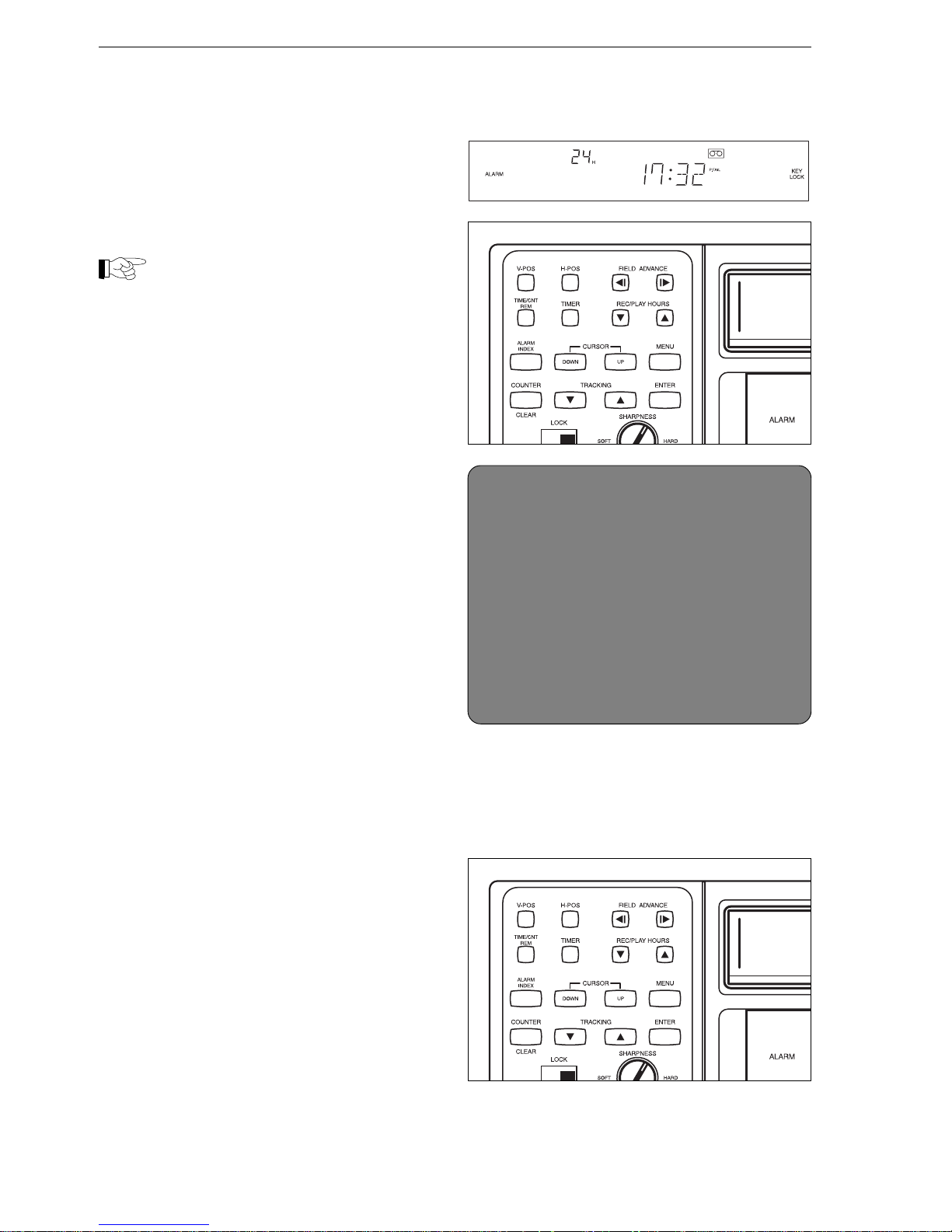
and ended. P.FAIL on the display indicates that a
power cut has occurred while the video recorder
was active.
Note
Power cuts with a duration of under one
second are not registered. Automatic
restart of the recording function is no longer
possible if the power cut in question lasts
longer than five minutes.
You can display a list of the last eight power cuts,
with the data shown in chronological order.
- Stop the machine if it is still recording.
- Open the flap on the front of the unit and press
the MENU button. This will display the main
menu.
- Press the DOWN button repeatedly until POWER
FAIL INFORM is marked, then press the ENTER
button. This will display a list of detected power
failures.
- Press the DOWN button repeatedly once more if
you wish to display any further entries.
- Press the CLEAR button to delete the marked
entry.
- Finally, press the MENU button repeatedly until
the menu disappears from the display.
Text display position adjustment
Depending on the type of programming, the monitor
will display the date, time and tape running time.
You can displace these text displays for the purpose
- for example - of making certain areas of the screen
easier to see.
- Open the flap on the front of the recorder.
- Press the V-POS and H-POS buttons repeatedly
until the texts begin to move. Position and order
the texts as required.
Operation
POWER FAIL RECALL
1 OFF 03/29/00 15:42:05
ON 03/29/00 17:32:19
2 OFF 05/10/00 23:57:05
ON 05/11/00 00:32:19
3 OFF --/--/-- --:--:- ON --/--/-- --:--:-4 OFF --/--/-- --:--:- ON --/--/-- --:--:-(UP)(DOWN)(CLEAR) (MENU)
Page 17
(10/2000)
17
Installation
InstallationInstallation
InstallationInstallation
Installation
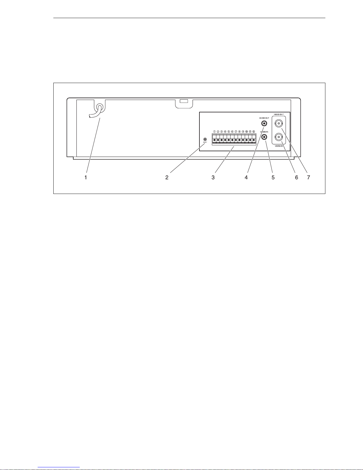
Connections on back of unit
1 Mains network power cable
for connecting the unit to the power supply
(via a suitably fused plug)
2 RESET button
for returning the video recorder to its default
settings
3 Activation in/out connection points
alarm output and input, control pulse output
and further signal inputs and outputs
4 AUDIO OUT (cinch socket)
for connecting auxiliary audio reproduction
equipment (e.g. monitor equipped with loudspeaker)
5 AUDIO IN (cinch socket)
for connection of an audio signal (e.g. from a
multiplexer)
6 VIDEO IN (BNC)
for connection of a multiplexer or camera
7 VIDEO OUT (BNC)
for connecting a monitor or additional video
recorders
Page 18
(10/2000)
18
Installation
Preparations
Caution
Ensure that you select an installation site
that will not be subject to extreme
temperatures or excessive damp. The
surrounding temperature must lie with a
range of 5 to 40 0C, with relative air
humidity less than 80 %.
Do not set the unit up in the immediate vicinity of
heaters or radiators, and avoid installation sites with
direct sunlight.
Ensure that the area around the unit is correctly
ventilated.
Install the unit on a firm and stable flat surface,
which should be of sufficient size to carry additional
items of equipment such as multiplexers und
monitors.
Connecting peripherals
Monitor
You can connect a monitor to the video recorder
directly. The monitor displays either images supplied
via the VIDEO IN socket, or reproduced recorded
images.
The monitor also displays the on-screen menus
used for configuring and programming the unit.
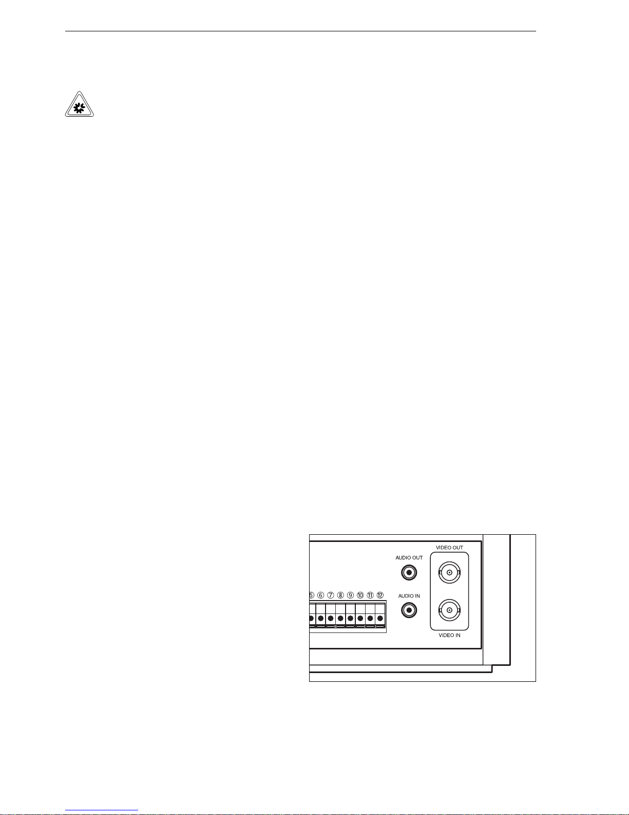
- The VIDEO OUT socket provides a link, via a
BNC cable, to the VIDEO IN socket of the
monitor.
Multiplexer or camera
You can connect a camera, a multiplexer or any
other source of video signals to the video recorder.
The recorder accepts the signals from the
corresponding video source without processing
them in any way.
- The camera or multiplexer is linked to the VIDEO
IN socket via a BNC cable.
Audio
The video recorder is fitted with both AUDIO IN and
AUDIO OUT sockets.
- The AUDIO IN socket is used to provide a link
with the audio output of the multiplexer.
- The AUDIO OUT socket is used - for example - to
provide a link with the audio input of the monitor.
Page 19
(10/2000)
19
Switching contacts
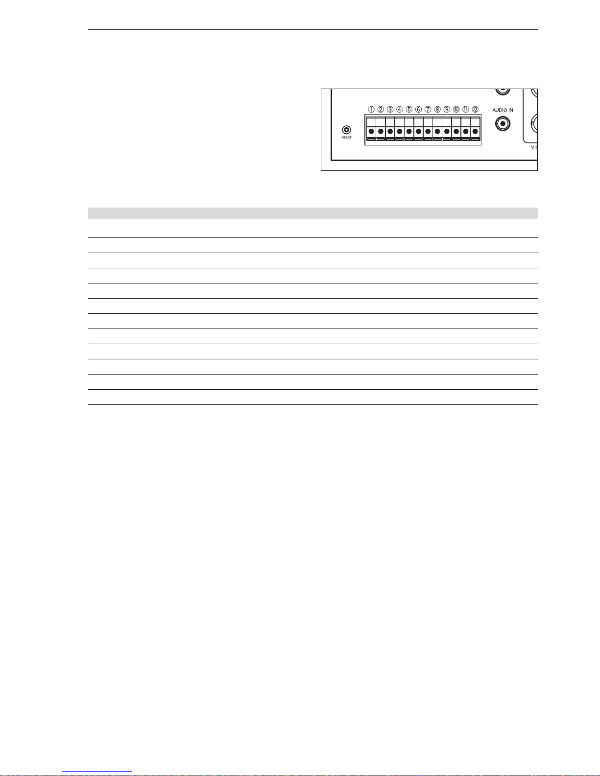
The switching contacts can be used for controlling
both the video recorder itself and a range of different
peripheral items.
The contacts are laid out as follows:
high: 4 ... 5 V, low: 0 ... 0.6 V.
The table shows the configuration of the terminal strip:
Installation
Contact Description Function Signal direction Switching duration
1 ALARM IN Alarm for starting recording IN min. 250 ms
2 ALARM OUT Alarm signal (e.g. horn) OUT duration of alarm
3 ALARM RESET Clears alarm IN min. 250 ms
4 GND Ground (earth) - 5 SERIES IN Connection in series IN min. 250 ms
6 SERIES OUT Connection in series OUT min. 250 ms
7 WARNING OUT Malfunction warning OUT until a button is pressed
8 TRIGGER OUT Multiplexer timing signal OUT min. 20 ms
9 GND Ground (earth) - 10 LOW TAPE OUT low tape warning OUT 5 min. before end of tape
11 1-SHOT REC IN Start of recording IN min. 250 ms
12 GND Ground (earth) - -
1 ALARM IN
When the video recorder is configured accordingly,
the purpose of 1 ALARM IN is to start the recording
function automatically in the event of an alarm
occurring.
2 ALARM OUT
The purpose of 2 ALARM OUT is to pass the alarm
signal on, as a horn signal, for example. This
contact remains active for the entire duration of the
alarm-activated recording operation.
3 ALARM RESET
The purpose of 3 ALARM RESET is to clear the
alarm and end the alarm-activated recording
operation. When this function activates, recording
stops and the audible alarm tone is shut off.
5/6SERIES IN/OUT
The purpose of the contacts designated 5 SERIES
IN and 6 SERIES OUT is to allow the connection in
series of various video recorders. Individual details
of these features are described in the appendix
(page 30).
Page 20
(10/2000)
20
7 WARNING OUT
The purpose of 7 WARNING OUT is to activate a
warning signal in the event of a malfunction (e.g. a
damaged tape cassette) and prevent recording.
8 TRIGGER OUT
The purpose of control pulse output 8 TRIGGER
OUT is to provide a connection to a corresponding
multiplexer input (CLOCK IN, CONTROL IN or
TRIGGER IN). This clock pulse connection is used
for synchronising the recording status of the VCR
with the video signal transfer function of the
multiplexer. This guarantees - for example - that no
images are lost if there is a brief recording function
start-up delay.
Note
Always use the control pulse output whenever possible, as the video recorder timing
signal ensures the smooth synchronisation
of the VCR and multiplexer.
10 LOW TAPE OUT
The function of 10 LOW TAPE OUT is to activate a
warning signal when the tape is running out. The
signal is activated when the tape has about five
minutes left to run.
11 1-SHOT REC IN
The purpose of 11 1-SHOT REC IN is to permit
remote activation of the single-image recording
feature (see pages 14 and 25).
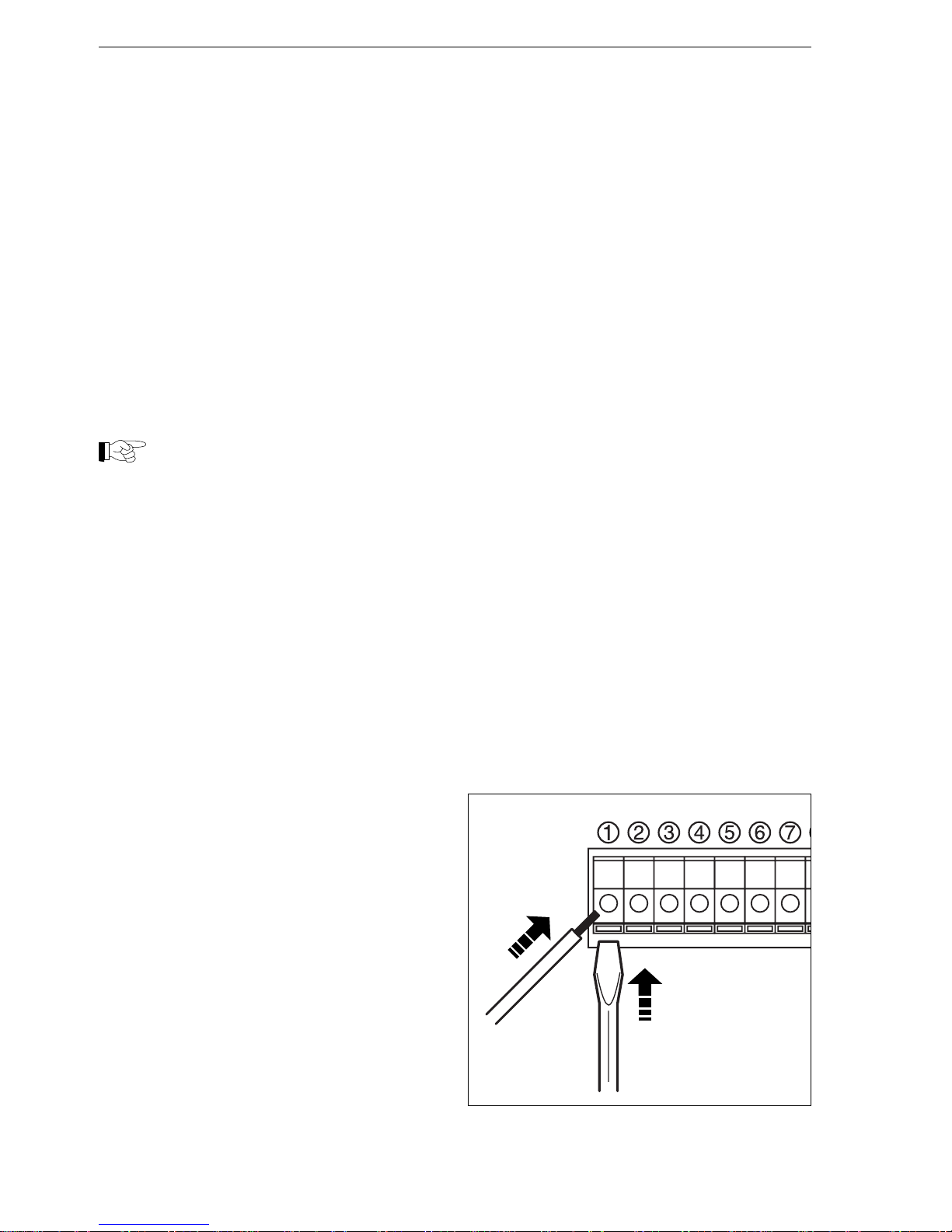
The connections are configured as screw-free plugin terminals.
- Strip about 10 mm of insulation from the end of
each connection wire.
- To release the terminal strip locking mechanism,
insert a small screwdriver as far as possible into
the slot beneath the corresponding terminal.
- Insert the bare end of the wire into the terminal
and withdraw the screwdriver.
- Carry out a final check for loose wires.
Installation
1
2
Page 21
(10/2000)
21
ProgrammingProgramming
ProgrammingProgramming
Programming
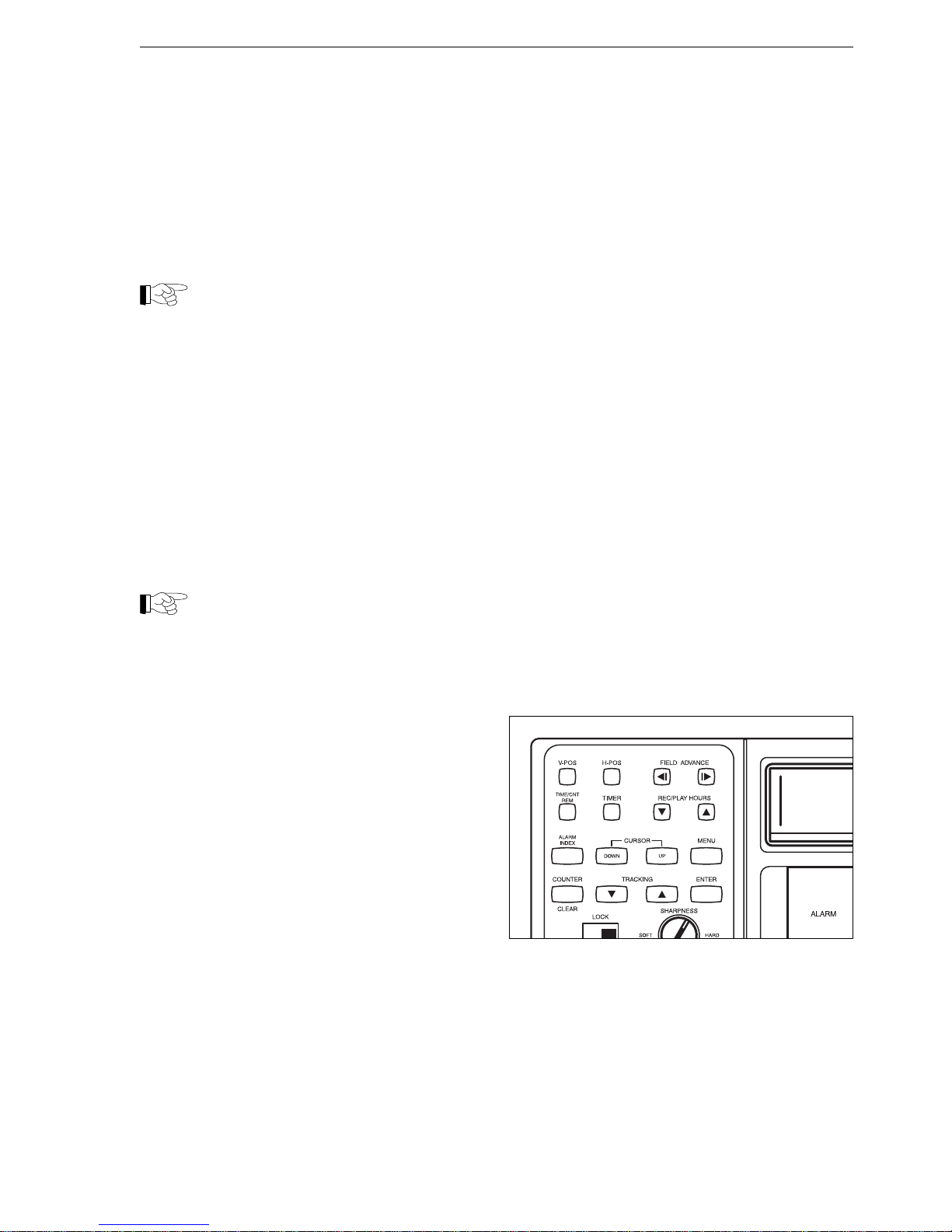
Check before starting the programming procedure
that all peripheral devices (multiplexer, monitor,
external alarm signal source) are properly
connected.
The video recorder and all ancillary equipment must
be switched on.
Note
Access to the menus is blocked when
recording is in progress (indicated by
“REC” on the display).
Basic operation
Control buttons
The various functions of the video recorder are
simple to program thanks to the on-screen menubased system. Menu entries are made using the
control buttons located behind the flap on the front
of the unit.
Note
If the menus on your particular machine
differ from those described here, it is
possible that a different version of the
software has been installed. (Please refer
to version information on the rear of the
pack).
Menu navigation is carried out using just the
following buttons:
MENU for activating the on-screen menu,
for moving up one level within the
menu, for cancelling the menu
UP/DOWN for moving from one menu item
to another
ENTER for changing to the marked menu
for altering settings
CLEAR for deleting an entry
Programming
Page 22

(10/2000)
22
Starting and ending the programming procedure
Once the unit is switched on, the camera image will
be displayed on the monitor and programming can
begin.
- Stop the machine if it is still recording.
- Press the MENU button to display the main
menu. The bottom line of each menu lists the
buttons that can be used to continue
programming.
- Finally, press the MENU button repeatedly until
the menu disappears from the display.
If no entries are made, the menus will be cancelled
automatically after a short time.
Marking and selecting
A small triangle indicates which menu item is
currently selected.
- Use the UP or DOWN buttons to change this
selection.
- Press the ENTER button to access the active
menu or select one of the available parameter
options.
- Press the MENU button again to return to the
previous menu.
Note
Work systematically through the programming procedure, carrying out all the operations corresponding to each menu before
moving on to the next.
Saving your settings
All menu configuration changes enter into effect
either immediately or as soon as the menu
disappears from the display. There is no need for a
special configuration saving procedure.
Note
The following section describes all menus
in the same order in which they are
accessed from the main menu.
Programming
M E N U
VCR SET UP
REC MODE SET UP
TIMER REC SET UP
ALARM SET UP
POWER FAIL RECALL
(UP)(DOWN)(CLEAR) (MENU)
M E N U
VCR SET UP
REC MODE SET UP
TIMER REC SET UP
ALARM SET UP
POWER FAIL RECALL
(UP)(DOWN)(CLEAR) (MENU)
Page 23

(10/2000)
23
VCR SET UP menu
This menu allows you to carry out various adjustments
to the basic VCR configuration, as described below.
VCR SET UP
CLOCK SET
ELAPSED TIME
VHS-TAPE T-120/E-180
VIDEO COLOR
DISPLAY OFF
AUDIO PLAY ON
(UP)(DOWN)(ENTER) (MENU)
CLOCK SET
The internal calendar/clock settings need to be
correct in order to permit the proper functioning of
other programmed features, such as timer-activated
recordings.
Note that the date and time formats may not
coincide with those normally used in your country.
Possible settings:
DATE Today’s date
DD Day
MM Month
YY Year
TIME Current time
HH Hours
MM Minutes
SS Seconds
ELAPSED TIME
This feature allows you to read the total operating
time of the recording/playback head (no
configuration changes possible).
DATE OF FIRST USE Date of initial start-up
PERIOD IN USE Operating time
HOURS Total hours
Programming
VHS-TAPE
Allows you enter details of the type of videocassette
you wish to use.
Possible settings:
T-120/E-180
T-160/E-240
T-180/E-260
T-210/E-300
VIDEO
This feature allows you select the video recording
quality. Select B/W if you are operating with monochrome cameras only or COLOR if you wish to
record in colour. Note that image resolution is higher
in the case of VHS-format monochrome recordings.
COLOR for colour recordings
B/W for monochrome operation
DISPLAY
This feature allows you to use the monitor to show
user information on the date, time and selected tape
running time.
Note
Disable the text display feature if the unit is
in use with a multiplexer, otherwise the
information text from the various connected
devices will overlap and obstruct a large
part of the screen area.
ON Text display feature enabled
OFF Text display feature disabled
AUDIO PLAY
Allows you to choose whether to play recordings
with or without sound.
ON Sound enabled
OFF Sound disabled
Page 24

(10/2000)
24
REC MODE SET UP menu
This menu allows you to carry out various adjustments
to recording parameters, as described below.
REC MODE
REC TIME 24H
TRIGGER OUT 1 FIELD
SERIES OFF
REPEAT OPTION:
STOP AT EOT.
(UP)(DOWN)(ENTER) (MENU)
REC TIME
This feature allows you to pre-select the tape
running time for the recording function. If you
choose the 00H setting, further adjustments can be
carried out in the new menu item designated
INTERVALL.
Possible settings:
3H 3 hours
12H 12 hours
24H 24 hours
00H Recording mode for 1-Shot REC
function
INTERVALL
With a tape running time of 00H selected, you can
define recordings carried out using the 1-SHOT
REC input terminal (see pages 14 and 21), adjusting
the time interval applied to single-image recordings.
Select the AUTO option to record an image with
each switch operation.
Possible settings:
10 SEC 1 image every 10 seconds
20 SEC 1 image every 20 seconds
30 SEC 1 image every 30 seconds
1 MIN 1 image every minute
2 MIN 1 image every 2 minutes
3 MIN 1 image every 3 minutes
AUTO 1 image for every switch operation
Programming
TRIGGER OUT
This feature allows you to split the control pulse
output signal, in order to slow
down the cycle, e.g. when using a commutator.
Note
Always select the 1 FIELD parameter when
using a multiplexer.
Possible settings:
1 FIELD
3 FIELD
5 FIELD
10 FIELD
30 FIELD
60 FIELD
SERIES
If you wish to carry out series recording with various
VCR units connected in sequence, ensure that this
parameter is set to “ON” (see page 15).
Possible settings:
ON Series recording enabled
OFF Series recording disabled
REPEAT OPTION:
This feature allows you to decide how the VCR
should react automatically when the tape runs out
during recording.
STOP AT EOT.
The recorder shuts down as soon as the tape runs
outs.
RE-REC EVEN IF ALARM
The recorder rewinds the tape and begins recording
once more, regardless of whether an alarm signal
has been received.
REWIND. STOP
The recorder rewinds the tape before shutting down.
STOP IF ALARM
The VCR rewinds the tape, but does not re-record if
an alarm signal has been received.
Page 25

(10/2000)
25
Programming
TIMER REC SET UP menu
SET DAY START END SPD
ON SAT 16:00 24:00 24H
ON SUN 00:00 24:00 24H
OFF - -:- -:- 3H
OFF - -:- -:- 3H
OFF - -:- -:- 3H
OFF - -:- -:- 3H
OFF - -:- -:- 3H
OFF - -:- -:- 3H
(UP)(DOWN)(ENTER)(CLEAR)
This feature allows you to program the unit to make
timer-activated recordings. This is done by establishing a start-up, shutdown and tape running time
for each day of the week.
You can also program in the same instructions for
every day from Monday to Friday, the weekend only
or all seven days of the week.
The system can handle up to eight different program
settings.
Note
Press the TIMER button to enable the
timer-activated recording function (see
page 15).
Possible settings:
ON Program activated
OFF Program disabled
MON Monday
TUE Tuesday
WED Wednesday
THU Thursday
FRI Friday
SAT Saturday
SUN Sunday
M-F Monday to Friday
S-S Saturday and Sunday
DLY daily
Page 26

(10/2000)
26
Programming
ALARM SET UP menu
This menu allows you to carry out various
adjustments to alarm-activated recording
parameters, as described below.
ALARM SET UP
REC MODE 3H
DURATION AUTO
BUZZER ON
ALARM READY ON
ALARM RECALL
(UP)(DOWN)(ENTER) (MENU)
REC MODE
You must select a specific tape running time for
alarm-activated recording. No recording can take
place if this option is set to OFF.
Possible settings:
OFF No recording in the event of an alarm
3H 3 hours
12H 12 hours
24H 24 hours
DURATION
This feature allows you to select the duration of the
alarm-activated recording.
Possible settings:
30 SEC 30 seconds
1 MIN 1 minute
3 MIN 3 minutes
5 MIN 5 minutes
10 MIN 10 minutes
T.END until tape runs out
AUTO for entire duration of alarm signal
BUZZER
You can choose whether you wish to activate or
disable the VCR audible alarm signal. If this feature
is enabled, the built-in speaker will emit a sound for
the entire duration of the alarm signal.
Possible settings:
OFF Alarm tone disabled
ON Alarm tone enabled
ALARM READY
You can also select the operating circumstances in
which the video recorder should react to the external
alarm signal.
Possible settings:
OFF
The VCR only reacts if a recording operation has
already started, or if the timer-activated function is
enabled.
ON
The VCR starts recording as soon as it receives any
external alarm signal, even if it is in standby mode.
Ensure that the unit is properly connected to the
mains power supply.
ALARM RECALL
This feature allows you to display a list of the last 16
alarm incidents, with the data shown in
chronological order. Once there are more than 16
incidents, the oldest item is automatically deleted
(see page 16).
POWER FAIL RECALL menu
You can display a list of the last eight power cuts,
with the data shown in chronological order. Once
there are more than 8 incidents, the oldest item is
automatically deleted (see page 17).
Page 27
(10/2000)
27
Programming
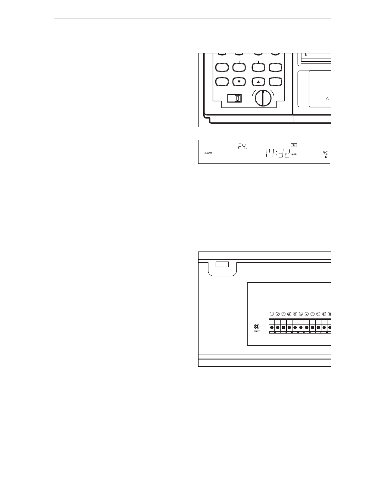
Keypad locked
You can block the VCR operating controls (and
therefore menu access) in order to prevent
accidental or unauthorised operation of the unit. The
video recorder does not respond to any control
button while this feature is active.
- Move the switch marked LOCK to its ON position.
The keypad is now blocked, “K.LOCK” appears
on the display and the LED situated beneath the
KEY LOCK sign lights up.
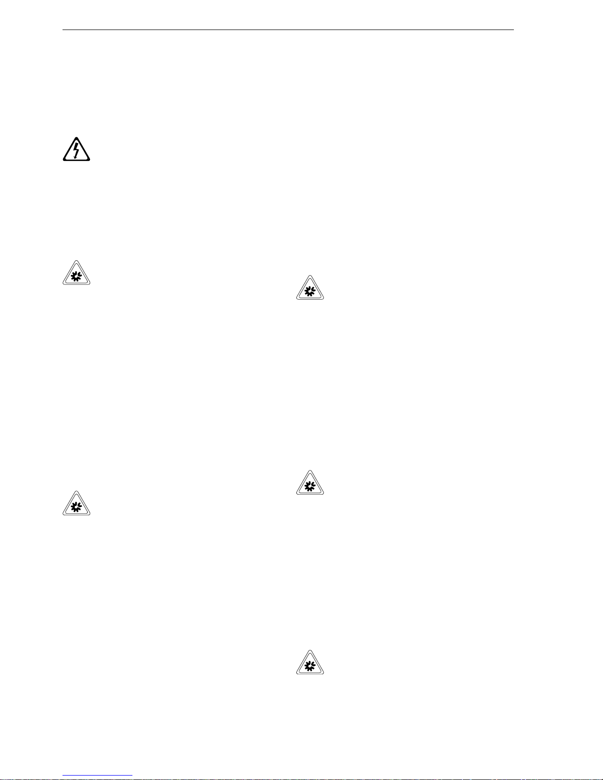
Default settings
You can return the video recorder to its default
settings if, for example, you suspect that it has been
programmed incorrectly or if the unit’s operating
circumstances have changed. The RESET button is
located on the back of the unit.
- Press the RESET button with a ball-point pen or
similar item. All user-defined program settings are
now cancelled.
- Ensure before proceeding that all menu configurations and operating parameters correspond to
your needs.
ALAR
M
ALARM
INDEX
MENU
COUNTER
ENTER
CLEAR
LOCK
SHARPNESS
ON OFF
SOFT HARD
TRACKING
CURSOR
DOWN
UP
Page 28
(10/2000)
28
Care and Maintenance
Care and maintenanceCare and maintenance
Care and maintenanceCare and maintenance
Care and maintenance
Cleaning the unit
DANGER of electric shock
Ensure that no liquid of any type is allowed
to enter the unit. The entry of liquids into
the housing can lead to fatal electric shock.
Wipe down the outside of the video recorder
regularly with a soft damp cloth, using a neutral
cleaning product to improve dirt-removing efficiency,
if required.
Caution
Do not use abrasive or corrosive cleaning
products or solvents, as they are likely to
damage the surface of the unit.
Cleaning the recording/playback head
The video recorder is fitted with a self-activating
head cleaning mechanism, which operates briefly
each time a tape is loaded into the unit.
Thorough cleaning is required after every 1,500
hours of operation, although more frequent cleaning
may be advisable under certain circumstances, such
as after the regular use of old cassettes.
Use the VCR SET UP menu to read the current total
operating hours of the recording/playback head (see
page 24).
Caution
Clean the head using a special cassette
designed for the purpose, carefully
following the instructions supplied by the
manufacturer of the head-cleaning tape. If
in doubt, please contact the CBC Technical
Service Department.
Regular inspections
This video recorder is a low-maintenance unit,
designed to provide reliable long-term operation. It
should however be subjected to a thorough inspection every10,000 operating hours to guarantee its
correct and trouble-free functioning. This inspection
includes the testing of all mechanical parts and drive
system components, with replacement as required.
All inspection work should be carried out by CBCís
Technical Service.
Please contact your nearest CBC branch or
authorised agent.
Caution
Do not attempt to carry out inspection work
yourself and do not remove or try to
replace any of the playback/recording head
or drive system components, as this can
result in serious damage to the video
recorder.
Fuse replacement
The main internal fuse is not user-accessible. All
blown fuses must be replaced by CBCís Technical
Service when rectifying the corresponding fault.
Caution
Do not attempt to carry out fuse replacement yourself. If a malfunction occurs in the
unit, it must be checked to ensure overall
operating safety.
Battery replacement
The battery is permanently soldered into the unit. If
you suspect that the battery is no longer charging
correctly (e.g. frequent clock/date resets required) it
must be replaced by CBCís Technical Service.
Caution
Do not attempt to replace the battery
yourself, as this can result in serious
damage to the video recorder.
Page 29

(10/2000)
29
Appendix
AppendixAppendix
AppendixAppendix
Appendix
Connection in series of several video
recorders
You can connect several CEC-VCR24-type video
recorders in series in order - for example - to
increase recording capacity.
This requires the interlinking of various input and
output connections of the units involved. You should
also ensure that the series recording option is
activated in the REC MODE menu (see page 25).
If the system is correctly installed and configured,
each VCR starts to record automatically as soon as
the tape in the previous unit in the sequence runs
out.
Observe the following points when configuring the
system for recording in series:
- All connected VCR units must be activated and
ready to record.
- Each VCR should be loaded with a fully-rewound
unprotected tape.
- The serial recording feature should be enabled for
each VCR unit.
The diagram shows an example of the wiring layout
for three series-connected units.
Video recorder 1 Video recorder 2 Video recorder 3
Camera
or
Multiplexer
Monitor
- Link the VIDEO IN and OUT connections of all
the VCR units involved to each other. Connect the
VIDEO IN socket of the first recorder in the sequence to the video signal source (e.g. the multiplexer) and the VIDEO OUT socket of the last
recorder in the sequence to the monitor.
- Connect together the ground (earth) points of
each terminal strip.
- Connect the SERIES OUT contact of one VCR to
the SERIES IN contact of the next recorder in the
sequence.
- Connect the SERIES OUT contact of the last
VCR in line to the SERIES IN contact of the first
recorder in the sequence.
- Connect the ALARM OUT contact with the
ALARM IN contact of the next recorder in the
sequence.
- If required, connect the TRIGGER OUT control
pulse outputs of all recorders to each other and to
the control pulse input of the multiplexer.
- If required, connect the WARNING OUT sockets
of all recorders to each other and to the external
alarm signal (e.g. horn).
Page 30
(10/2000)
30
Error codes
Certain malfunctions cause an error code to appear in the display field.
Appendix
Troubleshooting
The purpose of the following table is to help you identify the cause of malfunctions and suggest possible
remedies.
Cassette cannot be loaded
and/or is not taken up by
mechanism.
Recording function will not
start.
On-screen menus are not
displayed.
Sound reproduction correct,
but no image.
No playback picture.
Cassette is automatically
ejected at the start of a
timer- or alarm-activated
recording operation.
Flaching cassette symbol in
display field.
Faulty image reproduction.
Cassette incorrectly aligned.
Video recorder not connected to power
supply.
Video recorder fails to start up
automatically.
Keypad blocked.
There is already a cassette inside the
video recorder.
On-screen menus cannot be displayed
while unit is recording.
No recording on cassette.
Turn cassette right way round and insert once
more, ensuring that the transparent window is
facing upwards and the tape-protection cover
is pointing towards the recorder.
Remove cassette.
(by pressing STOP/EJECT button.)
Tracking incorrect.
Recording/playback head dirty or
misaligned.
Monitor is off.
Switch video recorder on manually (by
pressing POWER button.)
No cassette in machine.
Fault Possible causes Remedy
Cassette record-protected.
Faulty connction between video recorder
and monitor.
Check power supply connection, information
display should light up dimly.
Turn LOCK switch to OFF Position to unlock
keypad.
Use another tape or disable protection by
fixing adhesive tape over hole left by snappedoff tab on back of cassette.
Stop recording function.
Check connection lead.
Load cassette.
Switch monitor on.
-
Contact CBC’s Technical Service Department.
Press TRACKING button located under flap.
Try with different cassette. If fault still cannot be
remedied, contact CBC’s Technical Service
Department.
Device does not respond to
control buttons.
Error code
E2
E1
Cassette-loading error
Possible cause
Mechanical or drive system error Repeat affected procedure, if fault still
cannot be remedied, contact CBC’s
Technical Service Department.
Remedy
Remove cassette and insert once more.
E3
E4
E5
Page 31

(10/2000)
31
Appendix
Resale, disposal
If you sell or otherwise transfer ownership of the
video recorder, be sure to hand it over along with
these installation and operating instructions.
The video recorder contains environmentally
harmful substances, so ensure that eventual
disposal or scrapping is carried out according to the
corresponding rules and legislation in this area.
Have defective or unserviceable units and components disposed of by a specialist waste-collection
organisation, or ensure that they are consigned to
your local special refuse facility.
Technical specifications
Supply voltage 100 - 240 VAC, 50/60 Hz
Power consumption 13 W (approx.)
Fuse rating 250 V T, 1.6 A
Video system VHS NTSC
Video input 1 X BNC, VBS 1.0 Vp-p 75 Ohm
Video output 1 X BNC, VBS 1.0 Vp-p 75 Ohm
Recording system 4 heads, azimuth helical scan device
Rewind time approx. 60 sec. (E-180 tape)
Signal-to-noise ratio > 43 dB
Audio input 1 X Cinch, -7.8 dB, >47 kOhm
Audio output 1 X Cinch, -7.8 dB, <1.5 kOhm
Audio frequency range 200 Hz ... 10 kHz
Operating conditions Temperature: 5 - 40 0C
rel. air humidity: 80%, non-condensing
Storage conditions Temperature: 0 - 50 0C
If you intend to store the unit for longer than one month,
add fresh desiccant and protect the device from moisture
by packing it in a sealed container.
Dimensions (W X H X D) 360 X 94 X 270 mm
Weight 3.8 kg (approx.)
Page 32

 Loading...