

Ganz CEC-WP-NV49AB, CEC-WP-E38, CEC-WP-E60, CEC-WP-EV48, CEC-WP-EV48A Instruction Manual
...Page 1

NTSC VERSION
PAL VERSION
CEC-WP-NV49AB
CEC-WP-E38
CEC-WP-E60
CEC-WP-EV48
CEC-WP-EV48A
CEC-WP-PV49AB
CCIR VERSIONEIA VERSION
CEC-WP-C38
CEC-WP-C60
CEC-WP-CV48
CEC-WP-CV48A
1
Page 2

Thank you for your purchase of this product. Before operating the product, please read this
instruction manual carefully to ensure proper use of the product. Please store this instruction
manual in a safe place for future reference.
CONTENTS
FEATURES --------------------------------------------------------------------------------------------- P.2
CAUTIONS --------------------------------------------------------------------------------------------- P.2
PART NAMES ------------------------------------------------------------------------------------------ P.4
INSTALLATION ---------------------------------------------------------------------------------------- P.4
SPECIFICATION ------------------------------------------------------------------------------------ P.7&8
FEATURES
- Stylish Design for External Home Surveillance
- Water & Fog Resistant Glass Coating
- Integrated 4-9mm Auto Iris Varifocal Lens (CEC-WP-NV49AB/PV49AB)
- Integrated 4-8mm Auto Iris Varifocal Lens (CEC-WP-EV48/EV48A/CV48/CV48A)
- IP67 Environmental Rating
- 12VDC Power Input
This symbol indicates that there is a possibility of injury or damage to equipment.
1. Power supply
(1) Use only with a 12V DC power supply marked class 2.
(2) Be sure to connect each lead to the appropriate terminal. Wrong connection may cause
malfunction and/or damage to the video camera.
2
Page 3

2. Operating and storage locations
(1) Do not attempt to aim the camera at the sun or other extremely bright objects that cause
smear to appear irrespective of whether the camera is operating or not. This can damage the
CCD (Charge Coupled Device).
(2) Do not place the camera in the following locations.
⁄ Locations subjected to extremely high or low temperature
¤ Locations under water.
‹ Locations subjected to excessive vibrations.
(3) When this camera is installed near the equipment, like a wireless communication device
that emits strong electromagnetic field, some irregularity such as noise on monitor screen
may happen.
3. Handling of the unit
Do not allow the camera to be subjected to strong impacts or shocks. The camera could be
damaged by improper handling or storage.
- Never attempt to disassemble or modify the camera.
- If any abnormality should occur, immediately turn off the power and consult your dealer.
This equipment has been tested and found to comply with the limits for a Class A digital device,
pursuant to Part 15 of FCC Rules. These limits are designed to provide reasonable protection
against harmful interference when the equipment is operated in a commercial environment. This
machine generates, uses, and can radiate radio frequency energy and if not installed and used in
accordance with the instruction manual, may cause harmful interference to radio communications.
Operation of this equipment in a residential area is likely to cause interference, in which case the
user will be required to correct the interference at the userís own expense.
The CE Marking is a Directive Conformity mark of the European Union (EU).
3
Page 4

PART NAMES
Top
Front
‹
¤⁄
‡
›
fi
°
Bottom
fl
Rear
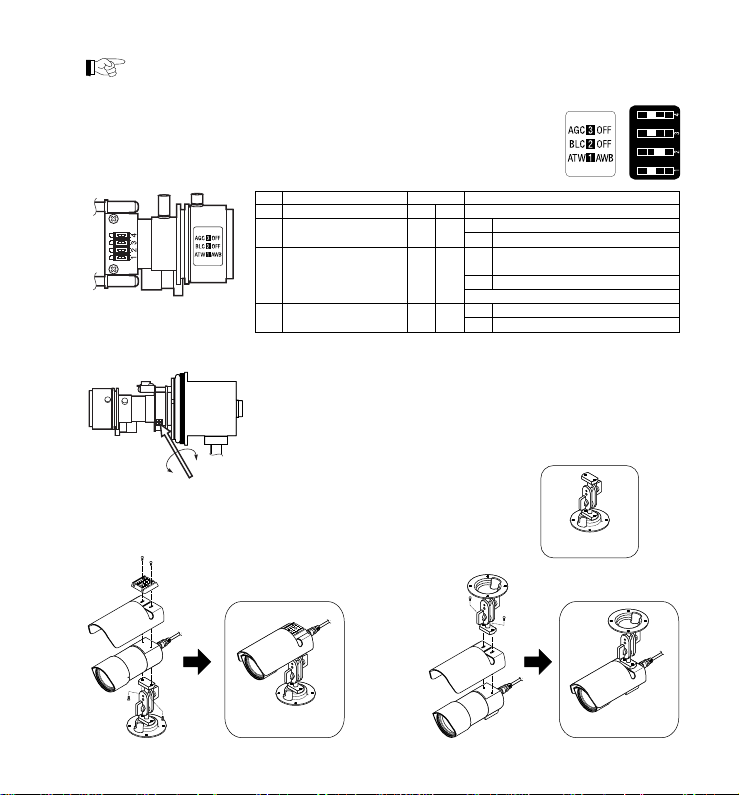
INSTALLATION
⁄ FOCUS & ZOOM ADJUSTMENT
⁄ 6-pin cable connector (female)
¤ 6-pin cable connector (male)
‹ Base mount
› Front housing
fi Rear housing
fl Upper arrow
‡ Sunshield
° Bracket
W
T
N
∞
CEC-WP-E38/E60/C38/C60
CEC-WP-EV48/EV48A/CV48/CV48A
CEC-WP-NV49AB/PV49AB
1. Remove the front housing of the camera
2. Loosen the lock screw
3. Adjust the zoom by turning the pin to either T
or
W.
After adjusting the zoom turn the focus pin for clear picture.
4. Fasten the lock screw when the focus is adjusted.
4
Page 5
Be sure to detach the front housing in a dry environment to avoid risk of moisture
invasion.When reattaching the front housing, make sure to tight the front
housing formly to assurewater resistance.
¤ DIP SWITCH SETTING
‹ DC IRIS LEVEL ADJUSTMENT
for CEC-WP-NV49AB/PV49AB
No. Name Position Function
4 No Function — — —
3 Auto Gain Control AGC OFF
2 Back Light Compensation BLC OFF
*BLC function is effective with AGC function
1 Auto White Balance ATW AWB
for CEC-WP-NV49AB/PV49AB
1. Turn the dip switch AGC to OFF.
2. Adjust DC iris level according to lightcondition.
3. Turn the dip switch AGC to ON.
› MOUNTING BRACKET AND SUNSHEILD
Tight the screw to attach the sunshield and the bracket.
Please refer to the drawing on the right.
Wall Mount Ceiling Mount
5
(Factory Settings)
AGC Gain level varies from 0-26dB
OFF Gain level fixes at 0dB
Set to this position when strong light
BLC
comes from behind the target
OFF Normal position
ATWTraces and adjusts WB automatically
AWB Adjusts WB automatically and fixes it
Bracket
Page 6
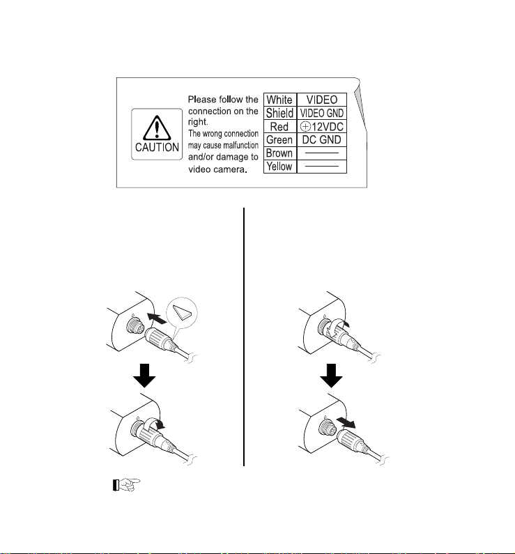
CONNECTION OF WEATHER PROOF CABLE
Push to lock
Make sure to point the arrow to the
top with the camera arrow for proper
connection.When connecting keep
pushing the plastic part to the end for
lock.
The cable connection must be attached
in all the way to assure water resistance.
Slide release to unlock
When disconnecting pull out the
lock-releaf by hand for unlock. please
do not grab the plastic part of cable
to pull.
6
Page 7
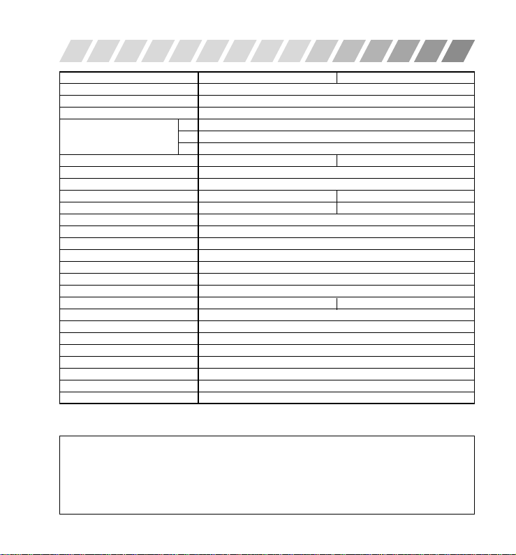
SPECIFICATION
Model No. CEC-WP-NV49AB CEC-WP-PV49AB
Focal Length 4.0 - 9.0mm
Max. Aperture Ratio 1 : 1.6
Iris F1.6 - 360
Angle Of View H 51.8 - 23.8
TV System NTSC PAL
Scanning System 2:1 Interlace
Image Sensor 1/4" IT. CCD
Effective Elements (H x V) 768 x 494 752 x 582
Scanning Frequency (H / V) 15.734kHz / 59.94Hz 15.625kHz / 50.0Hz
Video Outputs 1.0V (p-p) / 75 Ω
Resolution (H) 480 TV lines
Min. Illuminance (50IRE) 2.5 Lux
AGC Less Than 26dB
S/N Ratio (AGC Off) More Than 48dB
Gamma Characteristics 0.6
Sync. System Internal
Iris Control DC Iris : 1/60 Sec. Fixed DC Iris : 1/50 Sec. Fixed
White Balance ATW / AWB
Power Supply DC12V ± 10%
Power Consumption (Max.) 180 mA
Ambient Temperature Operation : –30°C ~ +50°C
External Dimensions 135mm (L) x 56mm (ø)
Weight Approx. 360g
Dip Switch Setting AGC / BLC / WB
Input & Output 6 Pins Weather Proof Connector
Features and specifications are subjected to change without any notice for further improvement.
NOTE
D 66.1 - 29.7
V 38.3 - 17.8
7
Page 8

Model No. CEC-WP-E38 / E60 / EV48 / EV48A CEC-WP-C38 / C60 / CV48 / CV48A
Focal Length 3.8mm / 6.0mm / 4.0-8.0mm / 4.0-8.0mm
Max. Aperture Ratio 1:2.0 / 1:2.5 / 1:2.0 / 1:2.0
Iris F2.0 / F2.5 / F2.0-2.8 / F2.0-300
D 90.0 / 57.8 / 89.2-44.2 / 89.2-44.2
Angle Of View H 71.5 / 45.7 / 70.1-35.3 / 70.1-35.3
V 53.4 / 34.0 / 51.6-26.5 / 51.6-21.5
TV System EIA CCIR
Scanning System 2:1 Interlace
Image Sensor 1/3" IT. CCD
Effective Elements (H x V) 512 x 492 512 x 582
Scanning Frequency (H / V) 15.734kHz / 59.94Hz 15.625kHz / 50.0Hz
Video Outputs 1.0V (p-p) / 75 Ω
Resolution (H) 380 TV lines
Min. Illuminance (50IRE) 0.6 Lux / 0.8 Lux / 0.6 Lux / 0.6 Lux
AGC (Max.) +12dB
S/N Ratio (AGC Off) More Than 47dB
Gamma Characteristics 0.45
Sync. System Internal
Iris Control
White Balance ATW / AWB
Power Supply DC12V ± 10%
Power Consumption (Max.) 140mA / 140mA / 140mA / 180 mA
Ambient Temperature Operation : –30°C ~ +50°C
External Dimensions 135mm (L) x 56mm (ø)
Weight Approx.330g / 330g / 330g / 360g
Input & Output 6 Pins Weather Proof Connector
Features and specifications are subjected to change without any notice for further improvement.
AES : 1/60 ~ 1/80,000 Sec. AES : 1/50 ~ 1/80,000 Sec.
DC Iris : 1/60 Sec. Fixed DC Iris : 1/50 Sec. Fixed
PRINTED IN JAPAN
009-1.0
8
 Loading...