

Page 1

CBC (EUROPE) LIMITED
Digital RECORDER
CDR-16T
(1ST EDITION)
OPERATION MANUAL
Page 2

General Considerations
Power Supply
Verify your unit has the correct voltage specifications for your power source prior to applying
power by reading the voltage range on the rear panel near the AC connector. The CDR-16T
normally operates on 100-240VAC ±10%; 50/60Hz. Do not attempt to operate these units using
a source having different specifications.
Location
Avoid using the CDR-16T in areas having high humidity, high temperature, or excessive dust.
Adequate ventilation is also required for optimum performance. As a result of this consideration,
ensure no other equipment is located or installed closer than 5cm to any unit.
Fuse
If a fuse blows, replace it with one the same rating as indicated below with unit power switched
off. Note only qualified personnel should perform fuse replacement. If fuse blows frequently, turn
power off and contact your supplier.
Fuse used in CDR-16T is as below:
250V, T4.0A, slow blow type (100-240 VAC)
Desk or Tabletop Use
Unit baseplates are fitted at the factory with rubber feet to allow immediate usage as a desk or
tabletop unit.
Rack Mounting
The CDR-16T can be mounted to EIA standard rack units. When rack mounting a unit, remove
the rubber feet and use the accessory rack mount brackets (rack ears).
Page 3

Upon Receipt
Unpacking
The CDR-16T is fully inspected and adjusted prior to shipment and can be operated immediately
upon completing all required connections and operational settings.
Check your received items against the packing list below.
ITEM
QTY
REMARKS
CDR-16T 1
36GB, 72GB or 180GB internal hard drive model
depending on purchase
SCSI Termination
Connector
1
For connection to SCSI connector if no external
drives connected. (Or to last SCSI connector of
last drive if external drives configured.)
AC Cord 1
Rack Mount Brackets 1 pr. EIA standard type
Operation Manual 1
Check
Check to ensure no damage has occurred during shipment. If damage has occurred, or items
are missing, inform your supplier immediately.
Page 4

TABLE OF CONTENTS
1. Prior to Starting ....................................................................................................................1
1-1. Welcome........................................................................................................................1
1-2. About the CDR-16T......................................................................................................1
1-3. About This Manual ........................................................................................................2
2. Panel Descriptions...............................................................................................................3
2-1. Front Panel....................................................................................................................3
2-2. Rear Panel.....................................................................................................................6
3. Setup and Connection .........................................................................................................8
3-1. Connection .....................................................................................................................8
3-1-1. Basic Connection..................................................................................................8
3-1-2. Computer / Remote Control Connection...........................................................9
3-1-3. External Hard Drive Setup.................................................................................10
3-2. Connector Information...............................................................................................11
3-2-1. RS-232C Connector............................................................................................11
3-2-2. Remote Connector..............................................................................................12
3-2-3. Alarm Connector..................................................................................................14
3-2-4. SCSI Connector...................................................................................................16
4. Basic Operation..................................................................................................................17
4-1. Power ON / OFF.........................................................................................................17
4-2. Resetting to Factory Defaults...................................................................................18
4-3. Screen Display ............................................................................................................18
4-3-1. Full Screen...........................................................................................................18
4-3-2. Split Screen ..........................................................................................................22
4-3-3. Date / Time Messages........................................................................................23
4-4. Full Screen Display Operations................................................................................24
4-4-1. Zoom.....................................................................................................................25
4-4-2. Auto Sequence....................................................................................................26
4-5. Split Screen Display Operations ..............................................................................27
4-5-1. Patterns.................................................................................................................28
4-5-2. Channel Groups..................................................................................................29
4-5-3. Changing Main Position Camera......................................................................31
4-5-4. Channel Group Auto Sequence........................................................................33
4-6. Record / Playback......................................................................................................36
Page 5

4-6-1. Manual Record....................................................................................................36
4-6-2. Auto Record.........................................................................................................36
4-6-3. Playback and Search..........................................................................................37
5. Using Menus.......................................................................................................................38
5-1. Accessing MAIN Menu..............................................................................................38
5-2. Accessing Function Menus.......................................................................................41
6. MAIN Menu Settings.........................................................................................................42
6-1. Protect..........................................................................................................................44
6-2. Split Position ................................................................................................................46
6-3. Record Programming.................................................................................................48
6-3-1. Continuous Record.............................................................................................49
6-3-2. Pre Alarm Record................................................................................................52
6-3-3. One Shot Record.................................................................................................54
6-3-4. Regarding Record Channel Setting .................................................................55
6-3-5. Regarding Timelapse / Update Mode Setting .................................................58
6-3-6. Regarding Trigger Setting..................................................................................62
6-3-7. Regarding Continuous Record Setting............................................................63
6-4. Timer Program............................................................................................................66
6-5. Auto Seq Time.............................................................................................................69
6-6. Title Settings................................................................................................................70
6-7. Date / Time Settings...................................................................................................71
6-8. Display Mode...............................................................................................................72
6-9. Alarms..........................................................................................................................76
6-9-1. Alarm Settings......................................................................................................76
6-9-2. Regarding Alarm Display...................................................................................78
6-10. HDD............................................................................................................................80
6-10-1. Assign HDD Use...............................................................................................81
6-10-2. Format HDD.......................................................................................................83
6-10-3. Clear Event........................................................................................................85
6-11. Other Settings...........................................................................................................87
6-12. System Information..................................................................................................88
7. Function Menu Settings....................................................................................................89
7-1. Date / Time Search.....................................................................................................91
7-2. Index List Search ........................................................................................................93
7-3. HDD Information .........................................................................................................96
7-3-1. All Connected HDD.............................................................................................96
Page 6

7-3-2. Specified HDD.....................................................................................................98
7-4 Power ON / OFF Log..................................................................................................99
8. Sensor Operation............................................................................................................101
8-1. Sensor Menu............................................................................................................101
8-1-2. Sensitivity Settings...........................................................................................102
9. DVD Option......................................................................................................................105
9-1. DVD Option Information.........................................................................................105
9-2. DVD Menu screen...................................................................................................106
9-2-1. Assigning DVD Use.........................................................................................107
9-3. Formatting DVD.......................................................................................................109
9-4. Clearing Events.........................................................................................................111
9-5. User Select Backup..................................................................................................112
9-5-1. To Make User Backup ......................................................................................114
9-5-2. Changing Disks During User Backup.............................................................117
9-6. Auto Backup..............................................................................................................118
9-6-1. Auto Backup ON/OFF.......................................................................................118
9-6-2. Auto Backup / Program Relationship.............................................................119
9-6-3. Changing Auto Backup Disk...........................................................................121
9-6-4. Auto-backup Memory Function......................................................................123
9-6-5. Auto Backup Interrupt......................................................................................125
9-7. Timer Auto Backup..................................................................................................126
9-7-1. Auto Backup Using Timer Program...............................................................126
9-7-2. Regarding Timer Auto Backup.......................................................................127
9-7-3. Changing Disk During Timer Auto Backup...................................................128
9-7-4. Record During Timer Auto Backup................................................................129
9-8. Viewing Backup Data..............................................................................................130
9-9. DVD Index Search...................................................................................................131
9-10. DVD Drive Information ..........................................................................................133
9-11. Other Settings........................................................................................................134
10. If Problems Occur ......................................................................................................... 135
11. Specifications & Dimensions.......................................................................................137
11-1. Unit Specifications.................................................................................................137
10-2. External Dimensions.............................................................................................139
Page 7

1
1. Prior to Starting
1-1. Welcome
Congratulations! By purchasing a CDR-16T you have entered the world of CBC and its many
innovative products. Thank you for your patronage and we hope you will turn to CBC products
again and again to satisfy your video and audio production needs. Whatever your needs, talk to
your CBC representative. We will do our best to be of continuing service to you.
1-2. About the CDR-16T
The CDR-16T combines the best features of digital recorders and multiplexer products in one
compact package. Triplex operation capability, high quality performance and fast response
make it excellent for use at banks, casinos, stores, factories, theaters, museums, governmental
institutes, airports or other institutions with ongoing surveillance / observation needs. Units are
available shipped with one of three different capacity internal hard drives; (36GB), (72GB) or
(180GB).
Up to 16 composite video camera signals can be input and frame-switch recorded into its hard
disk drive memory. It also has a built-in frame synchronizer with 2-frame wide window correction
to assure even asynchronous signals can be fully utilized. Each recorded camera scene can be
retrieved and displayed independently (full screen), or multiple camera channels can be viewed
simultaneously on the same monitor as a split display. Motion adaptive JPEG compression
record, selectable compression rates (record quality settings), alarm record real time (NTSC 60,
PAL 50 fields / sec.) and multiple record mode settings.
All alarm events, including power ON/OFF, can be time stamped with year, month, date, hour,
minute and second of occurrence. Each event recorded can also be nonlinearly accessed at any
time for review and observation. Picture quality remains high from first playback to last; no
deterioration occurs no matter how many times the same scene is replayed. There is also no
picture disturbance during shuttle operation and slow motion playback is extremely smooth.
Features
Ø No PC based technology. Operate as stand alone. Designed to insure long term reliability.
Ø Accepts any asynchronous or synchronous composite color or B/W signal input.
(Loopthrough output of each input is possible.)
Ø Input video recorded to internal hard disk drive.
Ø Optional DVD drive to back up critically needed security recordings.
Ø Nonlinear recording means nearly instantaneous access to needed video.
Ø Configure multiple external hard drives to increase record capacity.
Ø Specify drives as ‘playback only’ or ‘record / playback’ use.
Ø Noise free motion during shuttle, noise free stills during jog.
Ø Smooth slow motion playback, no picture deterioration after repeated playbacks.
Ø 3000 alarm index memory for each configured HDD. Year, month, day, hour, minute, and
second of occurrence memorized for each alarm.
(Continued following page.)
Page 8

2
Ø Record realtime or using one of the record interval (update or timelapse) settings.
Ø Full screen and split display auto camera switchover (dwell time) selectable as 1-30 seconds.
Ø Triplex operation capable; recorded signals can be retrieved and viewed, or camera inputs
directly observed full size or split display mode, on a single monitor while still recording.
Ø Built-in character generator allows title ID line of up to 16 alphanumeric characters to be
displayed for each camera input depending on display mode.
Ø RS-232C interface for computer command control of most operational functions.
1-3. About This Manual
This manual is intended to help the user easily operate the CDR-16T and make full use of its
functions during operations. Before connecting or operating your unit, read this operation
manual thoroughly to ensure you understand the product. After reading, it is important to keep
this manual in a safe place and available for reference.
Page 9

3
2. Panel Descriptions
2-1. Front Panel
Where:
① Power Switch
Switch used to turn unit power ON / OFF. Power is ON when power indicator ② is lit green.
② Indicators
POWER indicator lights green whenever power switch is set to ON and power is applied to the
unit.
DRIVE 1 indicator lights green whenever drive 1 (hard disk) is accessed.
DRIVE 2 indicator lights green whenever drive 2 (optional DVD) is accessed.
FAN ALM indicator lights red whenever rear panel fan fails. (If this happens, turn off your unit
immediately and contact your nearest CBC representative.)
③ AUTO / ALARM RESET
AUTO (button lit)
U sed to initiate auto sequence switching (full or split screen ) of camera channels when in LIVE
mode. (See sec. ‘4-4-2. Auto Sequence’ and ‘ 4-5-4. Channel Group Auto Sequence’.)
ALARM RESET (button flashing)
Button goes to flashing w hen an alarm signal is input or a video signal is lost. Pushing this button
at that time (alarm condition) usually resets the unit to normal operation. (Current alarm
terminated, awaiting next alarm input.)
Alarm cannot be reset, however, if alarm signal input is still low level condition and setting in
related alarm menu is to LEVEL. (See sec. ‘ 6-9-1. Alarm Settings’.)
(Continued following page.)
CD R-16T D igital R ecorder
FWDREV
CD R-16T
D igital R ecorder
FWDREV
CD R-16T
D igital R ecorder
FWDREV
CD R-16T
D igital R ecorder
FWDREV
P O W ER
ZO O MCH ST O P JO G /S HT L
C O N TR O L
P LAY* LV/P B
M E NU
M O N I TO R
S PLIT
RES ET
ALAR M
B C DA
C AM E R A SE LE C T
2 3 4 5 6 7 8A UT O 1 9 10 11 12 13 151 4 16
EN TE R
D R IVE 1
F AN AL M
D R IVE 2
FE
FU NC
‚n‚e ‚e
‚n‚m
P O W E R
R E C
P O W ER
ZO O MCH ST O P JO G /S HT L
C O N TR O L
P LAY* LV/P B
M E NU
M O N I TO R
S PLIT
RES ET
ALAR M
B C DA
C AM E R A SE LE C T
2 3 4 5 6 7 8A UT O 1 9 10 11 12 13 151 4 16
EN TE R
D R IVE 1
F AN AL M
D R IVE 2
FE
FU NC
‚n‚e ‚e
‚n‚m
P O W E R
R E C
P O W ER
ZO O MCH ST O P JO G /S HT L
C O N TR O L
P LAY* LV/P B
M E NU
M O N I TO R
S PLIT
RES ET
ALAR M
B C DA
C AM E R A SE LE C T
2 3 4 5 6 7 8A UT O 1 9 10 11 12 13 151 4 16
EN TE R
D R IVE 1
F AN AL M
D R IVE 2
FE
FU NC
‚n‚e ‚e
‚n‚m
P O W E R
R E C
P O W ER
ZO O MCH ST O P JO G /S HT L
C O N TR O L
P LAY* LV/P B
M E NU
M O N I TO R
S PLIT
RES ET
ALAR M
B C DA
C AM E R A SE LE C T
2 3 4 5 6 7 8A UT O 1 9 10 11 12 13 151 4 16
EN TE R
D R IVE 1
F AN AL M
D R IVE 2
FE
FU NC
‚n‚e ‚e
‚n‚m
P O W E R
R E C
② ③ ④ ⑦⑧⑨⑩ ⑪ ⑫ ⑬ ⑭ ⑮ ⑯
① ⑤ ⑥ ⑰
⑱ ⑲ ⑳
Page 10

4
④ CAMERA SELECT 1−16
Used to select any single camera for full screen display or to assign cameras to positions in split
displays. (See sec. ‘6-2. Split Position’.)
⑤ CHANNEL GROUP SELECT A− F
Used to select which channel group of a split display pattern is used when viewing camera video
in SPLIT mode. Same type pattern channel groups (See sec. ‘4-5-2. Channel Groups’.) can be
auto sequenced using ③. Note that display pattern setting at ⑥ is needed and ⑦ must be
flashing (split select mode) for setting here to be valid.
⑥
Used to select which split display pattern is used when viewing camera video in SPLIT mode.
Note that channel group setting at ⑤ is needed and ⑦ must be flashing (split select mode) for
setting here to be valid.
⑦ SPLIT button
Sets split display select mode (button flashing) ON. After entering split display select mode (this
button flashing), settings ⑥ (split pattern) and ⑤ (channel group) can be selected. Split display
select mode ends (this button stops flashing) when selection is made at ⑤ or ⑥ or after approx.
5 sec. have elapsed. (See sec. ‘4-5. Split Screen Display Operations’.)
⑧ CH (channel) button
Used to select camera displayed at main position in split pattern when in SPLIT mode. (See sec.
‘4-5-3. Changing Main Position Camera’.)
⑨ ZOOM button
Used for x2 zoom in of selected area in camera scene when operating in full screen display
mode. (See sec. ‘4-4-1. Zoom’.) Cannot be used in SPLIT mode.
⑩ LV (live) / PB (playback) button
Used to select live view display of camera video or playback of previously recorded video.
Button will be lit when in LIVE view mode.
⑪ MENU button and indicators
Used to select normal or menu mode operation of unit. Top indicator will be lit when CDR-16T is
operating normally, bottom indicator is lit when in MENU mode. (See sec. ‘5. Using Menus’.)
Note that MENU mode select switch is recessed into the front panel. Switch should be carefully
pushed with a non-metallic probe tool to change between MENU / normal operation mode.
⑫ FUNC button
Used to access FUNCTION menu. (See sec.’5-2. Accessing Function Menus’.)
⑬ REC / ↓ button
Used to initiate REC operation when unit is in OPERATION mode.
Or
Used to change between menu selections when in MENU mode.
⑭ STOP / ↑ button
Used to STOP record operation when unit is in OPERATION mode.
Or
Used to change between menu selections when in MENU mode.
(Continued following page.)
Page 11

5
⑮ PLAY / → button
Used to initiate PLAY (playback) operation when unit is in OPERATION mode.
Or
Used to change menu setting data when in MENU mode.
⑯ JOG / SHTL / ENTER button
Used to stop PLAY (playback) operation and place recorder in JOG mode. Dial ⑰ used to
perform jog search.
Or
Used to initiate JOG / SHTL mode operation. Dial ⑰ used to perform jog and shuttle search.
Or
Used to enter new settings / changes in operational data when unit in MENU mode.
⑰ DIAL (REV / FWD)
Used to search memory contents when JOG / SHTL mode initiated at button ⑯.
Or
Used to move between menu parameters when in MENU mode.
⑱ Drive cover thumbscrew
Used to open drive cover to access internal drives (indicated with dotted lines at ⑲ and ⑳). Turn
thumbscrew counterclockwise to release and open drive cover.
⑲ Internal HDD
Used to record and playback camera video. HDD is positioned, as indicated with dotted line,
behind drive cover. Drive size will depend on type of drive specified at time of purchase
⑳ DVD Drive (option)
Used for DVD disk storage of alarm event video or to make backup copy of HD contents. DVD
drive option is positioned to right side drive slot position (indicated with dotted line) behind drive
cover. (See sec. ’9. DVD Option’ For details on operation.)
Page 12
6
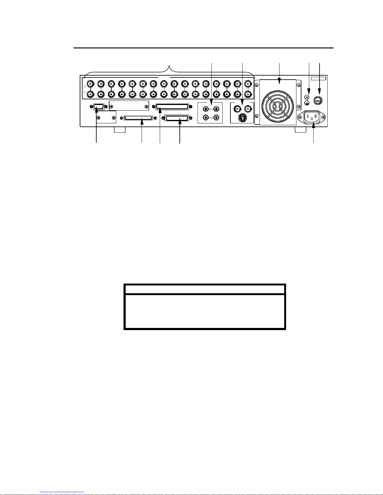
2-2. Rear Panel
Where:
① CAMERA 1−16
IN (Top row)
Used for video input connection. BNC type connectors.
OUT (Bottom row)
Used to output looped through input for connection to other system equipment. If no loopthrough
connection is made, connector will be automatically terminated with 75 Ω. BNC type connectors.
② AUDIO
IN (Top row)
Used to input unbalanced audio. RCA pin jack connectors.
OUT (Bottom row)
Used to output unbalanced -10dBu audio. RCA pin jack connectors.
Note
Input audio level must be set as MIC (microphone) or
LINE audio. (See sec. 6-11. Other Settings‘.)
RCA pin jack cables are the same type used for most
consumer stereo equipment.
③ MONITOR OUT
Used to view live cameras or playback video on connected monitor.
④ RS-232C
Used for RS-232C protocol control connection with controlling computer. 9-pin D-sub (female).
Note connector lock screws are inch type. (See sec. ‘3-2-1. RS-232C Connector’ for pin
assignments, and ‘Appendix. RS-232C Control Commands’ for control command codes and
related information.)
T4 .0A
S CS I 68pin(A m phenol)
F
U
S
E
PU SH
SER.No.
131 2 16153 6 107 8 9 1 1 1421
CAM ER A
O U T
A U TO
IN
M ON IT O R O UT
IN
R S-2 3 2C
OUT
AU DIO
L R
SCSI -A
R EM OT E
AL ARM
Y/ C
1 2
4 5
75Ω
AC 100-240 V - 50/6 0Hz IN
① ② ③ ⑧ ⑨ ⑩
④ ⑤ ⑥ ⑦ ⑪
(Continued following page.)
Page 13

7
⑤ SCSI-A
Used to externally expand the number of hard drives used for record and playback. (SCSI
termination connector received with CDR-16T must be connected here if no external
drives are connected.) (See sec. ‘3-2-4. SCSI Connector’ for pin assignments and other
details.)
⑥ REMOTE
Used for control connection with remote control device. 37-pin D-sub connector (female). Note
connector lock screws are inch type. (See sec. ‘3-2-2. Remote Connector’ for pin assignments
and other details.)
⑦ ALARM
U sed for external alarm input connection. 25-pin D-sub connector (female). Note connector lock
screws are inch type. (See sec. ‘ 3-2-3. Alarm Connector’ for pin assignments and other details.)
⑧ FAN
Used to air cool unit to prevent overheating. Do not block fan intake with other equipment or
objects. Front panel FAN ALM indicator will light red if fan operation fails.
⑨ Ground Terminal
Used to ground unit to protect operators against static electricity and electrical shock.
⑩ Fuse Holder
Should contain a 4.0A slow-blow fuse during operation to protect unit from over voltage
conditions. Note that fuse should only be changed or replaced by qualified personnel.
⑪ AC IN
Used for connection to AC power source via supplied accessory cord.
Page 14

8
3. Setup and Connection
3-1. Connection
3-1-1. Basic Connection
A basic connection example is given in the figure below.
T4 .0A
S CS I 68pin(A m phenol)
F
U
S
E
PU SH
SER.No.
131 2 16153 6 107 8 9 1 1 1421
CAM ER A
O U T
A U TO
IN
M ON IT O R O UT
IN
R S-2 3 2C
OUT
AU DIO
L R
SCSI -A
R EM OT E
AL ARM
Y/ C
1 2
4 5
75Ω
AC 100-240 V - 50/6 0Hz IN
ALARM device
CAMERA 1 – CAMERA 16
MIC
Termination
connector
Monitor
Must be connected if no
external HDD used.
(Supplied as accessory)
Page 15
9
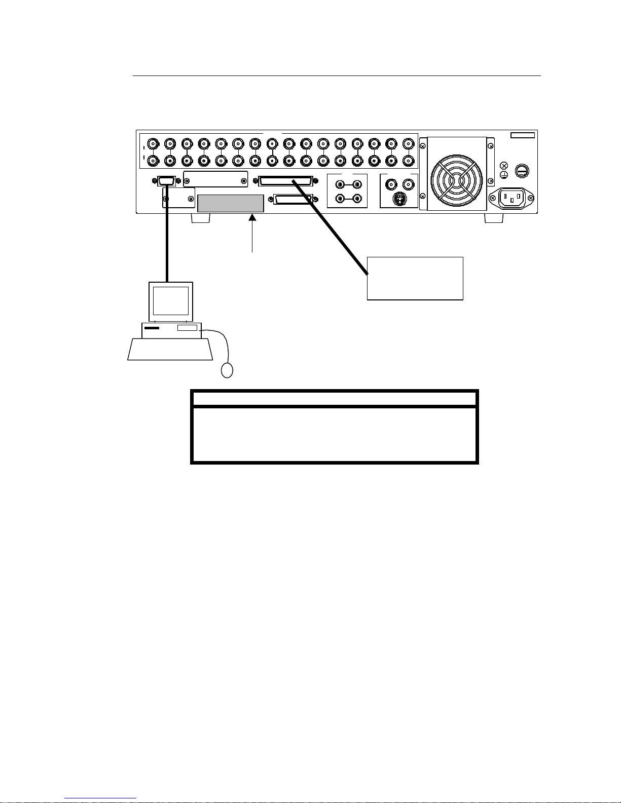
3-1-2. Computer / Remote Control Connection
The CDR-16T can be controlled either via a user fabricated remote control device or a
computer. See sec. ‘3-2-1. RS-232C Connector ’ when controlling via computer. See sec.
‘3-2-2. Remote Connector’ when controlling via remote device.
Important
Only one of the connections shown above is normally made
when configuring the CDR-16T for remote control.
Control via RS-232C connector requires use of command and
request codes given in the RS-232C appendix of this manual.
T4 .0A
S CS I 68pin(A m phenol)
F
U
S
E
PU SH
SER.No.
131 2 16153 6 107 8 9 1 1 1421
CAM ER A
O U T
A U TO
IN
M ON IT O R O UT
IN
R S-2 3 2C
OUT
AU DIO
L R
SCSI -A
R EM OT E
AL ARM
Y/ C
1 2
4 5
75Ω
AC 100-240 V - 50/6 0Hz IN
Remote Control
device
(User fabricated)
Computer
Termination
connector
Must be connected if no
external HDD used.
(Supplied as accessory)
Page 16

10
3-1-3. External Hard Drive Setup
It is possible to expand CDR-16T recording capacity by adding additional external hard
drives. Multiple external hard drives can be connected via the rear panel SCSI connector.
Connection is as illustrated below.
Important
It is possible to expand CDR-16T record capacity by
configuring up to 9 hard drives. Total array is limited to 9
drives, one internal drive + 8 external drives.
Set SCSI ID
The CDR-16T series internal HDD must be assigned SCSI ID number #0. Each
connected external hard drive must be assigned a different SCSI ID number other than #0
(no repeat numbers). Consult drive manual for ID setting procedure at drive unit. If ID settings
are wrong, operations cannot be properly performed.
Termination Connector
The last external HDD in the CDR-16T array must be terminated with the supplied accessory
SCSI termination connector. If last drive is not terminated, operational problems could result.
T4.0A
S CS I 68pin(Am phenol)
F
U
S
E
P US H
SER.No.
131 2 1 6153 6 107 8 9 11 1421
C AM ERA
O UT
A UTO
IN
M ON IT OR O UT
IN
R S-2 32 C
O U T
AUD IO
L R
SCSI- A
R EMO T E
ALARM
Y/C
1 2
4 5
75Ω
A C100- 240V - 50/60H z IN
External
hard disk
drive #1
External
hard disk
drive #2
Up to
external
hard disk
drive #8
Termination
connector
Required at last external HDD in
array. (Supplied as accessory)
Page 17
11
3-2. Connector Information
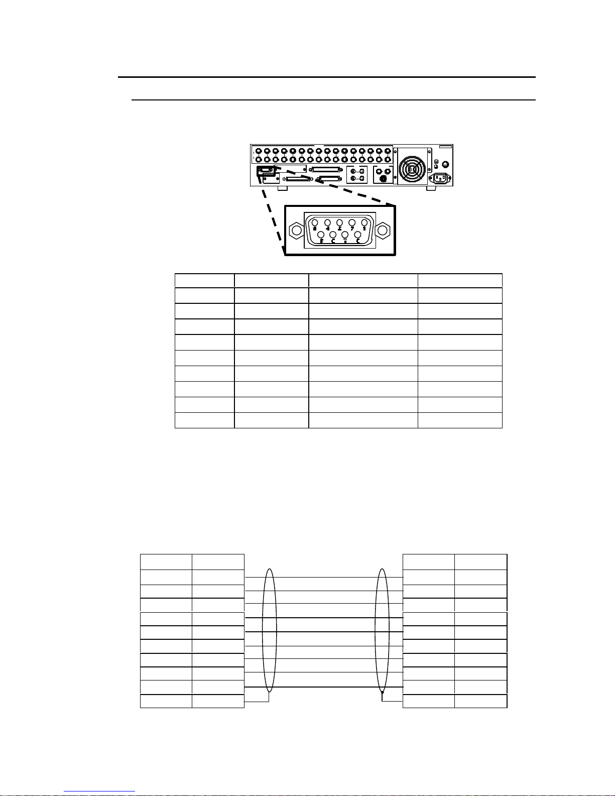
3-2-1. RS-232C Connector
See ‘Appendix. RS-232C Control Commands’ for command and request codes plus related
information.
u Pin Assignment
Pin No. Signal Remarks Direction
1 DCD Pins 4/6 repeat –
2 TxD Transmit data OUT
3 RxD Receive data IN
4 DTR Pins 1/6 repeat OUT
5 SG Signal ground –
6 DSR Pins 1/4 repeat IN
7 CTS Transmit ready IN
8 RTS Transmit request OUT
9 RI NC –
u Cable Wiring
An example of computer cable connection for control via RS-232C interface is shown below.
Note that example is based on the use of a PC-AT type (IBM / IBM format) computers that
use straight wired type cables. Cable wiring may differ for other computer models. Consult
your CBC supplier if you need a differently wired cable.
CDR-16T side
RS-232C connector
9-pin D-sub (female)
PC side
RS-232C connector
9-pin D-sub (female)
Signal Pin No. Pin No. Signal
DCD (I) 1 1 DCD (I)
TxD (O) 2 2 RxD( I)
RxD (I) 3 3 TxD (O)
DTR (O) 4 4 DTR (O)
SG (grd) 5 5 SG (grd)
DSR (I) 6 6 DSR (I)
CTS (I) 7 7 RTS (O)
RTS (O) 8 8 CTS (I)
RI (NC) 9 9 RI (NC)
Shell Shell
9-pin D-sub (male)
T4.0A
S CSI 68p in(Amp henol)
F
U
S
E
PUS H
SER.No.
1 312 16153 6 107 8 9 11 1421
CA MER A
OUT
AUT O
IN
MON ITOR OU T
IN
R S-23 2C
OU T
A UD IO
L R
SC S I-A
R EMOT E
A LA R M
Y/C
1 2
4 5
75Ω
AC100-240V - 50/60Hz IN
Page 18

12
3-2-2. Remote Connector
u Pin Assignment
Pin No. Function Pin No. Function
1 AUTO SEQ / ALARM RESET 20 VDD OUT
2 CAMERA 1 / A 21 SPLIT
3 CAMERA 2 / B 22 LIVE / PB
4 CAMERA 3 / C 23 REC
5 CAMERA 4 / D 24 STOP
6 CAMERA 5 / E 25 PLAY
7 CAMERA 6 / F 26 JOG
8 CAMERA 7 27 SHUTTLE
9 CAMERA 8 28 GND
10 CAMERA 9 / 4 – split 29 REC TALLY
11 CAMERA 10 / 5+1 – split 30 STOP TALLY
12 CAMERA 11 / 7+1 – split 31 PLAY TALLY
13 CAMERA 12 / 9 – split 32 JOG TALLY
14 CAMERA 13 / 8+2 – split 33 SHUTTLE TALLY
15 CAMERA 14 / 12+1 (1) – split 34 ADJUST IN
16 CAMERA 15 / 12+1 (2) – split 35 ADJUST OUT
17 CAMERA 16 / 16 – split 36 GND
18 DIAL – A (see page following) 37 GND
19 DIAL – B (see page following)
u Cable Connector / Control Signals
Pin core: DC-37PF-N (JAE)
Backshell: DC-C4-J12-S1 (JAE)
Signal: TTL negative pulse or make contact.
Important
Input signal pulse width must be more than 100ms and
interval between pulses more than 100ms.
(Continued following page.)
37-pin D-sub (female)
T4 .0A
SCS I 68p in(Amphe nol)
F
U
S
E
P USH
SER.No.
131 2 1 6153 6 1 07 8 9 11 1 421
C AM ER A
OU T
A UT O
IN
MON ITO R OU T
IN
R S -232 C
OUT
A U DIO
L R
S CS I-A
R E MOT E
A LA R M
Y/C
1 2
4 5
75Ω
A C10 0-2 40V - 50 /60H z IN
Page 19

13
Remote Control DIAL-A / DIAL-B Signal
Input signals below to remotely turn jog / shuttle dial.
Rotation
Direction
Control Signal for DIAL-A and DIAL-B
Rotate left
DIAL-B
(pin 19)
DIAL-A
(pin 18)
Rotate right
DIAL-B
(pin 19)
DIAL-A
(pin 18)
Note
DIAL-A and DIAL-B signal interval must be T ≧2ms (see
‘T’ above ) and have a 90° phase difference between them.
u REMOTE IN Circuit
Pins 1 – 19, 21 – 27 and pin 34 (ADJUST IN)
u TALLY / ADJUST OUT Circuit
Pins 29 – 33 (TALLY OUTS) and pin 35 (ADJUST OUT)
Input pin
GND pin
C-MOS
buffer
10kΩ
CDR-16T side
5V
0V
5V
0V
5V
0V
5V
0V
T
T
(Continued following page.)
Page 20
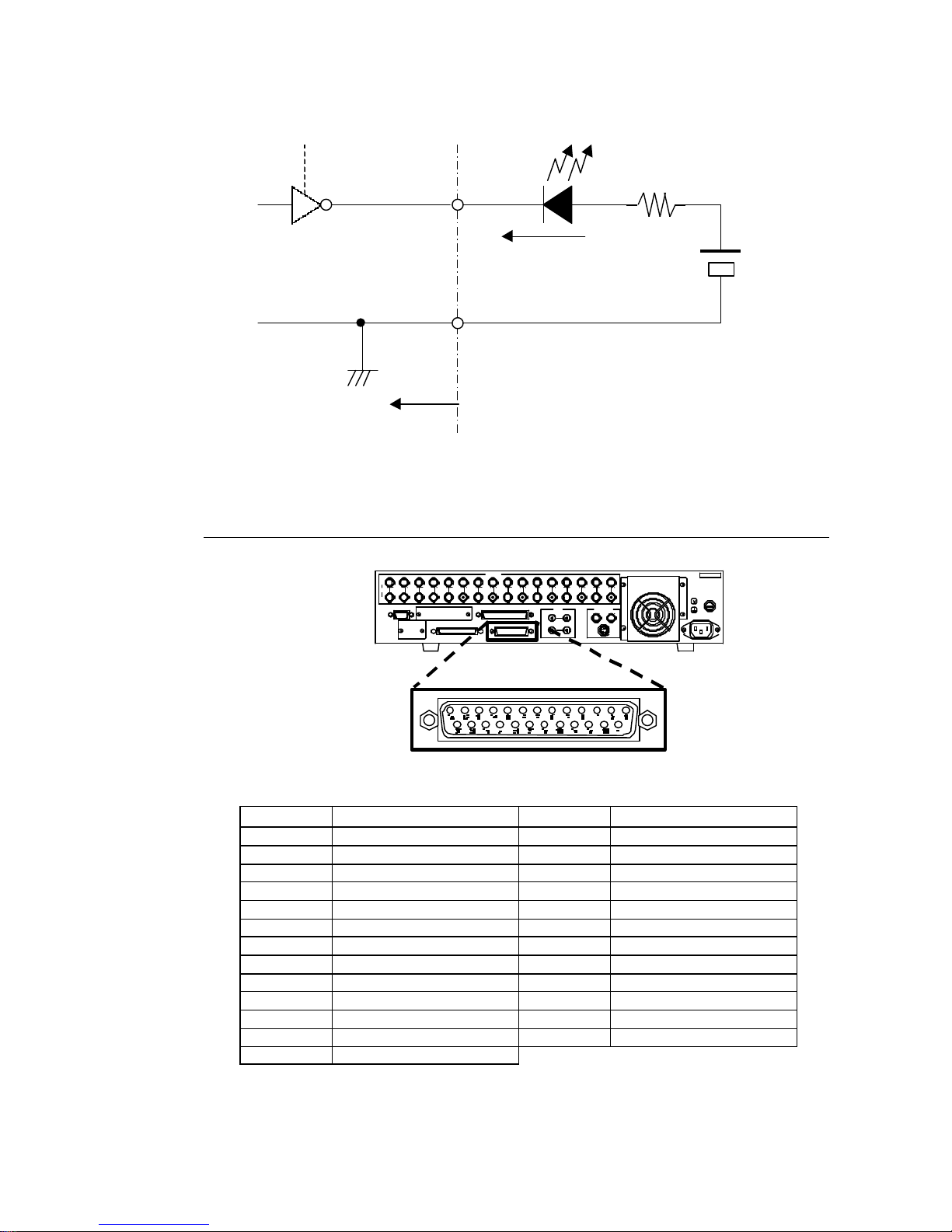
14
(※Choose resistor value according to type of LED configured in external circuitry.)
3-2-3. Alarm Connector
u Pin Assignment
Pin No. Function Pin No. Function
1 ALARM IN1 14 ALARM IN14
2 ALARM IN2 15 ALARM IN15
3 ALARM IN3 16 ALARM IN16
4 ALARM IN4 17 NC (Do not use)
5 ALARM IN5 18 NC (Do not use)
6 ALARM IN6 19 ALARM OUT (MAKE)
7 ALARM IN7 20 ALARM OUT (COM)
8 ALARM IN8 21 FAN ALARM (MAKE)
9 ALARM IN9 22 FAN ALARM (COM)
10 ALARM IN10 23 HDD ALARM (MAKE)
11 ALARM IN11 24 HDD ALARM (COM)
12 ALARM IN12 25 GND
13 ALARM IN13
Resistor
※
Output pin
Open collector
7406 (TTL)
max. 24VDC 40mA
+ 24VDC
max. power
40mA max.
LED
GND pin
CBC-16T side
25-pin D-sub (female)
T4 .0A
SCS I 68p in(Amphe nol)
F
U
S
E
P USH
SER.No.
131 2 1 6153 6 1 07 8 9 11 1 421
C AM ER A
OU T
A UT O
IN
MON ITO R OU T
IN
R S -232 C
OUT
A U DIO
L R
S CS I-A
R E MOT E
A LA R M
Y/C
1 2
4 5
75Ω
A C10 0-2 40V - 50 /60H z IN
(Continued following page.)
Page 21

15
u Cable Connector / Control Signals
Pin core: DB-25PF-N (JAE)
Backshell: DB-C4-J11-S1 (JAE)
Signal: TTL negative pulse or make contact.
Notes
Pins 1 – 16 are alarm signal inputs for each respective
camera (1 – 16).
Input signal pulse width must be more than 100ms.
u ALARM IN Circuit
Pins 1 – 16 (ALARM IN)
u ALARM OUT Circuit
Pins 19 – 24 (ALARM OUT)
(※Choose resistor value according to type of LED configured in external circuitry.)
Input pin
GND pin
C-MOS
buffer
10kΩ
CDR-16T side
MAKE
+ 24VDC
max.
power
100mA max.
Resistor
※
LED
COM
CDR-16T side
Max. 24VDC, 100mA
(contact closure)
Page 22

16
3-2-4. SCSI Connector
u Pin Assignment
Communication standard: Based on SCSI-2 (LVD 16-bit)
Pin
No.
Function Description
Pin
No.
Function Description
1 +DB12 Data bus, bit 12 35 -DB12 Data bus, bit 12
2 +DB13 Data bus, bit 13 36 -DB13 Data bus, bit 13
3 +DB14 Data bus, bit 14 37 -DB14 Data bus, bit 14
4 +DB15 Data bus, bit 15 38 -DB15 Data bus, bit 15
5 +DBP1 Data bus, parity bit 1 39 -DBP1 Data bus, parity bit 1
6 +DB0 Data bus, bit 0 40 -DB0 Data bus, bit 0
7 +DB1 Data bus, bit 1 41 -DB1 Data bus, bit 1
8 +DB2 Data bus, bit 2 42 -DB2 Data bus, bit 2
9 +DB3 Data bus, bit 3 43 -DB3 Data bus, bit 3
10 +DB4 Data bus, bit 4 44 -DB4 Data bus, bit 4
11 +DB5 Data bus, bit 5 45 -DB5 Data bus, bit 5
12 +DB6 Data bus, bit 6 46 -DB6 Data bus, bit 6
13 +DB7 Data bus, bit 7 47 -DB7 Data bus, bit 7
14 +DBP0 Data bus, parity bit 0 48 -DBP0 Data bus, parity bit 0
15 GND Ground 49 GND Ground
16 DIFFSNS 50 GND Ground
17
TERM
PWR
Power terminal 51
TERM
PWR
Power terminal
18
TERM
PWR
Power terminal 52
TERM
PWR
Power terminal
19 N / C 53 N / C
20 GND Ground 54 GND Ground
21 +ATN Message request 55 -ATN
Receive message
request
22 GND Ground 56 GND Ground
23 +BSY SCSI status flag 57 -BSY SCSI bus status flag
24 +ACK Reply for REQ signal 58 -ACK Reply for REQ signal
25 +RST Reset 59 -RST Reset
26 +MSG Message flag 60 -MSG Message flag
27 +SEL Selection 61 -SEL Selection
28 +CD
Control signal / identify
data
62 -CD
Control signal / identify
data
29 +REQ Transmission request 63 -REQ Transmission request
30 +IO Identify send direction 64 -IO Identify send direction
31 +DB8 Data bus, bit 8 65 -DB8 Data bus, bit 8
32 +DB9 Data bus, bit 9 66 -DB9 Data bus, bit 9
33 +DB10 Data bus, bit 10 67 -DB10 Data bus, bit 10
34 +DB11 Data bus, bit 11 68 -DB11 Data bus, bit 11
68-pin SCSI interface (female)
T 4.0A
SC SI 68p in(A mphe nol )
F
U
S
E
PUSH
SER.No.
1312 16153 6 107 8 9 11 1421
C A ME R A
OU T
AU T O
IN
M ON IT OR O U T
IN
R S -2 3 2C
OU T
A U D IO
L R
S C S I-A
R E M OT E
A L AR M
Y /C
1 2
4 5
75Ω
A C 100 -2 40V - 50/60 Hz IN
Page 23

17
4. Basic Operation
Note
Front panel operation buttons will be indicated in boxes
( ZOOM ) throughout this manual to make it easier to
distinguish between buttons and menus. ZOOM
(button) vs. ZOOM (menu).
4-1. Power ON / OFF
Ø CDR-16T will start uploading data from HDD memory when power is switched ON. Data load
completion takes approx. 30 sec. (see note below) and CONTROL group buttons will flash
until loading is completed.
Note
Data load completion time when 36GB internal HDD is
installed is approx. 30 sec. If your unit is a later internal
hard drive model and / or external drives configured, the
size and number of HDDs connected will determine how
long data load completion will take.
Ø Settings in operational memory are backed-up by an internal lithium battery having an approx.
life span of approx. 5 years (at 25° C). Battery will have to be replaced when the ‘BACKUP
ERROR’ message appears on your observation monitor. Consult your CBC supplier
regarding purchase of a replacement battery.
Ø Do not turn power OFF while record operations are in process. If power is turned OFF during
record, final frames will not record properly and / or will not be saved to disk.
Ø If a power failure occurs, POWER-ON-REC function will auto-restart record operations at the
point they were interrupted when power is again applied to the recorder. Record restart point
will also automatically record over final frames that were misrecorded at power loss.
Ø Do not move unit with power ON. Moving unit with power ON may cause damage to the hard
disk and / or loss of drive contents.
Page 24

18
4-2. Resetting to Factory Defaults
If you need to completely clear currently made operational settings, you can return recorder to
factory defaults and then make new settings.
◇ To return unit to factory default settings, proceed as below.
① The CDR-16T can be returned to factory defaults at any time by momentarily holding
AUTO (indicated below) depressed while switching ON power.
② Connected monitor will display ‘MEMORY CLEAR’ message while factory default settings
are being restored.
4-3. Screen Display
4-3-1. Full Screen
A basic full screen display example is given in the figure below. Item positions shown below
are factory default positions and should be visible if SUPER set to ON.
To set display (Super) ON or OFF, refer to sec. ‘7. Function Menu Settings. To select items to
be monitor displayed and recorded, refer to sec. ‘6-8. Display Mode’
(Continued following page.)
POWER
RESET
ALARM
BA
2AUTO 1
DRIVE1
FAN ALM
DRIVE2
POWER
ON
OFF
①
Page 25

19
Where:
① DATE / TIME
If playback view, shows date and time recording took place. If live view, shows current date
and time. See sec. ‘6-7. Date / Time Settings’ to set current date and time.
Also used to display error and operational messages. See sec. ‘4-3-3. Date / Time
Messages’.
② Camera Title
Shows title assigned to camera currently monitor displayed (live or playback). See sec. ‘6-6.
Title Settings’ to assign camera titles. If camera set to covert mode, ‘COVERT’ will be
displayed here instead of camera title. See sec. ‘6-1. Protect’ to set covert cameras.
③ Operational Status
Shows CDR-16T current operational status.
Where:
Display Description
REC Unit is recording and live view is monitor displayed.
STOP Live view is monitor displayed, unit not recording.
PLAY Playback view is monitor displayed, unit recording or not recording.
JOG
Jog search of playback material in process, unit recording or not
recording.
STL
Shuttle search of playback material in process, unit recording or not
recording.
(Continued following page.)
Camera 1
②
2001/10/2607:12:30 (FRI)
①
③ REC ERR ④
NO1: CONT (T) ⑤
⑥ TL:0.02S NOR ⑦
#00 0H00M00S ⑧
ALSVRM ⑨
Page 26

20
④ Error
ERR mark appears when CDR-16T operation is abnormal. Error message (hard disc or DVD
event error) will be displayed whenever HDD or DVD (optional) operation is incorrect. If
buzzer response set to ON, a tone will also sound when error occurs. (Push AUTO button to
stop buzzer sounding.)
⑤ Record Program
If playback view, shows record PROGRAM and REC MODE under which recording took
place. If live view, shows record PROGRAM and REC MODE under which recording will take
place when REC is pushed.
If live view, TIMER program set (not recording), shows TIMER (record PROGRAM). If live
view, TIMER program set (recording), shows record PROGRAM, REC MODE and (T) mark.
Where:
Display Description
NO1 – NO5 Program number (1-5) settings applied when R EC is pushed.
TIMER TIMER program is set but currently not recording.
PREALM Pre-alarm record. (See sec. ‘6-3-2. Pre Alarm Record’.)
1SHOT One shot record. (See sec. ‘6-3-3. One Shot Record’.)
CONT
Continuous record, alarm rec. mode set to OFF. (See sec. ‘6-3-
1. Continuous Record ’.)
A-LAST Continuous record, alarm rec. mode set to LAST CHANNEL.
A-SWIT Continuous record, alarm rec. mode set to SWITCHOVER.
A-ALL Continuous record, alarm rec. mode set to ALL CHANNEL.
A-PRI Continuous record, alarm rec. mode set to PRIORITY.
A-SEQ Continuous record, alarm rec. mode set to SEQUENCE.
(T) TIMER program is set and currently recording .
(※See sec. ‘6-4. Timer Program’ for details on TIMER program.)
⑥ Record Interval
If playback view, shows type of record interval and interval setting under which recording took
place. If live view, shows type of record interval and interval setting currently selected.
Where:
Display Description
TL Time-lapse
UD Update
Interval setting
See sec. ‘6-3-5. Regarding Timelapse / Update Mode Setting’
for information on settings available.
⑦ Record Quality
If playback view, shows record QUALITY under which recording took place. If live view,
shows record QUALITY currently selected.
(Continued following page.)
Page 27

21
Where:
Display Description
SUP Super (Best resolution on playback)
HI High
NOR Normal
LOW Low (Lowest resolution on playback)
(※See sec. ‘6-3. Record Programming’ for information on record QUALITY.)
⑧ HD Address
If playback view, shows hard disk ID no. and time point information. If live view (not recording),
shows hard disk ID no. and time point where previous recording stopped, next recording will
start. If live view (recording), shows hard disk ID no. and time point passage while recording.
Where:
Display Description
1H10M30S (counter) Relative time from HD start point
50% (percent)
Remaining percentage of HD available for recording
(whole numbers)
Note
Counter can be set to count up or count down mode. (See sec.
‘6-8. Display Mode’ for details on counter operation settings.
⑨ Alarm Index
If playback view, shows alarm index of image currently monitor displayed if image recorded
under alarm conditions.
If live view, alarm index (for type of alarm occurring) will appear when alarm occurs for
camera currently monitor displayed.
Where:
Display
Description
A Alarm Alarm signal input.
L video Loss Video signal loss.
S Sensor Alarm input from sensor card.
V image reVersion Image returns (to video loss channel) during record.
R Record start Time point where recording started.
M Manual
Alarm manually initiated. (REC button pushed during
recording.)
Note
V, R and M alarm indexes mark a single time point and
are only screen displayed for a short time. See sec. ‘7-2.
Index List Search’ for more information on alarms.
Page 28

22
4-3-2. Split Screen
A basic split screen display example is given in the figure below. Item positions shown below
are factory default positions and may be visible if SUPER set to ON. To set display ON or
OFF, refer to sec. ‘7. Function Menu Settings. To select items to be monitor displayed and
recorded, refer to sec. ‘9-8. Viewing Backup Data’.
Where:
Items ① – ③ are the same as when in full screen display. See sec. ‘ 4-3-1. Full Screen’.
Item ④ shows channel type (live, playback, covert or black) and number (1 – 16) of camera
currently monitor displayed. Note that these titles cannot be changed and user set camera
titles (name text lines) cannot be displayed during split display. Character codes shown
during split display are as indicated in the table below.
Display Description
L1 – L16 Live channels, camera 1 – 16
P1 – P16 Playback channels, camera 1 – 16
C1 – C16
Covert channels, camera 1 – 16 (See sec. ‘6-1. Protect’ to set covert
cameras.)
BLK Channel set to black. (Black also shown if channel missing.)
Note
See sec. ‘6-2. Split Position’ to assign cameras to
positions within split display.
L1 P1
C2 BLK
2001/03/10 07:12:30(SAT)
④
①
RM
#00 0H00M00S ③
ALSV
ALSV
ALSV
②
Page 29

23
4-3-3. Date / Time Messages
The following error and operational messages may be displayed in place of current (or
recorded) date and time during use of your CDR-16T.
Displayed Message Description / Action
NOW CHECKING HDD
Data uploading from HDD memory at power ON. Data
load completion time determined by size and number of
drives configured. See sec. ‘4-1. Power ON / OFF’.
POWER ON REC START
POWER-ON-REC function being performed. See sec.
‘4-1. Power ON / OFF’.
KEY PROTECT
This front panel button is locked out (disabled) from use.
See sec. ‘6-1. Protect’.
TOO FAST RECORDING
MODE
Record and playback cannot be performed at the same
time due to record interval. Record interval must be set
for more than 0.10 sec. See sec. ‘6-3-5. Regarding
Timelapse / Update Mode Setting’.
NOW SEARCHING
Other operations cannot be performed while searching
HDD. Perform other operations after search is complete.
See sec. ‘7-1. Date / Time Search’ and sec. ‘7-2. Index
List Search’.
TIMER PROGRAM
Programmed recording cannot start or stop when
settings are being made in TIMER PROGRAM. Finish
making settings and exit TIMER PROGRAM. See sec.
‘6-4. Timer Program’.
TIMER PROGRAM START Programmed recording starts.
TIMER PROGRAM STOP Programmed recording stops.
NO RECORDING CHANNEL
Cameras are not connected at rear panel, or not
assigned for recording in menus. Check connections at
rear panel and record channel menu settings. See sec.
‘6-3-4. Regarding Record Channel Setting’.
CANNOT FIND RECORD
HDD
HDD operations have been limited. Verify HDD is
available for recording in HDD menu. See sec. ‘7-3.
HDD Information’.
CANNOT FIND PLAYBACK
HDD
No material has been recorded to HDD, or operations
have been limited. Verify HDD is available for playback
in HDD menu. See sec. ‘7-3. HDD Information’.
ASSIGNING HDD USE
Other operations cannot be performed while HDD use is
being assigned. See sec. ‘6-10-1. Assign HDD Use’. Do
other operations after HDD assignment is complete.
Page 30

24
4-4. Full Screen Display Operations
Any single camera input can be viewed full screen size by selecting a camera button when in
OPERATION mode ( SPLIT not flashing).
u To View Live:
① Push LV/PB to lit to place recorder in live view mode. Live input from currently selected
camera (CAMERA SELECT 1 – 16) will be monitor displayed.
② Push any CAMERA SELECT 1 – 16 button to lit to view that camera input live. If set to
covert, or no camera input exists for selected camera number, black will be displayed at
observation monitor.
u To View Playback:
① Push LV/PB to unlit to place recorder in playback mode. Recorded material for currently
selected camera (CAMERA SELECT 1 – 16) will be monitor displayed.
② Push any CAMERA SELECT 1 – 16 button to lit to view recorded material for that camera.
If no recorded material exists for selected camera number, black will be displayed at
observation monitor.
Important
Covert channels will be displayed on the monitor as black
during playback or record (even though camera material
exists). To monitor view covert channels (live or
playback), covert setting must be set to OFF.
Record interval must be set to 0.10 sec. or more to use
simultaneous record and playback function. See sec.
‘6-3-5. Regarding Timelapse / Update Mode Setting ’ for
setting related information.
E F
1614 151312111091AUTO 8765432
CAMERA SELECT
A DCB
ALARM
RESET
SPLIT
MONITOR
*LV/PBCH Z OOM
①②
Page 31

25
4-4-1. Zoom
This feature allows the user to select and zoom in on specified part of full screen displayed
camera video. This function cannot be used during auto sequence operation or with split
screen displays. The procedure to initiate zoom operation and select area to view is as
follows.
Ø Refer to sec. ‘4-4. Full Screen Display Operations’ and select any single camera for full screen
display. Push ZOOM to lit. (Zoom screen may take approx. 2 sec. to appear.) The figure below
illustrates how zoom will occur. Note that the last zoom set area for selected camera will be
expanded approx. x2 size. (Dotted line in figure below shows default zoom area.)
(Continued following page.)
Original full screen
Last selected
(or default)
zoom area
Zoom screen
Line box gives
downscaled
full camera
view reference
Grey box mark
gives reference
for the area of
full screen now
expanded
① ②
③
FWDREV
ZO OMCH STOP JOG/SHTL
CONTROL
PLAY*LV/PB
MENU
MONITOR
SPLIT15 16
ENTER
FUNC REC
FRAME SEQ UENCE RECORDER FSR-100CDR-16T
Digital Recorder
CDR-16T
Digital Recorder
CDR-16T
Digital Recorder
CDR-16T
Digital Recorder
Page 32

26
u To x2 Expand a Different Area of the Camera View:
① The line box and gray box mark give the user an ‘on-screen’ reference for which area of
the camera video is now expanded. Push and hold either ↑ or ↓ direction buttons, or
→ direction button to select direction.
② Turn jog / shuttle dial to move gray box mark within the line box reference area to zoom
in another area of the video.
u To Quit ZOOM Mode:
① Push ZOOM again (to unlit) to exit ZOOM mode.
② Monitor screen returns to full screen view of selected camera.
4-4-2. Auto Sequence
You can automatically sequence through all inputs when operating in full screen display
mode (LIVE view channels only). How long individual cameras are displayed before
switchover to next camera occurs (dwell time) can be user set in sec. ‘’6-5. Auto Seq Time .
① Verify LV/PB to lit for live view mode, then push AUTO to lit.
② Currently selected camera video will switchover to next available camera at menu set
dwell time. Camera select button will light for camera input visible on screen.
③ Switchover of cameras will continue until LV/PB , SPLIT or any camera select number
button is pushed to change view mode.
Note
The following items will be automatically skipped during
auto sequence:
Inputs where no video is input (no signal connected).
Inputs where dwell time is set to 0 sec. (skipped).
Inputs set to covert.
E F
1614 151312111091AUTO 8765432
CAMERA SELECT
A DCB
ALARM
RESET
SPLIT
MONITOR
*LV/PBCH Z OOM
③
②
①
Page 33

27
Live Sequence Example:
CH1 – CH5, CH7 – CH12 = inputs connected
CH8, CH12 = skipped (dwell time set to 0 sec.)
CH5 = set to covert
CH6, CH13 – CH16 = no input connected
4-5. Split Screen Display Operations
Camera inputs can also be displayed in groups (split display mode).
① Verify LV/PB is lit for live view mode or LV/PB is unlit for playback mode.
② Push SPLIT, Button will flash for approx. 5 seconds.
③ Push any pattern select button while S PLIT is flashing to initiate split screen display
operation. (Available patterns are shown in sec. ‘4-5-1. Patterns’ following.)
④ If split pattern has more that one channel group, push S PLIT again to flashing indication.
⑤ Push button for required channel group while S PLIT is flashing. (Available channel groups
are shown in sec. ‘4-5-2. Channel Groups’ following.)
⑥ To change between live view mode and playback push LV/PB to lit / unlit.
⑦ To quit split display mode, push any camera select button when S PLIT is not flashing to go
to full screen view.
E F
1614 151312111091AUTO 8765432
CAMERA SELECT
A DCB
ALARM
RESET
SPLIT
MONITOR
*LV/PBCH Z OOM
①③④ ②
L1
L2
L3
L4
L7
L9
L10
L11
Channel / Dwell Time Setting
CH1 = 5 sec. dwell time
CH2 = 3 sec. dwell time
CH3 = 5 sec. dwell time
CH4 = 3 sec. dwell time
CH5 = Skipped (covert setting)
CH6 = Skipped (no input)
CH7 = 5 sec. dwell time
CH8 = Skipped (0 sec. dwell time)
CH9 = 5 sec. dwell time
CH10 = 3 sec. dwell time
CH11 = 5 sec. dwell time
CH12 = Skipped (0 sec. dwell time)
(Continued following page.)
Page 34

28
Important
Record interval must be set to 0.10 sec. or more to use
simultaneous record and playback function. See sec.
‘6-3-5. Regarding Timelapse / Update Mode Setting ’ for
setting related information.
4-5-1. Patterns
The figures below show the types of split display patterns available for selection. Note that
patterns have more than one channel group available. (See sec. ‘4-5-2. Channel Groups’
following.) Areas marked in gray indicate the main position in the pattern. Camera displayed
at this position can be changed with C H button. (See sec. ‘4-5-3. Changing Main Position
Camera’ following.) Camera displays at other positions can also be changed from within
menu. (See sec. ‘6-2. Split Position’ following.)
Important
Main positions for 9-split and 16-split do not support live /
playback mixed displays. (See sec. ‘4-5-3. Changing Main
Position Camera’ regarding live / playback mixed displays.
4 ( 9 ) 5+1 ( 10 ) 7+1 ( 11 ) 9 ( 12 )
8+2 ( 13 ) 12+1 (1) ( 14 ) 12+1 (2) ( 15 ) 16 ( 16 )
Page 35

29
4-5-2. Channel Groups
Default channel groups for each split screen pattern are as indicated below. BL in figures
below indicates black screen displayed at that position. If no video is input, screen will be
black. To change channels assigned to positions within any selected group, see sec. ‘ 6-2.
Split Position’.
u 4-Split (6 channel groups available)
u 5+1-Split (4 channel groups available)
u 7+1-Split (3 channel groups available)
(Continued following page.)
A
1 2
3 4
B
5 6
7 8
C
9 10
11 12
D
13 14
15 16
E
BL BL
BL BL
F
BL BL
BL BL
(Where BL = Black only displayed.)
A
2
1
3
4 5 6
B
8
7
9
10 11 12
C
14
13
15
16 BL BL
D
BL
BL
BL
BL BL BL
(Where BL = Black only displayed.)
C
BL
BLBL
BL
BL BL BL BL
B
10
119
12
13 14 15 16
A
2
31
4
5 6 7 8
(Where BL = Black only displayed.)
Page 36

30
u 9-Split (2 channel groups available)
u 8+2-Split (2 channel groups available)
u 12+1-Split (1) (2 channel groups available)
u 12+1-Split (2) (2 channel groups available)
u 16-Split (2 channel groups available)
A
1 2 3
4 5 6
7 8 9
B
10 11 12
13 14 15
16 BL BL
(Where BL = Black only displayed.)
A
1 2
3 4 5 6
7 8 9 10
B
11 12
13 14 15 16
BL BL BL BL
(Where BL = Black only displayed.)
A
2 3
4 5
6 7 8 9
10 11 12 13
B
15 16
BL BL
BL BL BL BL
BL BL BL BL
1
14
(Where BL = Black only displayed.)
A
2 3 4 5
6 7
8 9
10 11 12 13
B
15 16 BL BL
BL BL
BL BL
BL BL BL BL
1
14
(Where BL = Black only displayed.)
A
1 2 3 4
5 6 7 8
9 10 11 12
13 14 15 16
B
BL BL BL BL
BL BL BL BL
BL BL BL BL
BL BL BL BL
(Where BL = Black only displayed.)
Page 37

31
4-5-3. Changing Main Position Camera
When in split screen mode, camera displayed at main position can be changed at any time.
Change will be saved when screen is exited. To change channels assigned to other positions
see sec. ‘6-2. Split Position’.
① Verify monitor displays a split screen view. (Push SPLIT and select pattern and group.)
② Push CH . Button will flash for approx. 5 seconds.
③ Push CAMERA SELECT button for desired channel while CH is flashing. Or push CH
again, each push will change main position by one input channel.
Note
New camera channel assignment for main position will be
saved on channel group exit. Next time channel group is
displayed, most recently made user assignment will
appear at main position.
u Example 1:
Channel group A main position is changed from CH1 to CH10.
① Push LV/PB to lit for live view. (Push to unlit for
playback video.)
② Push SPLIT to flashing.
③ Push 9 for 4-split screen.
④ Push SPLIT to flashing.
⑤ Push 1 to select channel group A.
Then:
⑥ Push CH to flashing.
⑦ Push 10 to select camera 10 for new main
position camera.
Next time 4-split screen group A is recalled, the group
will be displayed with the new channel assignment just
made appearing at the main position.
E F
1614 151312111091AUTO 8765432
CAMERA SELECT
A DCB
ALARM
RESET
SPLIT
MONITOR
*LV/PBCH Z OOM
①③ ②
Default A
1 2
3 4
Changed A
10 2
3 4
Recalled A
10 2
3 4
Page 38

32
u Example 2
Channel group A main position is changed from CH10
to black.
① Repeat steps ① – ⑤ in example 1 to recall split
screen.
Then:
② Push CH to flashing.
③ Push ZOOM.
Next time 4-split screen group A is recalled, the
group will be displayed with a black screen
appearing at the main position.
u Example 3:
Channel group A main position is changed from CH10 to
CH6 playback. (All channel groups in this split pattern
changed to CH6 playback.)
① Repeat steps ① – ⑤ in example 1 to recall split
screen.
Then:
② Push CH to flashing.
③ Push LV/PB to unlit for playback video.
④ Push CH to flashing.
⑤ Push 6 to select camera 6 playback for new main position camera.
Next time any 4-split screen group is recalled, the group will be displayed with the new
playback channel assignment just made appearing at the main position.
Regarding Live / Playback Mixed Display Patterns
If main position in any live channel group is changed from live to playback video, all
channel groups for that split pattern will display the same channel.
If main position in any playback channel group is changed from playback video to
live, all channel groups for that split pattern will display the same channel.
Note
Main positions for 9-split and 16-split do not support live /
playback mixed display patterns. All positions are either
live or playback only.
Recalled A
10 2
3 4
Changed A
BL 2
3 4
Recalled A
10 2
3 4
Changed A
P6 2
3 4
Page 39

33
4-5-4. Channel Group Auto Sequence
When camera inputs are split screen displayed, you can automatically sequence through all
channel groups available for the currently selected split pattern (LIVE view channels only). If
all positions within any given channel group are displayed as black (or have no input), group
will be automatically skipped. For information on groups available for split patterns, see sec.
‘4-5-2. Channel Groups’. For information on changing dwell time, see sec. ‘6-5. Auto Seq
Time’.
① Verify monitor displays split screen display. (Push S PLIT and select pattern and group.)
② Push AUTO to lit.
③ Currently selected channel group will switchover to next available channel group at
menu set dwell time. Camera select button (A – F) will light for channel group currently
screen displayed. How many channel groups (A – F) are available for selected pattern
will depend on type of pattern.
④ Switchover of cameras will continue until LV/PB , SPLIT or any camera select number
button is pushed to change view mode.
Notes
The following positions will be displayed as black during auto
sequence:
Inputs where no video is input (no signal connected).
Inputs set to covert.
Inputs set to display black.
Channel groups will be automatically skipped during auto
sequence if every position in channel group is displayed as black.
(One of the 3 conditions listed above exists for all camera
channels in the group. See ‘Important’ note box on following
page.)
Important
A dwell time setting of 0 sec. for full screen channels will effect
split screen auto sequence as follows:
If channel group has at least 1 other input (full screen dwell time
not set to 0 sec.) not displayed as black.
Channel group auto sequences according to split screen dwell
time setting. Channel set to 0 sec. (full screen dwell time) is
displayed.
If channel group has all other inputs displayed as black,
Channel group automatically skipped during auto sequence.
(Continued following page.)
E F
1614 151312111091AUTO 8765432
CAMERA SELECT
A DCB
ALARM
RESET
SPLIT
MONITOR
*LV/PBCH Z OOM
③②
①
Page 40

34
u Example: 4-split A – F channel groups selected. Settings are as follows:
Channel Input Covert
Dwell time
(Full screen)
Display Group
CH1 = YES OFF 5 sec. CH1
CH2 = YES OFF 3 sec. CH2
CH3 = YES OFF 5 sec. CH3
CH4 = YES OFF 3 sec. CH4
Group A
Auto Sequenced
CH5 = YES ON 5 sec. Black
CH6 = NO OFF 3 sec. Black
CH7 = YES OFF 5 sec. CH7
CH8 = YES OFF 0 sec. CH8
Group B
Auto Sequenced
CH9 = YES OFF 5 sec. CH9
CH10 = YES OFF 3 sec. CH10
CH11 = YES OFF 5 sec. CH11
CH12 = YES OFF 0 sec. CH12
Group C
Auto Sequenced
CH13 = YES OFF 0 sec. Black
CH14 = YES ON 3 sec. Black
CH15 = NO OFF 5 sec. Black
CH16 = NO OFF 3 sec. Black
Group D
Skipped
NO No channels assigned Black
Group E
Skipped
NO No channels assigned Black
Group F
Skipped
u Display will be as shown below:
A
L1 L2
L3 L4
B
C5
Black
Black
L7
L8
0 sec.
C
L9 L10
L11
L12
0 sec.
D (skipped)
L13
0 sec.
C14
Black
Black Black
E (skipped)
Black Black
Black Black
F (skipped)
Black Black
Black Black
(Continued following page.)
Page 41

35
Live / Playback Mixed Sequence:
If main position in live view group has been assigned for playback use, playback screen will
not change during auto sequence. Only live channels will be changed (updated) during auto
sequence mode.
u Example 1: LV/PB to lit for live view. 4-split A – F channel groups.
Main screen = playback (PB) material
Inputs connected = CH1 – CH5, CH7 – CH12 (appearing in groups A – C)
No input connected = CH6, CH13 – CH16 (Since all positions within groups D, E and F have
no inputs these groups are skipped.)
Likewise, if main position in playback group has been assigned for live use, only main
position will be changed (updated) during auto sequence mode. Remaining positions are
playback and views will not change during auto sequence. Switchover will occur based on
dwell time settings set for full screen channels. (See sec. ‘6-5. Auto Seq Time ’.)
u Example 2: LV/PB to unlit for playback. 4-split channel group A selected.
Main position = live material
Inputs connected = CH1 – CH5, CH7 – CH12
Skipped (dwell time set to 0 sec.) = CH8, CH12
Covert (skipped) = CH5
Live A
PB L2
L3 L4
Live B
PB Black
L7 L8
Live C
PB L10
L11 L12
PB (groupA)
L1 PB 2
PB 3 PB 4
L2 PB 2
PB 3 PB 4
L3 PB 2
PB 3 PB 4
L4 PB 2
PB 3 PB 4
L7 PB 2
PB 3 PB 4
L9 PB 2
PB 3 PB 4
L10 PB 2
PB 3 PB 4
L11 PB 2
PB 3 PB 4
Channel / Dwell Time Setting
(full screen dwell time setting)
CH1 = 5 sec. dwell time
CH2 = 3 sec. dwell time
CH3 = 5 sec. dwell time
CH4 = 3 sec. dwell time
CH5 = Skipped (covert setting)
CH6 = Skipped (no input)
CH7 = 5 sec. dwell time
CH8 = Skipped (0 sec. dwell time)
CH9 = 5 sec. dwell time
CH10 = 3 sec. dwell time
CH11 = 5 sec. dwell time
CH12 = Skipped (0 sec. dwell time)
No input connected = CH6, CH13 – CH16
Page 42

36
4-6. Record / Playback
4-6-1. Manual Record
Note that settings made in menus will affect how record is performed when the procedure
below is used. See sec. ‘6-3. Record Programming’ for settings that need to be made prior to
record operations. See sec. ‘5. Using Menus’ to select which group of record settings
(program) to use when recording with this procedure.
① To start recording, push R EC to lit.
② To stop recording, push and hold S TOP
button approx. 2 sec. R EC goes to unlit
and rec-cord operation is exited.
Manual alarm index
Manual alarm indexes can be used to create alarm points that can later be recalled using the
INDEX LIST SEARCH function. To create a manual alarm index, push REC (one time for
each point you want to create) while recording. For information about other alarm indexes
see sec. ‘7-2. Index List Search’.
Important
If TIMER program has been selected at REC PROGRAM
in the FUNCTION menu, pushing R EC will not start
record operation. For information on timed record
operations see sec. ‘4-6-2. Auto Record’.
Record interval must be set to 0.10 sec. or more to use
simultaneous record and playback function. See sec.
‘6-3-5. Regarding Timelapse / Update Mode Setting ’ for
setting related information.
4-6-2. Auto Record
To use auto record function, record start / stop times must first be programmed in the TIMER
menu, then TIMER must be selected in the FUNCTION menu as the REC PROGRAM to be
applied.
See sec. ‘6-3. Record Programming’ for menu setups required and other information related
to record operations. See sec. ‘6-4. Timer Program ’ for information related to setting program
times for auto time record (timer program). See sec. ‘5. Using Menus’ for information related
to selecting which timer program to use.
F UNC
ENT ER
MENU
PLAY
CONTROL
JOG/SHTLSTO P
①
②
Page 43

37
4-6-3. Playback and Search
Important
Record interval must be set to 0.10 sec. or more to use
simultaneous record and playback function. See sec.
‘6-3-5. Regarding Timelapse / Update Mode Setting ’ for
setting related information.
u To Start Playback of Recorded Material:
① Push LV/PB to unlit, then push PLAY to lit. Playback of recorded material will begin.
② Select full screen camera (see sec. ‘4-4. Full Screen Display Operations’) or split screen
pattern and group (see sec. ‘4-5. Split Screen Display Operations’) for view.
Important
When P LAY is pushed, playback will start from the
timeline position where previously stopped. (On first use
playback will start at the beginning of the recorder
timeline.)
u To Stop Playback / Start Jog Search of Recorded Contents:
① Push JOG/SHTL once to lit. PLAY goes unlit. Playback stops.
② Turn jog / shuttle dial right to jog video forward 1 frame at a time, turn left to jog in
reverse.
u To Start Shuttle Search of Recorded Contents:
① Push JOG/SHTL a second time (still lit). PLAY goes to lit again.
② Turn jog / shuttle dial right to forward shuttle search, left to shuttle search in reverse.
Note that search speed will be determined by how far dial is turned left or right . Shuttle
search speed range is from x 1/64 to x 128 of real time.
③ Push JOG/SHTL again to stop shuttle search operation.
①
④
② ③
CDR-16T
D igita l R eco rd e r
REV FWD
Z O OMC H ST OP JO G/ SHT L
CONTROL
PL AY*L V/PB
M ENU
MONITOR
SPL IT7 8 9 10 1 1 1 2 1 3 1 514 1 6
ENT ER
F UN C RE C
Page 44

38
5. Using Menus
There are two key menu displays, which are used to make all the main operational setup and
programming during CDR-16T use; MAIN and FUNCTION.
5-1. Accessing MAIN Menu
The MAIN Menu and it’s related Sub Menus are used to make all general operational settings
and to display related settings. Push small non-metallic tool into Main Menu hole to push access
Main Menu button.
When MENU is pushed, a MAIN (top) menu similar to below will be monitor displayed.
u Accessing Sub Menus From Main Menu
There are 3 ways you can select a sub menu from this menu.
Ø
Procedure 1: (dial / ENTER )
Turn jog / shuttle dial to move selection cursor in menu to required item. Push ENTER to go to
sub menu or exit.
Ø
Procedure 2: (arrow buttons ↓ / ↑ / ENTER )
Push arrow buttons to move selection cursor in menu to required item. Push ENTER to go to
sub menu or exit.
Ø
Procedure 3: (1 button access) This procedure can only be used in menu shown above.
Push CAMERA SELECT button with matching number.
Example: Push 2 (SPLIT POSITION), to go to ‘SPLIT POSITION’ sub menu.
(Continued following page.)(Continued following page.)
MAIN MENU
→ 1 PROTECT
2 SPLIT POSITION
3 RECORD
4 TIMER PROGRAM
5 AUTO SEQ TIME
6 TITLE
7 DATE / TIME
8 DISPLAY MODE
9 ALARM / LOSS / SENSOR
10 HDD
11 OTHER
12 SYSTEM
13 SENSOR
14 DVD
15 EXIT
Cursor selected
Page 45

39
u Sub Menu Example (when ‘3 RECORD’ selected in MAIN MENU)
u Accessing Sub Menus
There are 2 ways you can select a sub menu in this type of menu.
Ø
Procedure 1: (dial / ENTER )
Turn jog / shuttle dial to move selection cursor in menu to required item. Push ENTER to go to
sub menu.
Ø
Procedure 2: (arrow buttons ↓ / ↑ / ENTER )
Push arrow buttons to move selection cursor in menu to required item. Push ENTER to go to
sub menu.
[RECORD]
PROGRAM – NO.1
REC MODE – CONTINUOUS
QUALITY – NORMAL
AUDIO – OFF
REC CHANNEL
NORM=4 FAST=2
TIMELAPSE MODE 0.10SEC
UPDATE (NORM) = 0.80SEC
UPDATE (FAST) = 0.40SEC
TOTAL REC TIME= 30 H52M
ALARM REC MODE –SEQUENCE
ALARM QUALITY – SUPER
ALARM SEQ REC
SET EXIT
Lower sub menus
Parameter
settings
(Highlighted
gray for
example
purposes.)
Information
based on
sub menu
parameter
settings
(Cannot be
changed.)
(‘=’ mark items above = Information, ‘–‘ mark = Parameter setting
Page 46

40
u Changing Menu Parameter Settings
To select and modify settings in this type of menu use the front panel controls. Standard button
use is as listed in the following chart. (Parameter settings in this sub-section are highlighted gray
for example purposes only.)
Button Description
↓ Moves to sub menu / decrements parameter with each push.
↑ Moves to higher menu / increments parameter with each push.
Dial Scrolls through possible sub menu selects / menu parameters.
→
Scrolls through possible settings by one each push
(changes setting (in gray area) currently selected).
→ + Dial
Scrolls through possible settings at high speed
(changes setting (in gray area) currently selected).
Sub menu selected Goes to selected sub menu.
Parameter setting
selected
Action depends on menu / parameter
setting selected. Possible actions are:
Goes to information menu (ENTER again to
return to previous menu).
Inputs parameter settings and returns user
to previous menu.
Starts action (i.e. format).
No action performed.
WARNING
on screen
Returns user to previous menu.
SET selected
Inputs parameter settings and returns user
to previous menu.
Sub
menu
Cancels parameters and returns
user to previous menu.
ENTER
EXIT selected
Main
menu
Exits main menu.
MENU
Exits function menu (if parameter settings not input, settings are
canceled).
Note
Whenever a menu uses other panel controls, or buttons
listed here have different functions, a chart similar to
above will be included with the menu explanation.
u Procedure to Change Menu Parameter Settings
① Turn jog / shuttle dial or push arrow buttons to move selection cursor in menu to required
item.
② Push → or → + Dial to change setting.
③ Turn jog / shuttle dial or push arrow buttons to move selection cursor in menu to SET.
④ Push ENTER to input parameter settings and exit function menu or return to previous
menu if in sub menu.
(Continued following page.)
Page 47

41
Important
See sec. ‘6. MAIN Menu Settings’ for details on
operations set / performed here. If no menu selection is
made within 1 min., recorder will automatically return to
normal operation. (Menu no longer displayed.)
5-2. Accessing Function Menus
The Function Menu and it’s related Sub Menus are used to search recorded material, program
timer settings and select what information is displayed on screen (superimposed)
When FUNC is pushed, a menu similar to below will be monitor displayed.
u Accessing Sub Menus
There are 2 ways you can select a sub menu in this function menu.
Ø
Procedure 1: (dial / ENTER )
Turn jog / shuttle dial to move selection cursor in menu to required sub menu. Push ENTER to
go to that sub menu.
Ø
Procedure 2: (arrow buttons ↓ / ↑ / ENTER )
Push arrow buttons to move selection cursor in menu to required sub menu. Push E NTER to go
to sub menu.
u Changing Menu Parameter Settings
To select and modify settings in this type of menu, use the front panel controls. Standard button
use is as listed in the chart in 5-1. Accessing MAIN Menu previously.
Ø Procedure to Change Menu Parameter Settings
① Turn jog / shuttle dial or push arrow buttons to move selection cursor in menu to required
item.
② Push → or → + Dial to change setting.
(Continued following page.)
[FUNCTION]
DATE/TIME SEARCH
INDEX LIST SEARCH
HDD INFORMATION
REC PROGRAM – NO.1
SUPER – ON
POWER ON/OFF LOG
USER BACKUP DVD
DVD INDEX SEARCH
PLAYBACK DRIVE-HDD
DVD INFORMATION
Sub-menus
Parameter
settings
(Highlighted gray
for example
purposes.)
Page 48

42
③ Turn jog / shuttle dial or push arrow buttons to move selection cursor in menu to SET.
④ Push ENTER to input parameter settings and exit function menu or return to previous
menu if in sub menu.
Important
See sec. ‘7. Function Menu Settings’ for details on
operations set / performed here. If no menu selection is
made within 1 min., recorder will automatically return to
normal operation. (Menu no longer displayed.)
6. MAIN Menu Settings
To access MAIN menu, push MENU . Bottom indicator should light and MAIN menu below should
appear on monitor. See sec. ‘5-1. Accessing MAIN Menu’ for information on making menu
selections.
Note
MENU mode cannot be accessed if CDR-16T is in
FUNCTION mode. ( FUNC to lit.)
Where:
① PROTECT
Allows user to input password and set password lock ON / OFF. See sec. ‘6-1. Protect ’.
FUNC
ENT ER
MENU
PLAY
CONTROL
JOG /SHTLSTOP
Cursor selected
MAIN MENU
→ 1 PROTECT
2 SPLIT POSITION
3 RECORD
4 TIMER PROGRAM
5 AUTO SEQ TIME
6 TITLE
7 DATE / TIME
8 DISPLAY MODE
9 ALARM / LOSS / SENSOR
10 HDD
11 OTHER
12 SYSTEM
13 SENSOR
14 DVD
15 EXIT
(Continued following page.)
Page 49

43
② SPLIT POSITION
Allows user to change channels assigned to each position in each split pattern / channel group
display. See sec. ‘’6-2. Split Position.
③ RECORD
Allows user to make settings related to record operations. See sec. ‘6-3. Record Programming’.
④ TIMER PROGRAM
Allows user to set start and stop times for auto time record operations. See sec. ‘6-4. Timer
Program’.
⑤ AUTO SEQ TIME
Allows user to make settings related to auto sequencing operations. See sec. ‘6-5. Auto Seq
Time’.
⑥ TITLE
Allows user to input ID title of up to 16 characters for each camera channel. See sec. ‘6-6. Title
Settings’.
⑦ DATE / TIME
Allows user to set date and time related parameters. See sec. ‘6-7. Date / Time Settings’
⑧ DISPLAY MODE
Allows user to make settings related to how and where information is displayed at observation
monitors. See sec. ‘6-8. Display Mode’.
⑨ ALARM / LOSS / SENSOR
Allows user to make settings related to alarm input and alarm responses. See sec. ‘6-9. Alarms.
⑩ HDD
Allows user to make settings related to hard disk usage. See sec. ‘6-10. HDD’.
⑪ OTHER
Allows user to make the following settings for other misc. items such as baud rate, loop record,
color display, disk format, and event clear. See sec. ‘6-11. Other Settings’.
⑫ SYSTEM
Shows user information about software and options used in their system. See sec. ‘6-12.
System Information’.
⑬ SENSOR
Allows user to make settings related to sensor usage. See sec.’8. Sensor Operation’.
⑭ DVD
Allows user to make settings related to sensor usage. See sec.’9. DVD Option ’.
⑮ EXIT
Exits MAIN menu and returns user to operation mode. MAIN menu can also be exited by
pushing MENU again.
Page 50

44
u If PASSWORD LOCK is Set to ON:
Password screen shown below will appear when MENU is pushed. The correct password must
be input to access MENU mode. The MAIN MENU screen will only appear if the input password
is correct. Unit will return to operation mode if incorrect password is input.
u Special Button Functions:
Button Description
CH1 – CH13 Goes to sub menu
CH1 – CH9 Used to input password
6-1. Protect
See sec. ‘5-1. Accessing MAIN Menu’ for information on making menu selections.
[PASSWORD]
INPUT PASSWORD
PASSWORD – – ****
PUSH CAMERA SELECT BUTTON 1 – 9
⑤
①
②
③
④
[PROTECT]
PASSWORD‑‑1234
PASSWORD LOCK –ON
KEY PROTECT –OFF
COVERT –ON
CH1—O N CH2—OFF CH3—OFF
CH4—O N CH5—OFF CH6—OFF
CH7—OFF CH8—OFF CH9—OFF
CH10‑OFF CH11‑OFF CH12‑OFF
CH13‑OFF CH14‑OFF CH15‑OFF
CH16‑OFF
SET EXIT
Page 51

45
STOP JOG/SHTL
CONTROL
PLAY
ENTER
FUNC
Where:
① PASSWORD
Sets a four-digit password to be used to access MENU mode. Use CAMERA SELECT number
buttons 1 − 9 to enter password.
② PASSWORD LOCK
Sets if password required to access MENU mode and change operational settings.
OFF No password required. (Factory setting.)
ON Password required. See sec. ‘6. MAIN Menu Settings’.
Important
Do not forget your password. If password is forgotten,
resetting to defaults will clear password setting and allow
you to access MENU mode.
Note that resetting to defaults will also clear all settings
currently made. See sec. ‘4-2. Resetting to Factory
Defaults’ to reset defaults.
③ KEY PROTECT
Sets which front panel buttons are locked out (disabled) from use.
OFF All front panel buttons can be used. (Factory setting).
CONTROL
Control group buttons only (shown below) locked out.
ALL Only MENU button can be used. All other buttons locked out.
④ COVERT
Sets whether camera channels set to ON at ⑤ appear at the display monitor or not. (Camera
hidden from observation during live or playback, full or split view.)
OFF All cameras displayed at monitor as normal. (Factory setting.)
ON Black displayed at monitor for channels set to ON at ⑤ in this menu.
Important
Covert channels will be monitor displayed when alarm is
input and ALARM DISPLAY in ALARM / LOSS menu is
ON. See sec. ‘6-9. Alarms ’.
To view covert channels live or playback recorded
material, covert setting must be set to OFF.
(Continued following page.)
Page 52

46
⑤ Covert camera select
Setting independently made for each camera. Settings valid only when ④ set to ON.
OFF Camera video displayed at monitor.
ON Black displayed at monitor.
u Special Button Functions:
Button Description
CH1 – CH9 Used to input password
6-2. Split Position
Allows user to assign which camera channels appear at each position in split pattern / channel
group display. Note that the main position in any split display can be changed at any time
independent of this setting. See sec. ‘4-5-3. Changing Main Position Camera’ for details.
Split displays each have one main position that can be used for live view or playback of any
panel selected camera. Other positions will display cameras assigned in this menu. Live at main
and playback at other positions and vise versa display is possible. (Not supported by 9 and
16-split displays.) See sec. ‘5-1. Accessing MAIN Menu’ for information on making menu
selections.
P1 L2
L3 L4
Where:
① Pattern / group indication
Selects split pattern and channel group to which channel assignments made here are applied.
Selection can be made with → button or S PLIT and appropriate split pattern and channel group
buttons. Monitor will display selected split pattern and channel group.
② Main position channel select
Shows channel currently assigned to main position. Live or playback can also be selected at this
position (except 9 and 16-split displays).
LIVE 4/A
SET EXIT
①
②
③
(Continued following page.)
Page 53

47
③ Channel select
Shows channel currently assigned to split position. View (live or playback) assigned here must
match view assigned at ①.
L: Channel set to live view. Select from L1 – L16 (set with CH 1 – 16 button or → ) and LBK (live
black channel, set with ZOOM button).
P: Channel set to playback view. Select from P1 – P16 (set with CH 1 – 16 button or → ) and
PBK (playback black channel, set with ZOOM button).
u To Change Assigned Channels:
① Select split pattern and channel group you want channel assignment settings applied to.
② Move cursor to split position where assignment is to be made.
③ Select channel to be assigned.
④ Move cursor to next split position and repeat step ③.
⑤ Move cursor to SET, then push E NTER to save and exit. Or move to EXIT and push
ENTER to cancel settings just made and return to MAIN menu.
u Regarding Live / Playback Mixed Display Patterns
If main position in any live channel group is changed from live to playback video, all channel
groups for that split pattern will have the same display.
If main position in any playback channel group is changed from playback video to live, all
channel groups for that split pattern will have the same display.
Note
Main positions for 9-split and 16-split do not support live /
playback mixed display patterns. (All positions must be to
live or playback only.)
u Special Button Functions:
Button Description
At ① Selects live or playback view for split pattern.
LV/PB
At ② Selects live or playback view for main position.
CH9 – CH16 At ① Selects split pattern.
CH1 – CH6 At ① Selects channel group.
CH1 – CH16 At ②, ③ Selects channel.
ZOOM At ②, ③ Selects black display for channel.
Page 54

48
6-3. Record Programming
Up to 5 programs containing all key record setup parameters can be preset at CDR-16T. Once
saved to memory, you can recall as necessary (for edit or to apply) by selecting record program
number.
Note that settings and information displayed in this sub menu will appear one of three ways
depending on the REC MODE setting made. (See sub-sections following.) The top part of the
sub menu will appear as below. See sec. ‘5-1. Accessing MAIN Menu’ for information on making
menu selections.
Where:
① PROGRAM
Sets program number (1-5) to which settings shown here will be applied.
② REC MODE
Sets how record is performed and determines what other settings will be displayed in this sub
menu. (Related settings for the 3 record modes below are different.) Selections are as given
below.
CONTINUOUS Continuous record. (See sec. ‘6-3-1. Continuous Record’.)
PRE ALARM Pre-alarm record. (See sec. ‘6-3-2. Pre Alarm Record’.)
ONE SHOT One shot record. (See sec. ‘6-3-3. One Shot Record’.)
③ QUALITY
Sets record quality level to one of the four settings below.
SUPER Best resolution on playback.
HIGH High resolution on playback.
NORMAL Normal resolution on playback.
LOW Lowest resolution on playback.
Your total record capacity, in any record mode (real time, time-lapse, or update), will be affected
by the quality setting made here. A higher quality setting gives better resolution on playback, but
will decrease total amount of material that can be saved to existing hard drive space. A lower
setting means more material can be saved, but resolution will be lower upon playback.
Total approx. record capacity for each quality setting when realtime recording (NTSC 60 fields /
sec., PAL 50 fields / sec.) for each GB of drive space you have will be as shown in table on the
following page.
Quality Setting Super High Normal Low
Record / 1 GB 4.3 min. 5.7 min. 8.6 min. 11.5 min.
①
②
③
[RECORD]
PROGRAM – NO.1
REC MODE – CONTINUOUS
QUALITY – NORMAL
Settings below here appear according to REC MODE set.
(Continued following page.)
Page 55

49
Note
If CONTINUOUS mode is selected, QUALITY setting can
be independently made for alarm record (ALARM
QUALITY) and non-alarm record (QUALITY) operation.
6-3-1. Continuous Record
When you select CONTINUOUS as the REC MODE setting in the RECORD menu, you can
record continuously and automatically change to real time recording (NTSC: 60 fields / sec.,
PAL: 50 fields / sec.) when an alarm is input. Settings displayed in this menu should be
similar to those shown below. See sec. ‘5-1. Accessing MAIN Menu’ for information on
making menu selections.
Important
Settings ① – ③ are not explained here as they are the
same For all recording modes. Refer to sec. ‘6-3. Record
Programming’ previous.
Where:
④ AUDIO record
OFF No audio input or no audio record performed.
MONO Mono audio input and recorded.
STEREO Stereo audio input and recorded.
⑤ REC CHANNEL
Accesses sub menu that allows user to set update frequency (NORM, FAST or SENS) for
each camera channel or whether the camera channel skipped (not recorded) when record
program is applied. See sec. ‘6-3-4. Regarding Record Channel Setting’.
(Continued following page.)
①
②
③
④
⑤
⑥
⑦
⑧
⑨
⑩
⑪
⑫
[RECORD]
PROGRAM – NO.1
REC MODE – CONTINUOUS
QUALITY – NORMAL
AUDIO – OFF
REC CHANNEL
NORM = 4 FAST = 2 SENS = 0
TIMELAPSE MODE 0.10SEC
UPDATE (NORM, SENS ) = 0.80SEC
UPDATE (FAST) = 0.40SEC
TOTAL REC TIME= 30 H52M
ALARM REC MODE –SEQUENCE
ALARM QUALITY – SUPER
TRIGGER
ALARM SEQ REC
SET EXIT
Page 56

50
Important
If any channels are set to FAST or SENS here, UPDATE
MODE record interval cannot be selected at ⑦ following.
⑥ NORM, FAST, SENS indications
Shows how many channels are currently set to NORM, FAST and SENS at setting ⑤ sub
menu.
⑦ TIMELAPSE / UPDATE MODE (refresh mode and record interval)
Sets refresh mode and record interval. Record interval settings available at this line will
depend on refresh mode setting (TIMELAPSE or UPDATE) made here. See sec.‘6-3-5.
Regarding Timelapse / Update Mode Setting’ for details on settings available for NTSC and
PAL.
Important
If program set to UPDATE MODE here, time setting at
this line may make simultaneous record / playback
impossible depending on the number of camera channels
being recorded. See sec. ‘6-3-4. Regarding Record
Channel Setting’ and ‘6-3-5. Regarding Timelapse /
Update Mode Setting’ following regarding unit operation.
⑧ UPDATE (NORM, SENS) , UPDATE (FAST) , TOTAL REC TIME
Shows the record interval for cameras set to NORM / SENS and FAST update based on
settings at ⑤ and ⑦ previous. Total record time is calculated based on settings made at ③,
⑤ and ⑦. (
***
indications = 0)
Note
Camera channels set to SENS are included with NORM
channels because FAST recording is dependent on alarm
input.
⑨ ALARM REC MODE
Sets CDR-16T series record response upon alarm input from one or more cameras. When an
alarm is input, record automatically changes to real time record mode (NTSC 60, PAL 50
frames / sec.). See sec. ‘6-3-7. Regarding Continuous Record Setting ’ for details.
(Continued following page.)
Page 57

51
OFF Continues to record normally.
LAST CHANNEL
Records last camera in alarm. (When multiple alarms, switches
over from camera in alarm to new alarm input.) Settings
required in TRIGGER sub menu accessed at ⑪ following.
SWITCHOVER
Alternately switches between alarm channels when multiple
alarms occur at same time. Settings required in TRIGGER sub
menu accessed at ⑪ following.
ALL CHANNEL
Records all channels except SKIP set channels. (If alarm
occurs at SKIP set channel that channel is recorded.) Settings
required in TRIGGER sub menu accessed at ⑪ following.
PRIORITY
Same as ALL CHANNEL except alarm channels recorded
FAST, other channels NORM. Settings required in TRIGGER
sub menu accessed at ⑪ following.
SEQUENCE
Cameras recorded, and time each camera recorded,
determined by alarm device input and settings made in ALARM
SEQ REC sub menu accessed at ⑫ following.
⑩ ALARM QUALITY
Sets record quality level alarm recording. Settings to one of the four listed in sec. ‘6-3. Record
Programming’ previously.
⑪ TRIGGER
Sets which type of input trigger will initiate alarm record operation. See sec. ‘6-3-6. Regarding
Trigger Setting ’ for details.
OFF Alarm record operation not initiated.
ALARM
Input via external sensor devices (rear panel alarm input
connector) initiates alarm record operation.
SENSOR
Input via sensor board installed to CDR-16T initiates alarm
record operation.
ALM / SENS
Input via sensor devices and sensor board initiates alarm record
operation.
⑫ ALARM SEQ REC
Sub menu accessed here is only used when ALARM REC MODE ⑨ is set to SEQUENCE. In
this menu, ALARM1 – 4 correspond to alarm inputs from devices that are not mounted to
your observation cameras.
Up to 4 cameras can be programmed per each alarm reference (ALARM1 – 4). Record time
for each of the cameras related to ALARM1 – 4 can be independently set (1-30 sec.). See
sec. ‘6-3-7. Regarding Continuous Record Setting’ for details.
Page 58

52
6-3-2. Pre Alarm Record
When you input PRE ALARM as the REC MODE setting in the RECORD menu, settings
displayed in the menu should be as indicated below. See sec. ‘5-1. Accessing MAIN Menu’
for information on making menu selections.
Important
Settings ① - ③ are not explained here as they are the same
for all recording modes. See sec. ‘6-3. Record Programming’
previous.
Settings ④ - ⑧ are not explained here as they are the same
as for CONTINUOUS REC MODE. See sec ‘6-3-1.
Continuous Record’ previous.
Setting UPDATE MODE at ⑦ may make simultaneous
record / playback impossible depending on number of
camera channels being recorded.
See sec. ‘6-3-4. Regarding Record Channel Setting’ and ‘63-5. Regarding Timelapse / Update Mode Setting’ following
regarding unit operation.
Where:
⑨ TOTAL ALARM REC
Sets total time camera record is performed before and after alarm signal input. Setting range
is up to 19 min. 59 sec. (Note that min. total time varies depending on number of channels
being recorded.)
⑩ PRE ALARM REC
Sets time camera record is performed before alarm signal input. (Time recording occurs after
alarm input will be auto calculated based on ‘total’ time setting at ⑨minus ‘pre’ setting here.
For example, if total is to 8 min., and 3 min. set here, record will be performed for 5 min. after
alarm input occurs.)
Important
Settings made cannot exceed ‘total’ time setting at ⑨.
(Continued following page.)
①
②
③
④
⑤
⑥
⑦
⑧
⑨
⑩
⑪
[RECORD]
PROGRAM – NO.1
REC MODE – PRE ALARM
QUALITY – NORMAL
AUDIO – OFF
REC CHANNEL
NORM = 16 FAST = 0 SENS = 0
TIMELAPSE MODE 0.10SEC
UPDATE (NORM, SENS ) = 1.60SEC
UPDATE (FAST) =***.**SEC
TOTAL REC TIME= 30H52M
TOTAL ALARM REC – 1M 0S
PRE ALARM REC – 0M 30S
TRIGGER
SET EXIT
Page 59

53
⑪ TRIGGER
Sets which type of input trigger will initiate PRE ALARM record operation. See sec. ‘6-3-6.
Regarding Trigger Setting’ for details.
OFF Alarm record operation not initiated.
ALARM
Input via external sensor devices (rear panel alarm input
connector) initiates alarm record operation.
SENSOR
Input via sensor board installed to CDR-16T initiates alarm record
operation.
ALM / SENS Input via internal sensor board initiates alarm record operation.
u Example 1: TOTAL ALARM REC = 10M 0S, PRE ALARM REC = 4M 0S
If CH2 goes to alarm status.
u Example 2: TOTAL ALARM REC = 10M 0S, PRE ALARM REC = 4M 0S
If CH2 goes to alarm status then CH9 goes to alarm status.
Not recording
Record
CH1 – 16
4 min. prior
Record
CH1 – 16
6 min. after
Not recording
10 min. alarm video
CH 2
Alarm input
Pre-alarm
time start
CH 2 alarm
time finish
Alarm video 10 min. + time between alarms if new alarm
occurs before total alarm record time is complete.
(10 min. + 3min. between alarms 2 and 9)
Not
recording
Record
CH1 – 16
4 min. prior
Record
CH1 – 16
3 min. after
Record
CH1 – 16
6 min. after
Not
recording
CH 2
Alarm input
Pre-alarm
time start
CH 9 alarm
time finish
CH 9
Alarm input
Page 60

54
6-3-3. One Shot Record
When you input ONE SHOT as the REC MODE setting in the RECORD menu, settings
displayed in the menu should be as indicated below. See sec. ‘5-1. Accessing MAIN Menu’
for information on making menu selections.
Important
Settings ① – ③ are not explained here as they are the
same For all recording modes. See sec. ‘6-3. Record
Programming’ previous.
Where:
④ INTERVAL
Sets fixed time interval between ‘take’ of each video capture shot. Selectable 1 – 240 fields.
For example, if you set 50 FIELDS, one frame of video from alarm channel will be captured
every 50 fields.
⑤ TAKES
Sets how many video capture ‘takes’ are performed during an alarm. Selectable as 1 – 20
max. For example, if you set 5 TAKES, five 1 – frame shots will be captured and alarm
recording will end.
(Continued following page.)
①
②
③
④
⑤
⑥
[RECORD]
PROGRAM – NO.1
REC MODE – ONE SHOT
QUALITY – NORMAL
INTERVAL – 5FIELDS
TAKES – 5TAKES
TRIGGER
SET EXIT
Page 61

55
⑥ TRIGGER
Sets which type of input trigger will initiate ONE SHOT record operation. See sec ‘6-3-6.
Regarding Trigger Setting’ for details.
OFF Alarm record operation not initiated.
ALARM
Input via external sensor devices (rear panel alarm input
connector) initiates alarm record operation.
SENSOR
Input via sensor board installed to CDR-16T initiates alarm
record operation.
ALM / SENS Input via sensor board initiates alarm record operation.
u Example: INTERVAL = 5 FIELDS, TAKES = 3 TAKES (1 – frame shots)
Alarm record will be as below.
6-3-4. Regarding Record Channel Setting
REC channel settings in the record program sets frequency of update for each camera
channel or whether the camera channel skipped (not recorded) when record program is
applied. To access REC CHANNEL sub menu, move cursor to REC CHANNEL setting in
RECORD menu and press E NTER. REC CHANNEL sub menu similar to below should be
displayed.
①
[REC CHANNEL]
CH1 ――FAST CH2 ――NORM
CH3 ――NORM CH4 ――NORM
CH5 ――NORM CH6 ――FAST
CH7 ――SKIP CH8 ――SKIP
CH9 ――SKIP CH10 ――SKIP
CH11 ――SKIP CH12 ――SKIP
CH13 ――SKIP CH14 ――SKIP
CH15 ――SKIP CH16 ――SKIP
SET EXIT
Fields = 1 4 1 4 1
Takes =
No
Record
# 1
Record
# 2
Record
# 3
Record
No
Record
Alarm input
Alarm input
Alarm input
Page 62

56
Where:
Each channel updated / not recorded according to setting made here.
NORM Record at normal update frequency.
FAST Record at fast update frequency.
SKIP Camera channel will be skipped and not recorded.
SENS
Record at fast update frequency when sensor alarm input, normal
update frequency when sensor alarm not input.
Important
If any channels are set to FAST or SENS here, UPDATE
MODE record interval cannot be selected. (Only
TIMELAPSE MODE can be selected.)
Max. number of channels that can be set to FAST is 7 and
number of FAST channels set cannot exceed the number
of NORM / SENS channels set. WARNING monitor
displayed if allowable number of FAST channels is
exceeded.
If no video exists (no input signal to CDR-16T) for a given
camera channel, the channel will be automatically
skipped (not recorded) regardless of setting made here.
u Example 1:
NORM: CH1 – CH6
SKIP: CH7 – CH16
Record interval: TIMELAPSE MODE 0.10 sec.
In this case, one field will be recorded for each channel, with a timelapse (record interval) of
0.6 sec. (switchover time of 0.1 sec. x 6 channels) between each recorded field as shown
below.
Time =
0.1 0.1 0.1 0.1 0.1 0.1
0.1
CH =
1 2 3 4 5 6
1
Timelapse of 0.6 sec.
(Continued following page.)
Page 63

57
u Example 2:
FAST: CH6
NORM: CH1 – CH4
SKIP: CH5, CH7 – CH16
Record interval: TIMELAPSE MODE 0.10 sec.
In this case, 6 will be updated and view recorded more often than the NORM mode cameras,
while 5 will not be recorded at all. Timelapse between recorded fields for each NORM
channel will be 0.8 sec. (switchover time of 0.1 sec. x 8 recording periods). Timelapse for the
FAST channel will be 0.2 sec. between each recorded field (one NORM channel recorded
between each recorded field) as shown below.
u Example 3:
FAST: CH1, CH6
NORM: CH2 – CH5
SKIP: CH7 – CH16
Record interval: TIMELAPSE MODE 0.10 sec.
In this case, 1 and 6 will be updated and view recorded more often than the NORM mode
cameras. Timelapse between recorded fields for each NORM channel will be 0.8 sec.
(switchover time of 0.1 sec. x 8 recording periods). Timelapse for FAST channels will be 0.4
sec. between each recorded field (switchover time of 0.1 sec. x 4 recording periods) as
shown below.
Timelapse of 0.8 sec.
Timelapse
0.2 sec.
Time = 0.1 0.1 0.1 0.1 0.1 0.1 0.1 0.1 0.1
CH = 1 6 2 6 3 6 4 6 1
Timelapse of 0.8 sec.
Timelapse of 0.4 sec.
Time = 0.1 0.1 0.1 0.1 0.1 0.1 0.1 0.1 0.1 0.1
CH = 1 2 6 3 1 4 6 5 1 2
Page 64

58
6-3-5. Regarding Timelapse / Update Mode Setting
u If set to TIMELAPSE:
Record intervals are calculated by total camera switchover time. In this case, if a camera
channel is powered OFF at night, the record interval for other cameras will be faster. This
setting also allows for selected cameras to have recording priority and be recorded more
often than normal channels (see sec. ‘ 6-3-4. Regarding Record Channel Setting’).
u If set to UPDATE:
Record intervals are calculated by refresh time (total time to complete one cycle through
available cameras). In this case, if a camera channel is powered OFF at night, the record
interval for each camera will still remain the same. Also, less drive space will be required to
record cameras that are still powered ON.
Important
UPDATE MODE record interval cannot be selected if any
channels are set to FAST or SENS in REC CHANNEL
sub menu. (Only TIME-LAPSE MODE can be selected.)
◇TIMELAPSE Examples and Settings
TIMELAPSE
NORM: CH1 – CH8
SKIP: CH9 – CH16
Record interval: TIMELAPSE MODE 1.00SEC
In this case, one field will be recorded for each channel, with a timelapse (record interval) of 8
sec. between each recorded field as shown below.
If cameras 5 – 8 are powered OFF at night, the record interval for other cameras will be faster.
In this case, the timelapse (record interval) will become 4 sec. between each recorded field
as shown below.
(Continued following page.)
Time (sec.) =
1 1 1 1 1 1
1 1 1
CH =
1 2 3 4 5 6
7 8 1
Timelapse of 8 sec.
Time (sec.) =
1 1 1 1 1
CH =
1 2 3 4 1
Timelapse of 4 sec.
Page 65

59
◇Available TIMELAPSE Record Interval Settings
Note
TIMELAPSE MODE settings that can be selected in PRE
ALARM mode are in bold print in the table below.
All settings can be selected when in CONTINUOUS mode.
u NTSC Settings Table
0.02SEC 0.04SEC 0.07SEC 0.10SEC 0.20SEC
0.40SEC 0.60SEC 0.80SEC 1.00SEC 2.00SEC
3.00SEC 4.00SEC 5.00SEC 6.00SEC 7.00SEC
8.00SEC 9.00SEC 10.00SEC 15.00SEC 20.00SEC
u PAL Settings Table
0.02SEC 0.04SEC 0.08SEC 0.12SEC 0.20SEC
0.40SEC 0.60SEC 0.80SEC 1.00SEC 2.00SEC
3.00SEC 4.00SEC 5.00SEC 6.00SEC 7.00SEC
8.00SEC 9.00SEC 10.00SEC 15.00SEC 20.00SEC
Important
If a setting highlighted in gray is used, the CDR-16T
cannot be used for simultaneous record and playback.
Record interval must be set to 0.10 sec. or more to use
simultaneous record and playback function.
◇UPDATE Examples and Settings
u UPDATE 1
NORM: CH1 – CH8
SKIP: CH9 – CH16
Record interval: UPDATE 5FLD/1SEC
In this case, 5 fields will be recorded for each channel every 1 sec. as shown below.
(Continued following page.)
Timelapse of 1 sec.
Fields =
5 5 5 5 5 5
5 5 5
CH =
1 2 3 4 5 6
7 8 1
Page 66

60
If cameras 5 – 8 are powered OFF at night,
the record interval for each camera will still
remain the same as shown below.
u UPDATE 2
NORM: CH1 – CH8
SKIP: CH9 – CH16
Record interval: UPDATE 1FLD/10SEC
If only 4 channels are ON, 1 field will be
recorded for each channel every 10 sec. as
shown below.
In this case, if cameras are powered OFF or ON, the record interval for each camera will still
remain the same as shown below.
◇Available UPDATE Refresh Time Settings
Note
UPDATE MODE settings that can be selected in PRE
ALARM mode are highlighted gray in the tables following.
All settings can be selected when in CONTINUOUS
mode.
(Continued following page.)
Fields =
5 5 5 5 5
CH =
1 2 3 4 1
Timelapse of 1 sec.
Timelapse of 10 sec.
Fields =
1 1 1 1 1 1
1 1 1
CH =
1 2 3 4 5 6 7 8 1
Fields =
1 1 1 1 1
CH =
1 2 3 4 1
Timelapse of 10 sec.
Page 67

61
u NTSC Settings Table
Refresh Time
(field / sec)
No. of Channels
to Record
Refresh Time
(field / sec)
No. of Channels
to Record
60FLD/1SEC 1 Channel 1FLD/1SEC
30FLD/1SEC 1 – 2 Channels 1FLD/2SEC
15FLD/1SEC 1 – 4 Channels 1FLD/3SEC
10FLD/1SEC 1FLD/4SEC
9FLD/1SEC 1FLD/5SEC
8FLD/1SEC
1 – 6 Channels
1FLD/6SEC
7FLD/1SEC 1 – 8 Channels 1FLD/7SEC
6FLD/1SEC 1 – 10 Channels 1FLD/8SEC
5FLD/1SEC 1 – 12 Channels 1FLD/9SEC
4FLD/1SEC 1 – 14 Channels 1FLD/10SEC
3FLD/1SEC 1FLD/15SEC
1 – 16 Channels
2FLD/1SEC
1 – 16 Channels
1FLD/20SEC
u PAL Settings Table
Refresh Time
(field / sec)
No. of Channels
to Record
Refresh Time
(field / sec)
No. of Channels
to Record
50FLD/1SEC 1 Channel 1FLD/1SEC
25FLD/1SEC 1 – 2 Channels 1FLD/2SEC
15FLD/1SEC 1 – 4 Channels 1FLD/3SEC
10FLD/1SEC 1FLD/4SEC
9FLD/1SEC 1FLD/5SEC
8FLD/1SEC
1 – 6 Channels
1FLD/6SEC
7FLD/1SEC 1 – 8 Channels 1FLD/7SEC
6FLD/1SEC 1 – 10 Channels 1FLD/8SEC
5FLD/1SEC 1 – 12 Channels 1FLD/9SEC
4FLD/1SEC 1 – 14 Channels 1FLD/10SEC
3FLD/1SEC 1FLD/15SEC
2FLD/1SEC
1 – 16 Channels
1FLD/20SEC
1 – 16 Channels
Important
If a setting highlighted in gray here is used, and you have set UPDATE
MODE when your record program REC MODE is either CONTINUOUS
or PRE ALARM, whether or not you will be able to simultaneous record /
playback will depend on how many camera CH are being updated.
If you need simultaneous record / playback operation in this case, you
will have to either reduce the total number of camera channels being
updated (see update examples and settings previous) or change the
refresh time setting to one that will not inhibit this operation.
Page 68

62
6-3-6. Regarding Trigger Setting
TRIGGER channel settings in the record program determine which type of input trigger will
initiate alarm record operation. To access TRIGGER sub menu, move cursor to TRIGGER
setting in RECORD menu and press ENTER. TRIGGER sub menu similar to below should
be displayed. Note that this menu is invalid for continuous record mode if ALARM REC
MODE is set to OFF or SEQUENCE.
Note
TRIGGER settings have no effect on alarm display. If
TRIGGER is set to OFF, alarm channels will still be
displayed according to setting made in ALARM / LOSS /
SENSOR menu (see sec. ‘6-9. Alarms ’).
Where:
Sets input trigger used for each channel. (Same type input does not have to be applied to all
channels.)
OFF Alarm record operation not initiated.
ALARM Alarm record operation initiated via external sensor device input.
SENSOR
Alarm record operation initiated via sensor board installed to
CDR-16T.
ALM / SENS
Alarm record operation initiated via external sensor device input
and sensor board installed to CDR-16T.
①
[TRIGGER]
CH1 ― ALARM CH2 ― ALARM
CH3 ― ALARM CH4 ― ALARM
CH5 ― SENSOR CH6 ― SENSOR
CH7 ― SENSOR CH8 ― SENSOR
CH9 ― ALM/SENS CH10 ― ALM/SENS
CH11 ― ALM/SENS CH12 ― ALM/SENS
CH13 ― OFF CH14 ― OFF
CH15 ― OFF CH16 ― OFF
SET EXIT
Page 69

63
6-3-7. Regarding Continuous Record Setting
Continuous record means that record will be continuously performed from the start to stop
times set in the record program (see sec. ‘6-3-1. Continuous Record’) using the record
parameters contained in the program. If you have set REC MODE to CONTINUOUS, you will
have 6 possible ways (6 settings) for record to change (or not change) upon alarm input. If
REC MODE is set to change upon alarm input, alarm record will be performed at ‘real
time’, 60 fields / sec. for NTSC and 50 fields / sec. for PAL.
Related setting (OFF, LAST CHANNEL, SWITCHOVER, ALL CHANNEL, PRIORITY or
SEQUENCE) is made at ALARM REC MODE. Alarm rec. mode sets record response upon
alarm input from one or more cameras.
Important
If ALARM REC MODE is set to LAST CHANNEL,
SWITCHOVER, ALL CHANNEL or PRIORITY, you must
also make settings in TRIGGER sub menu (see sec.
‘6-3-6. Regarding Trigger Setting ’).
If ALARM REC MODE is set to SEQUENCE, you must
also make settings in ALARM SEQ REC sub menu
shown following.
◇ALARM REC MODE Settings
u Off
Recording continues according to the parameters set in the record program.
u LAST CHANNEL
In this case, record will go to camera in alarm and record it until alarm reset or until another
alarm occurs.
(Continued following page.)
Alarm input
Record
CH1 - 16
Alarm record
(MODE setting
applied here)
Record
CH1 - 16
Alarm reset
Record
CH1 - 16
CH1
only record
CH2
only record
Record
CH1 - 16
CH2
Alarm
input
Alarm 2 resetCH1
Alarm
input
Alarm video (realtime)
Alarm 1
reset
Page 70

64
u SWITCHOVER
If this setting made, and multiple channel alarms occur, all cameras concurrently in alarm will
be switched every field and recorded during the multiple alarm period.
u ALL CHANNELS
All channels (alarm and normal) sequenced each frame, except SKIP set channels, and
recorded real time during alarm. Exception: If alarm occurs at SKIP set channel, that
channel will also be recorded.
u PRIORITY
Same response as ALL CHANNEL setting (D above), except alarm channels go to FAST
update mode, other channels go to NORM update mode.
Important
PRIORITY alarm record cannot be performed if the
number of alarm channels is more than the number of
non-alarm channels, or if more than 7 channels are in
alarm at the same time.
If PRIORITY alarm record cannot be performed, setting
will automatically change to ALL CHANNEL. Setting will
not automatically return to PRIORITY after alarm reset.
u SEQUENCE
If you are using sensor devices to input alarms, and they are area mounted (not on each
camera), this setting allows you to set which cameras in the sensor covered area are
recorded and for how long. Settings for cameras and record time are made in ALARM SEQ
REC sub menu shown below.
Note
TRIGGER sub menu is invalid when ALARM REC MODE
is set to SEQUENCE.
Record
CH1 - 16
CH1 only
record
CH1 and 2
alternate
record
CH2 only
record
Record
CH1 - 16
CH2
Alarm
input
CH2 Alarm resetCH1
Alarm
input
Alarm video (realtime)
CH1
Alarm
reset
(Continued following page.)
Page 71

65
In ALARM SEQ REC sub menu, ALARM1 – 4 correspond to alarm inputs from devices that
are not mounted to your observation cameras. Response for up to 4 camera veiwed areas
can be programmed per each alarm reference. Record time for each camera related to an
ALARM can be independently set.
It also, sets cameras used and alarm record time needed at each one. Any specified camera
can be set to alarm record for 1 – 30 seconds upon input from the related ALARM device.
For example, assume an input from ALARM 2 (sensor device 2) is received by CDR-16T. If
the settings shown in the menu example on the previous page are made, response will be as
shown below.
① Sensor device 2 inputs alarm.
② CH5 camera recorded for five seconds (real time).
③ CH6 camera recorded for five seconds (real time).
④ CH7 camera recorded for 10 seconds (real time).
⑤ CH8 camera recorded for 30 seconds (real time).
⑥ Record returns to normal operation (continuous record setting).
Record
CH1 - 16
② CH5
5 sec.
③ CH6
5 sec.
④ CH7
10 sec.
⑤ CH8
30 sec.
Record
CH1 - 16
① Alarm 2
input
Alarm video (realtime)
② ③ ④ ⑤
①
[ALARM SEQUENCE REC]
CH TIME CH TIME
ALARM1 1.CH1 − 5S 2.CH2 − 5S
3.CH3 − 10S 4.CH4 − 30S
ALARM2 1.CH5 − 5S 2.CH6 − 5S
3.CH7 − 10S 4.CH8 − 30S
ALARM3 1.CH9 − 5S 2.CH10 − 5S
3.CH11 − 10S 4.CH12 − 30S
ALARM4 1.CH13 − 5S 2.CH14 − 5S
3.CH15 − 10S 4.CH16 − 30S
SET EXIT
Page 72

66
6-4. Timer Program
This menu allows you to program up to 8 automatic start and stop times for record operations
based on time and day settings. TIMER then can be selected for REC PROGRAM in the
FUNCTION menu to apply these auto record settings. (See sec. ‘7. Function Menu Settings’.)
See sec. ‘5-1. Accessing MAIN Menu’ for information on making menu selections.
Where
① Priority placement
Priority order follows number order from position 1 (highest priority) to position 8 (lowest priority).
If more than one line is set to record within the same time period, the highest priority line will be
selected for recording. For example, if line 1 and line 3 are both set to record from 8:30 a.m. to 9
a.m., line 1 setting has higher priority and settings there will be used for record operation during
this time.
② Day
Sets which day(s) recording occurs. Selectable as MON, TUE, WED, THU, FRI, SAT, SUN,
MON – FRI, MON – SAT, or EVERYDAY.
③ TIME
Sets start and stop time for when record should take place on day(s) set at same program line.
Important
If you set a stop time that is earlier than the start time,
record will continue into the next 24-hour period after the
start time.
For example, if 12:00 is start time and 10:00 is stop,
record will continue from noon one day until 10:00 a.m. of
the following day. In this case, record operations will be
performed for a total of 22 hours.
(Continued following page.)
[TIMER PROGRAM]
TIME REC PRG HDD
1. MON 08:30〜17:30 NO.1 11%
2. EVERYDAY 18:00〜22:00 NO.2 59%
3. ---------------- ---:---:〜---:--- ------- -----
4. ---------------- ---:---:〜---:--- ------- -----
5. ---------------- ---:---:〜---:--- ------- -----
6. ---------------- ---:---:〜---:--- ------- -----
7. ---------------- ---:---:〜---:--- ------- -----
8. ---------------- ---:---:〜---:--- ------- -----
SET EXIT
①
② ③
⑤
④
Page 73

67
④ REC PRG
Sets which preset record program number (NO.1 - NO.5) settings are used for record on day /
time set at same program line. Record program (NO.1 – NO.5) settings can be viewed by
pushing ENTER while number is selected at REC PRG parameter setting. (Push ENTER again
to return to this menu.) Note that accessing record program settings by this method is for
verification purposes only. To change record program settings see sec. ‘6-3. Record
Programming’.
⑤ HDD
Shows percent of hard disk used to record setting at same program line for one week (if set to
CONTINUOUS record). If record time required exceeds available hard disk space, this
parameter will read OVER. When PRE ALARM and ONE SHOT recording are set in the TIMER
menu, no percentage is shown here because PRE ALARM and ONE SHOT recording are
dependent on alarm input.
Important
This use rate is a general percentage. Do not set
programs to fill 100% of disk space if you do not want to
run out of recording space. (Note that example programs
only use 70% of available hard disk space.)
u To Program Timer:
a) Move cursor to day parameter and select day setting.
b) Move cursor to start time parameter and select time.
c) Move cursor to stop time parameter and select time.
d) Move cursor to REC PRG parameter and select program number.
e) Repeat steps ① – ④ to make other required record programs.
f) Move to SET and push ENTER to save and exit or move to EXIT and push ENTER to
cancel settings and exit.
u Example Program:
(Continued following page.)
[TIMER PROGRAM]
TIME REC PRG HDD
1. MON〜FRI 08:30〜17:30 NO.1 45%
2. MON 22:00〜09:00 NO.3 15%
3. EVERYDAY 00:00〜00:00 N O.2 ***
4. ---------------- ---:---:〜---:--- ------- -----
5. ---------------- ---:---:〜---:--- ------- -----
6. ---------------- ---:---:〜---:--- ------- -----
7. ---------------- ---:---:〜---:--- ------- -----
8. ---------------- ---:---:〜---:--- ------- -----
SET EXIT
Page 74

68
Ø
Line 1 (1ST priority)
Record every weekday from 8:30 a.m. to 5:30 p.m. using program 1 record settings
(CONTINUOUS mode, normal quality and no audio).
Ø
Line 2 (2ND priority)
Record every Monday from 10 p.m. to Tuesday at 9 a.m. using program 3 record settings
(CONTINUOUS mode, normal quality and audio).
Ø
Line 3 (3RD priority)
Record 24 hours every day using program 2 record settings (PRE ALARM mode, high quality
and audio. Note that since PRE ALARM is dependent on alarm input no percentage is listed in
HDD parameter field. Likewise for ONE SHOT mode.).
u In the Case of the Program Set Above:
Recording starts from Monday at 8:30 a.m. (1ST priority) using line 1 settings until 5:30 p.m.
At 5:30 p.m. record operation changes to line 3 settings (3RD priority) using program 2.
At 10 p.m. record operation changes to line 2 settings (2nd priority) using program 3. In this case,
line 3 is set until Tuesday at 9 a.m., but 1ST priority line 1 setting starts at 8:30 a.m. As a result,
record operation changes to line 1 settings at 8:30 a.m.
u Special Button Functions:
Button Description
ENTER
REC PROGRAM
selected
Goes to information menu (push
ENTER again to return to this menu)
Page 75

69
6-5. Auto Seq Time
CDR-16T have a user programmable sequential switcher that determines how long a channel or
split pattern channel group is output to the monitor before switchover (camera dwell time) to the
next channel or channel group in the sequence. See sec. ‘5-1. Accessing MAIN Menu’ for
information on making menu selections.
Where:
① SPLIT
Sets time between switchover of split pattern groups when split pattern display selected and
auto sequence initiated. Setting range is 1 – 30 sec. See sec. ‘4-5-4. Channel Group Auto
Sequence’ for switchover examples.
② FULL
Sets switchover time for each full screen camera channel when full screen display selected and
auto sequence initiated. If any channel set to 0 sec., result will be the same as when channel is
skipped (no display). Setting range is 0 – 30 sec. See sec. ‘4-4-2. Auto Sequence’ for switchover
example.
Important
A dwell time setting of 0 sec. for full screen channels will
effect split screen auto sequence as follows: If channel
group has at least 1 other input (full screen dwell time not
set to 0 sec.) not displayed as black, channel group auto
sequences according to split screen dwell time setting.
Channel set to 0 sec. (full screen dwell time) is displayed.
If channel group has all other inputs displayed as black,
channel group automatically skipped during auto
sequence. See sec. ‘4-5-4. Channel Group Auto
Sequence’ for more details and examples.
[AUTO SEQ TIME]
SPLIT–1S
FULL
CH1-- 5S CH2-- 3S
CH3-- 5S CH4-- 3S
CH5-- 5S CH6-- 3S
CH7-- 5S CH8-- 0S
CH9-- 5S CH10- 3S
CH11- 5S CH12- 0S
CH13- 10S CH14- 10S
CH15- 10S CH16- 10S
SET EXIT
①
②
Page 76

70
6-6. Title Settings
A positionable title of up to 16 characters can be input and displayed for every camera. Factory
title settings are CAMERA1 – 16. Title input menu will appear as below. See sec. ‘5-1. Accessing
MAIN Menu’ for information on making menu selections.
Where:
① Channel select
Used to select which camera channel setting applied to.
② Title input area
Used to input camera title characters for camera channel specified at ①.
u To Make a Title:
a) Select camera channel to make title for.
b) Select title character position to change (turn dial and push ENTER to select).
c) Cursor select character in table at top (will also appear at cursor selected character
position).
d) Repeat steps b and c to make title.
e) Move to SET and push ENTER to save and exit or move to EXIT and push ENTER to cancel
settings and exit.
u Special Button Functions:
Button Description
↓ Changes displayed channel number by –1.
↑ Changes displayed channel number by +1.
CH1 – CH16 Selects displayed channel.
Dial Scrolls through title character positions.
ENTER Title input area Selects character position.
[TITLE]
CH1– CAMERA1
SET EXIT
① ②
Cursor
selected
character
(also seen
at ② below)
A
BCDEFGHIJKLMNOP
QRSTUVWXYZabcdef
ghijklmnopqrstuv
wxyz0123456789:;
! #$%& ()*+、 –./
Page 77

71
6-7. Date / Time Settings
This menu lets you set the initial time reference recorder operations will start and continue from
in the future. See sec. ‘5-1. Accessing MAIN Menu’ for information on making menu selections.
Where:
① DATE / TIME
Sets date and time reference used by CDR-16T.
② ADJUST
Sets which recorder is used to adjust time reference For all recorders when multiple units
configured. (See sec. ‘3-2-2. Remote Connector ’ for pin assignment tables.)
MASTER
Master unit outputs a pulse at each 00 sec. count to other configured
(SLAVE) CDR-16T. (Sent from REMOTE connector pin no. 35.)
SLAVE
CDR-16T count will adjust to 00 sec. every time a pulse is received
from the MASTER unit. (Received at REMOTE connector pin no. 34.)
①
②
(※ Note that NTSC format shown above (M/D/Y). PAL time display is D/M/Y.)
[DATE/TIME]
01/01/2000 04:35:50 (SAT)
ADJUST – SLAVE
SET EXIT
Page 78

72
6-8. Display Mode
The two menus below allow the user to set what information is displayed at the observation
monitor and what information is recorded. This menu is also used to set the position where
information appears. See sec. ‘7. Function Menu Settings’ to set display superimpose ON / OFF.
See sec. ‘5-1. Accessing MAIN Menu’ for information on making menu selections.
Notes
Information that is recorded will always be displayed
during playback. After recording, information displayed
during playback cannot be turned ON / OFF.
ERR display (shown in sec. ‘4-3-1. Full Screen’) cannot
be set ON / OFF or be repositioned in this menu. ERR
display is automatically set ON / OFF when display
superimpose is set ON / OFF in FUNCTION menu.
(Continued following page.)
⑧
⑨
⑩
⑪
⑫
⑬
⑭
⑮
⑯
[DISPLAY MODE]
2/2
SUPER MONITOR
REC START ON
MANUAL ON
V RECOVER ON
OPERATION FULL
REC MODE FULL
INTERVAL FULL
QUALITY FULL
ADDRESS ON (COUNT U)
DISPLAY POSITION
SET EXIT
③
④
⑤
⑥
⑦
[DISPLAY MODE]
1/2
SUPER MONITOR RECORD
TITLE ON ON
DATE/TIME ON ON
ALARM ON ON
LOSS ON ON
SENSOR ON ON
DISPLAY POSITION
SET EXIT
① ②
Page 79

73
Where:
① MONITOR
Current operations ③ – ⑮ displayed when live display.
② RECORD
Conditions③ – ⑦ recorded and displayed during full or split screen playback.
Important
Display mode ③ – ⑩ following all have the three settings
shown below.
ON
Related information always superimposed
(MONITOR and RECORD).
FULL
Related information superimposed when
full screen display mode only (MONITOR
only).
OFF
Related information not superimposed
(MONITOR and RECORD).
③ TITLE
Sets camera ID title display on or not on. (Split screen view when set to ON will display this
setting at each camera position.)
④ DATE / TIME
Sets date and time display on or not on. (Split screen view when set to ON will display this
setting at one position (user set) only.)
⑤ ALARM
Sets camera alarm indication display on or not on. (Split screen view when set to ON will display
this setting at each camera position.)
⑥ LOSS
Sets video loss alarm indication display on or not on. (Split screen view when set to ON will
display this setting at each camera position.)
⑦ SENSOR
Sets camera sensor alarm indication display on or not on. (Split screen view when set to ON will
display this setting at each camera position.)
⑧ REC START
Sets record start index indication display on or not on. (Split screen view when set to ON will
display this setting at one position (user set) only.)
⑨ MANUAL
Sets manual index indication display on or not on. (Split screen view when set to ON will display
this setting at one position (user set) only.)
(Continued following page.)
Page 80

74
⑩ V RECOVER
Sets recovered video index indication display on or not on. (Split screen view when set to ON will
display this setting at each camera position.)
Important
Display mode ⑪ – ⑭ following will be displayed full screen
live and recorded conditions displayed during full screen
playback if FULL is selected.
Display mode ⑪ – ⑭ following all have the two settings
shown below.
FULL
Related information superimposed when
full screen display mode only.
OFF Related information not superimposed.
⑪ OPERATION
Sets recorder operations (PLAY, STOP, etc.) indication display on or not on.
⑫ REC MODE
Sets record mode indication display on or not on.
⑬ INTERVAL
Sets record interval indication display on or not on.
⑭ QUALITY
Sets record quality indication display on or not on.
⑮ ADDRESS
Sets superimposition of timeline count or percentage number ON / OFF on monitor display
output. Also sets whether superimposed data displayed in count up or count down mode.
Available selections are as shown below. Available selections are as shown below.
ON (COUNT U)
HDD position given as counter reference number during split
displays. Counter will count up if this selection is made. (If ON
here, [ON count D] to OFF.)
ON (COUNT D)
HDD position given as counter reference number during split
displays. Counter will count down if this selection is made. (If
ON here, [ON count U] to OFF.).
FULL (COUNT U)
HDD position given as counter reference number during split
displays. Counter will count up if this selection is made. (If ON
here, FULL [ON count D] to OFF.)
FULL (COUNT D)
HDD position given as counter reference number during split
displays. Counter will count up if this selection is made. (If ON
here, FULL [ON count U] to OFF.)
FULL (PERCENT)
HDD position given as percentage point on total timeline
during full screen display.
OFF
No timeline count or percentage superimposing on material
output.
Page 81

75
⑯ DISPLAY POSITION
This setting accesses the sub menu below and sets where superimposed information appears
(date / time, title, etc.).
Important
ERR display (shown in sec. ‘4-3-1. Full Screen’) cannot
be set ON / OFF in DISPLAY MODE menu and cannot be
repositioned in this menu. ERR display is automatically
set ON / OFF when display superimpose is set ON / OFF
in FUNCTION menu.
u To Change Position:
a) Cursor select item to reposition.
b) Use buttons and dial (see table below) to reposition item.
c) Repeat steps a and b for all items you want to reposition.
d) Push ENTER to save settings and return to DISPLAY MODE menu.
u Special Button Functions:
Button Description
→ Selects display item to reposition
↓ Moves position down one step each push
↓ + Dial Moves position down at high speed with dial
↑ Moves position up one step each push
↑ + Dial Moves position up at high speed with dial
Dial Moves position left or right
ENTER
DISPLAY POSITION
sub menu
Saves settings and returns user to
DISPLAY MODE menu
(※ Note that NTSC format shown above (M/D/Y). PAL time display is D/M/Y.)
03/10/2001 07:12:30 (SAT)
NOR
0H00M00S
[TITLE POSITION] ALSVRM
REC
NO1: CONT
TL:0.02S
#00
Page 82

76
6-9. Alarms
6-9-1. Alarm Settings
The ALARM / LOSS / SENSOR menu sets several parameters related to alarm inputs, resets
and indications when alarms occur. See sec. ‘5-1. Accessing MAIN Menu’ for information on
making menu selections.
Where:
① ALARM INPUT
Sets the type of alarm input accepted by the CDR-16T from external alarm devices.
LEVEL
Alarm response initiated by signal level change. LOW level signal creates
alarm condition. Alarm automatically reset when signal level returns to
HIGH.
TRIG
Alarm response triggered by pulse input. LOW level pulse (signal) initiates
alarm condition. Setting at ⑥ below resets alarm.
② SENSOR INPUT
Sets the type of alarm input accepted by the CDR-16T.
LEVEL
Sensor alarm response initiated by signal level change. LOW level signal
creates alarm condition. Alarm automatically reset when signal level
returns to HIGH.
TRIG
Sensor alarm response triggered by pulse input. LOW level pulse (signal)
initiates alarm condition. Setting at ⑧ below resets alarm.
①
②
③
④
⑤
⑥
⑦
⑧
[ALARM / LOSS / SENSOR]
ALARM INPUT – LEVEL
SENSOR INPUT – LEVEL
ALARM DISPLAY – FULL
ALM – ON LOSS – ON SENS – ON
BUZZER
ALM – ON LOSS – ON SENS – ON
ALARM OUT – ALARM
ALM – ON LOSS – ON SENS – ON
ALARM RESET – 00M30S
LOSS RESET – 00M10S
SENSOR RESET – 00M10S
SET EXIT
(Continued following page.)
Page 83

77
Note
Alarm modes ③ – ⑤ have three settings that can be independently
set to ON or OFF as shown below.
ALM Sets acceptance of external alarm device input
LOSS Sets alarm occurrence upon video loss ON / OFF.
SENS
Sets alarm occurrence upon internal sensor input
ON / OFF.
③ ALARM DISPLAY
Sets how alarm channel(s) displayed when monitoring live view. See sec. ‘6-9-2. Regarding
Alarm Display’ following for details.
FULL Alarm channel to full screen display at alarm input.
SPLIT
Alarm channel display as below:
To full screen if 1 alarm channel.
To 4-split if 2 – 4 alarm channels.
To 9-split if 5 – 9 alarm channels.
To 16-split if 10 or more alarm channels.
STAY Last alarm channel displayed full screen and not cleared after alarm reset.
Important
Covert channels will be monitor displayed when alarm is
input and ALARM DISPLAY is set to ON.
④ BUZZER
Sets buzzer sound upon alarm input ON / OFF.
⑤ ALARM OUT
In addition to the ALM LOSS and SEN ON/OFF settings made here, there are also two other
settings available that effect alarm response. The selected setting appears to the right of the
ALARM OUT line. Available selections are as below.
ALARM:
External connector used to initiate alarm/ video loss/ sensor alarm
occurrence response.
POWER:
Power circuitry used to initiate power ON / OFF alarm occurrence
response. (Power ON / OFF alarm log also generated. See sec.‘7-1.
Power ON / OFF’.
Important
Note that ALM/LOSS/SENS ON / OFF settings can be
made ON here (ALARM OUT) if ALARM is set at first
line. If POWER is set, ALM/LOSS/SENS setting will
automatically change to all OFF and cannot be reset.
⑥ ALARM RESET
Sets how long alarm conditions exist before alarm reset and return to normal operation.
If ALARM INPUT ① to TRIG, reset range is 1 sec. to 29 min. 59 sec.
If ALARM INPUT ① to LEVEL, setting here will be operationally invalid.
Page 84

78
⑦ LOSS RESET
Sets how long video loss conditions exist before alarm reset and return to normal operation.
Reset range is 1 sec. to 29 min. 59 sec.
⑧ SENSOR RESET
Sets how long alarm conditions exist before sensor alarm reset and return to normal
operation.
If SENSOR INPUT ② to TRIG, reset range is 1 sec. to 29 min. 59 sec.
If SENSOR INPUT ② to LEVEL, setting here will be operationally invalid.
6-9-2. Regarding Alarm Display
Response examples for the three available alarm display settings are as shown below.
u FULL
Full screen display of each alarm channel.
◇Example:
CH1 and CH2 alarm occurrence times overlap. Display changes between channels every
1sec. during alarm overlap interval.
u STAY
Display locks on last channel in alarm and continues to display last alarm channel even after
alarm conditions are reset.
u SPLIT
Display goes to appropriate split screen to show all cameras in alarm at same time.
(Continued following page.)
Normal
Operation
CH1 full
screen
CH1CH2CH1CH2CH2 full
screen
Normal
Operation
CH2
Alarm
input
CH2 Alarm resetCH1
Alarm
input
Changes every sec.
CH1
Alarm
reset
Normal
Operation
CH1 full
screen
CH2 full
screen
(until operator cleared)
CH2
Alarm
input
CH2 Alarm resetCH1
Alarm
input
CH1
Alarm
reset
Page 85

79
◇Example 1:
CH1 and CH2 alarm occurrence times overlap. When CH2 alarm occurs, display goes to
4-split screen so both cameras can be seen.
◇Example 2:
Alarm occurrence times for 5 channels overlap. When 2nd alarm occurs, display goes to 4split screen so both cameras can be seen. When 5th alarm occurs, display does not go to
9-split screen since a previous alarm has been reset.
CH4
Alarm
reset
Channels 1 – 3 will remain
displayed until CH4 alarm
(newest alarm) is reset.
3 displayed alarms have been
reset. This alarm bumps the first
reset alarm off display.
CH3
Alarm
input
Normal
Operation
CH1
full
screen
CH1 –
2
4-split
screen
CH1 – 3
4-split
screen
CH1 – 4
4-split
screen
CH2 – 5
4-split
screen
Normal
Operation
CH5
Alarm
input
CH5
Alarm
reset
CH1
Alarm
input
CH1
Alarm
reset
CH2
Alarm
input
CH2
Alarm
reset
CH3
Alarm
reset
CH4
Alarm
input
L1 L2
L3
L4
L2 L3
L4 L5
CH1
Alarm
Normal
Operation
CH1 full
screen
CH1 and 2
4-split screen displayed
Normal
Operation
CH2
Alarm
input
CH2 Alarm resetCH1
Alarm
Page 86

80
6-10. HDD
The HDD menu sets several parameters related to connected hard disks. See sec. ‘5-1.
Accessing MAIN Menu’ for information on making menu selections.
Where:
① ASSIGN HDD USE
Accesses a sub menu used to assign how hard disks will be used. See sec. ‘6-10-1. Assign HDD
Use
② FORMAT HDD
Accesses a sub menu used to format hard disks. See sec. ‘6-10-2. Format HDD’.
③ CLEAR EVENT
Accesses a sub menu used to clear events from hard disks. See sec. ‘6-10-3. Clear Event’.
④ LOOP REC
Sets whether record operations stop when hard disk is full (OFF) or return to timeline start and
overwrite hard disk contents (ON) for all hard disks assigned PB / REC USE status. If LOOP
REC set to OFF, recording will stop when the HDD record capacity is reached. Pressing record
button again will once more start record from the beginning of the HDD timeline and currently
recorded material on HDD will be over written.
⑤ END ALARM
Used to warn user that record operations are at the end of the disk. Hard disk address (if monitor
displayed) will flash when recording within end percentage (of disk capacity) set here. Can be
set from 20% disk space remaining to 1% (end of hard disk). (Note that output for END ALARM
can also be set at ⑥ following.) Set to 0% to turn this warning OFF.
⑥ HDD ALARM OUT
Used to set alarm signal output ON / OFF to alert user of hard disk conditions.
ERROR Alarm signal output when hard disk error occurs.
EVENT Alarm signal output when event error occurs.
END
Alarm signal output when hard disk end capacity (as set in ⑤ above)
reached.
①
②
③
④
⑤
⑥
[HDD]
ASSIGN HDD USE
FORMAT HDD
CLEAR EVENT
LOOP REC – ON
END ALARM – 0%
HDD ALARM OUT
ERROR – ON EVENT – ON END – ON
SET EXIT
Page 87

81
6-10-1. Assign HDD Use
This menu allows user to specify how connected hard disks will be used. See sec. ‘5-1.
Accessing MAIN Menu’ for information on making menu selections.
Note
To view page 2 of this menu, cursor select ID #7 and
move cursor ‘down’ to ID #8 (on page 2). Page 2 will be
automatically displayed. To return to page one, cursor
select ID #8 on page 2 and move cursor ‘up’ to ID #7 (on
page 1).
Settings ② – ⑥ are not explained here as they are
explained in sec. ‘7-3. HDD Information’ previous.
Where:
① ID (SCSI ID)
Used to access [ASSIGN HDD USE] sub menu. Sub menu can be accessed if ID # has an
asterisk next to it. Cursor select asterisk marked ID # and push E NTER to access sub menu
for related drive. Select setting in sub menu and push E NTER again to return to this menu.
Sub menu can only be accessed for hard disk drives having status codes of NOT ASSIGNED,
PB USE ONLY or PB/REC USE.
Hard disks cannot be accessed regardless of status codes shown if:
Disk is currently being recorded to.
Disk is next disk to be recorded to. (When current disk is at the final 5% of its capacity.)
Disk is currently in playback operation (play, jog or shuttle).
[ASSIGN HDD USE]
1/2
ID REC TIME STATUS REC PLAY
#0 * 1H17M NOT ASSIGNED – –
#1 – 2H34M PB/REC USE * *
#2 * 2H34M PB/REC USE – –
#3 – 2H34M FORMAT 50% – –
#4 – – – – – NONE – –
#5 – – – – – NONE – –
#6 – – – – – NONE – –
#7 – – – – – NONE – –
TOTAL REC TIME – 5H08M
EXIT
①
② ③ ④
⑤
⑥
(Continued following page.)
Page 88

82
Note
If you have connected external hard drives, but they do
not appear in this list (STATUS is NONE), verify that a
SCSI ID number has been assigned at that hard drive
unit. (Consult drive manual for ID setting procedure at
drive side.)
Sub menu (shown below) is used to assign the following settings. Cursor select setting and
push ENTER to assign setting to hard disk.
NOT ASSIGNED
Hard disk use (PB USE ONLY / PB/REC USE) not assigned.
Hard disk cannot be used for record or playback operations.
PB USE ONLY
Hard disk can only be used for playback and search operations.
Cannot be used for record operations.
PB/REC USE
Hard disk can be used for playback, search and record
operations.
Important
If assignment not possible, WARNING will appear on this
menu screen. Push ENTER to return to previous menu.
u Special Button Functions:
Button
Description
Select marked ID # Goes to [ASSIGN HDD USE] sub menu
ID # selected No action performed
ASSIGN HDD USE
sub menu item
selected
Menu setting assigned to hard disk and
user returned to previous menu
ENTER
WARNING
message shown
Returns user to previous menu
[ASSIGN HDD USE]
→NOT ASSIGNED
PB USE ONLY
PB/REC USE
Page 89

83
6-10-2. Format HDD
This menu allows user to format connected hard disks. See sec. ‘5-1. Accessing MAIN Menu’
for information on making menu selections.
Note
To view page 2 of this menu, cursor select ID #7 and
move cursor ‘down’ to ID #8 (on page 2). Page 2 will be
automatically displayed. To return to page one, cursor
select ID #8 on page 2 and move cursor ‘up’ to ID #7 (on
page 1).
Settings ② – ⑥ are not explained here as they are
explained in sec. ‘7-3. HDD Information’ previous.
Where:
① ID (SCSI ID)
Used to access [FORMAT HDD] sub menu. Sub menu can be accessed if ID # has an
asterisk next to it. Cursor select asterisk marked ID # and push E NTER to access sub menu
for related drive. Select YES / NO in sub menu and push E NTER again to return to this menu.
Sub menu can only be accessed for hard disk drives having status codes NOT ASSIGNED,
HDD ERROR or EVENT ERROR.
Hard disks should be formatted when:
a) Disk is first installed / connected to CDR-16T.
b) Disk errors occur due to mechanical shock, age or overuse.
①
② ③ ④
⑤
⑥
[FORMAT HDD]
1/2
ID REC TIME STATUS REC PLAY
#0 * 1H17M NOT ASSIGNED – –
#1 – 2H34M PB/REC USE * *
#2 – 2H34M PB/REC USE – –
#3 – 2H34M FORMAT 50% – –
#4 – – – – – NONE – –
#5 – – – – – NONE – –
#6 – – – – – NONE – –
#7 – – – – – NONE – –
TOTAL REC TIME – 5H08M
EXIT
(Continued following page.)
Page 90

84
Note
If you have connected external hard drives, but they do
not appear in this list (STATUS is NONE), verify that a
SCSI ID number has been assigned at that hard drive
unit. (Consult drive manual for ID setting procedure at
drive side.)
Sub menu (shown below) is used to format hard disk. Move cursor mark to YES and push
ENTER to format disk and return to previous menu. (To return to previous menu without
formatting disk, move the cursor mark to NO and push ENTER.)
Important
If format cannot be performed, WARNING will appear on
this menu screen. Push E NTER to return to previous
menu.
u Note the following important points concerning formatting disks:
Ø
Once format process is started it cannot be stopped.
Ø
Formatting any hard disk will erase any and all data contained on that disk drive.
Ø
Format process usually takes 20 – 90 min. to complete. Time required depends on drive
capacity.
Ø
Do not turn power OFF while formatting. If power fails while formatting the disk, format
must be restarted after power is turned back ON.
Important
Reformatting old disks may improve access time / picture
quality. If you need to maintain quality, and reformatting a
disk does not improve access time / quality, a new disk
may be needed. (Internal HD supplied by CBC lasts
approx. 3 years under normal use conditions.)
[FORMAT HDD]
FORMAT ID # 0 ?
→YES
NO
(Continued following page.)
Page 91

85
u Special Button Functions:
Button
Description
Asterisk
marked ID #
selected
Goes to [FORMAT HDD] sub menu.
ID # selected No action performed.
YES selected
Disk format initiated (user returned to previous
menu when format complete).
NO selected Returns user to previous menu.
ENTER
WARNING
message on
screen
Returns user to previous menu.
6-10-3. Clear Event
This menu allows user to clear events (erase data) from hard drives without reformatting the
drive. See sec. ‘ 5-1. Accessing MAIN Menu’ for information on making menu selections.
Note
To view page 2 of this menu, cursor select ID #7 and
move cursor ‘down’ to ID #8 (on page 2). Page 2 will be
automatically displayed. To return to page one, cursor
select ID #8 on page 2 and move cursor ‘up’ to ID #7 (on
page 1). Settings ② – ⑥ are not explained here as they
are explained in sec. ‘7-3. HDD Information’ previous.
Where:
① ID (SCSI ID)
Used to access [CLEAR EVENT] sub menu. Sub menu can be accessed if ID # has an
asterisk next to it. Cursor select asterisk marked ID # and push E NTER to access sub menu
for related drive. Select YES / NO in sub menu and push E NTER again to return to this menu.
(Continued following page.)
[CLEAR EVENT]
1/2
ID REC TIME STATUS REC PLAY
#0 * 1H17M NOT ASSIGNED – –
#1 – 2H34M PB/REC USE * *
#2 – 2H34M PB/REC USE – –
#3 – 2H34M FORMAT 50% – –
#4 – – – – – NONE – –
#5 – – – – – NONE – –
#6 – – – – – NONE – –
#7 – – – – – NONE – –
TOTAL REC TIME – 5H08M
EXIT
①
② ③ ④
⑤
⑥
Page 92

86
Sub menu can only be accessed for hard disk drives having status codes NOT ASSIGNED or
EVENT ERROR.
Hard disks should be cleared when:
a) User wants to erase all data from hard disk.
b) Disk errors occur (STATUS is EVENT ERROR).
Note
If you have connected external hard drives, but they do not
appear in this list (STATUS is NONE), verify that a SCSI ID
number has been assigned at that hard drive unit. (Consult
drive manual for ID setting procedure at drive side.)
Sub menu (shown below) is used to erase all data from hard disk. Cursor select YES and
push ENTER to erase disk and return to previous menu. (To return to previous menu without
erasing disk, cursor select NO and push ENTER.)
Important
If disk cannot be erased, ‘WARNING’ will appear on this menu
screen. Push E NTER to return to previous menu. Once
CLEAR EVENT process is started, it cannot be stopped.
u Special Button Functions:
Button
Description
Asterisk
marked ID #
selected
Goes to [CLEAR EVENT] sub menu.
ID # selected No action performed.
YES selected
Disk data clear initiated (user returned to
previous menu when disk cleared).
NO selected Returns user to previous menu.
ENTER
‘WARNING’
message on
screen
Returns user to previous menu.
[CLEAR EVENT]
CLEAR EVENT ID # 0 ?
→YES
NO
Page 93

87
6-11. Other Settings
The OTHER menu is used for several general settings / operations related to CDR-16T
performance. See sec. ‘5-1. Accessing MAIN Menu’ for information on making menu selections.
Where:
① BAUD RATE
Sets RS-232C communication baud rate used for computer control communication. Selectable
as 1200, 2400, 4800, 9600, 19200, or 38400bps.
② AUDIO SET
Used to select audio level input to CDR-16T.
MIC Mic audio input and recorded.
LINE Line audio input and recorded.
③ COLOR LEVEL
This setting accesses the sub menu below, which is used to set chroma level of monitor display.
Setting range is 0 – 32 steps. (Factory set to 0.)
[COLOR LEVEL]
COLOR LEVEL= 3
SET EXIT
①
②
③
[OTHER]
BAUD RATE – 9600BPS
AUDIO SET – MIC
COLORLEVEL
SET EXIT
Page 94

88
6-12. System Information
This menu tells you the software operational version used by your recorder and what devices
are installed on your unit.
Where:
① SOFTWARE
Operational software version currently used by CDR-16T. (Up to 16 characters.)
② SENSOR CARD
If installation detected at power ON, DETECTED displayed.
If installation not detected at power ON, NONE displayed.
③ DVD
If installation detected at power ON, DETECTED displayed.
If installation not detected at power ON, NONE displayed.
①
②
③
[SYSTEM]
SOFTWARE – XXXXXXXXXXXXXXXX
SENSOR CARD – DETECTED
DVD – DETECTED
EXIT
Page 95

89
7. Function Menu Settings
To access FUNCTION menu, push FUNC. Button indicator should light and FUNCTION menu
below should appear on monitor. See sec. ‘5-2. Accessing Function Menus’ for information on
accessing menu selections.
Note
FUNCTION menu cannot be accessed if the CDR-16T in
MENU mode (bottom menu indicator to lit).
Where:
① DATE / TIME SEARCH
Accesses sub menu that allows user to search for recorded material by inputting a specific date
and time. See sec. ‘7-1. Date / Time Search’.
② INDEX LIST SEARCH
Accesses sub menu that allows user to search for alarm index by inputting the type of alarm to
search for in the index log. See sec. ‘ 7-2. Index List Search’.
③ HDD INFORMATION
Accesses sub menu that shows user information concerning connected hard disks. See sec.
‘7-3. HDD Information’.
FUNC
ENT ER
MENU
PLAY
CONTROL
JOG /SHTLSTOP
[FUNCTION]
DATE/TIME SEARCH
INDEX LIST SEARCH
HDD INFORMATION
REC PROGRAM – NO.1
SUPER – ON
POWER ON / OFF LOG
USER BACKUP DVD
DVD INDEX SEARCH
PLAYBACK DRIVE – HDD
DVD INFORMATION
SET EXIT
①
②
③
④
⑤
⑥
⑦
⑧
⑨
⑩
Page 96

90
④ REC PROGRAM
Allows user to select which record program (NO.1 – NO.5) settings are applied during manual
record operation or to select auto time record operation (TIMER).
Record program (NO.1 – NO.5) settings and TIMER program can be viewed by pushing ENTER
while REC PROGRAM parameter setting is selected. (Push E NTER again to return to
FUNCTION menu.) Note that accessing record program settings and TIMER program by this
method is for verification purposes only. To change these settings, see sec. ‘6-3. Record
Programming’. See sec. ‘6-4. Timer Program’ for information related to setting program times for
auto time record.
⑤ SUPER
Allows user to set display settings ON / OFF. (Note that ERR display is an automatic display that
is only set ON / OFF here.) To select items to be displayed (superimposed) on the monitor and
recorded, refer to sec. ‘6-8. Display Mode’.
⑥ POWER ON/OFF LOG
Accesses unit power ON/OFF log. Shows date, day and time for each time power is switched
ON or OFF at the unit. (See sec. ‘ 7-4 Power ON / OFF Log’ for details on this function.)
⑦ USER BACKUP DVD
Directly accesses USER BACKUP DVD menu that lets you DVD backup record specific events
on HDD. (See sec.’9-5. User Select Backup’ for details on this function.)
⑧ DVD INDEX SEARCH
Directly accesses DVD INDEX SEARCH that lets you search DVD contents at unit. (See
sec.’9-9. DVD Index Search’ for details on this function.)
⑨ PLAYBACK DRIVE
Directly accesses a sub menu that allows the user to set if HDD or DVD drive is to be used for
playback operations.
⑩ DVD INFORMATION
Directly accesses information about the DVD drive used in your unit. (See sec.’9-10. DVD Drive
Information’ for details on this function.)
Important
Lines 7-10 will not be displayed within the function menu
if DVD is not installed.
u Special Button Functions:
Button
Description
ENTER
REC PROGRAM
selected
Goes to information sub menu (push
ENTER again to return to this menu)
Page 97

91
7-1. Date / Time Search
DATE / TIME SEARCH allows user to input a day and time reference for search to locate
required material. Once date / time is input, recorder will automatically go to the material which
was recorded closest to (or on) the date / time input. See sec. ‘7. Function Menu Settings’ for
information on making menu selections.
The example shown here is only valid when searches are performed via the front panel buttons.
To performed searches via RS-232C or network control, see sec. ‘Appendix. RS-232C Control
Commands’.
Important
If no hard disk has been assigned for playback use (PB
USE ONLY / PB/REC USE) in menu, DATE / TIME
SEARCH mode cannot be performed.
DATE / TIME SEARCH mode cannot be accessed when
CDR-16T is in playback mode.
Note
If enter button is pushed while CURRENT is cursor
selected, the present time / date (now) will be entered at
as date / time ③.
u To Search:
① Select hard disk SCSI ID number at ①. Record start and stop times will be displayed for
connected hard disk at ② when SCSI ID number is displayed.
(Continued following page.)
(※ Note that NTSC format shown above (M/D/Y). PAL time display is D/M/Y.)
[DATE/TIME SEARCH]
SCSI ID #0
01/02/2001
17:27:30
RECORD TERM
START 12/28/2001 00:00:00(THU)
:
END 01/05/2001 07:30:25(FRI)
CURRENT EXIT
①
②
③
Page 98

92
② Move selection cursor to date and time at ③. Menu will change as shown following.
③ Enter date and time you wish to search for at ③ shown above.
④ Recorded material closest to date and time input at ③ will be automatically recalled. Alarm
time point information will be displayed at ④ and recorded image (at alarm start point) will
be displayed at ⑤.Items displayed at ④:
DATE Actual date of material found.
TIME Actual time of material found.
CH Camera channel of material found.
Shows type of alarm of material found.
A Alarm Alarm input occurred during recording.
L video Loss Video loss occurred during recording.
S Sensor
Alarm input from sensor card occurred during
recording.
R Record start Time point where recording started.
M Manual
Alarm manually initiated. (REC button pushed
during recording.)
INDEX
(if material
was alarm
recorded)
V image reVersion
Image returns (to video loss channel) during
record.
u To View Alarm Video:
Push ENTER to exit search screen and playback (full screen view) recorded material just found.
u To Exit Without Viewing Alarm Video:
Move cursor to EXIT at bottom of menu. Push ENTER to return to FUNCTION menu.
Or
Push FUNC to exit FUNCTION menu.
[DATE/TIME SEARCH]
SCSI ID #0
01/02/2001
17:27:30
DATE TIME CH INDEX
- - / - - / - - - - - -:- -:- - - - ― ― ― ― ― ―
CURRENT EXIT
④
⑤
③
(※ Note that NTSC format shown above (M/D/Y). PAL time display is D/M/Y.)
Page 99

93
7-2. Index List Search
The CDR-16T memory saves an index list of alarm points. Up to 3000 indexes can be stored for
each hard disk. The index list can be either scroll searched (by selecting all 6 alarm types) or a
specific type of alarm can be searched for. See sec. ‘5. Using Menus’ for information on making
menu selections.
The example shown here is only valid when searches are performed via the front panel buttons.
To performed searches via RS-232C or network control, see sec. ‘Appendix. RS-232C Control
Commands’.
Important
If no hard disk has been assigned for playback use (PB
USE ONLY / PB/REC USE) in menu, DATE / TIME
SEARCH mode cannot be performed.
DATE / TIME SEARCH mode cannot be accessed when
CDR-16T is in playback mode.
Note
If enter button is pushed while CURRENT is cursor
selected, the present time / date (now) will be entered at
as date / time ③.
(Continued following page.)
(※ Note that NTSC format shown above (M/D/Y). PAL time display is D/M/Y.)
②
③
[DATE/TIME SEARCH]
SCSI ID #0
01/02/2001
17:27:30
DIR – BACKWARD
INDEX – ALSRMV
SEARCH
CANCEL
RECORD TERM
START 12/28/2000 00:00:00(THU)
:
END 01/05/2001 07:30:25(FRI)
CURRENT EXIT
①
Page 100

94
u To Search:
① Select hard disk SCSI ID number at ①. Record start and stop times will be displayed for
connected hard disk at ② when SCSI ID number is displayed.
② Move selection cursor to date and time at ③. Menu will change as shown below.
③ Enter date and time for search to start from at ③.
④ Enter search direction (DIR) at ④.
BACKWARD searches for indexes registered before input time. (Index listed at NO.1 closest to
input time.)
FORWARD searches for indexes registered after input time. (Index listed at NO.1 closest to
input time.)
⑤ Select alarm type to search for ⑤.
Turn off letters in ALSRMV line for the type of alarms you do not want to search for. (Pushing →
sets cursor selected letter ON / OFF.) Example, to only search for alarm input (A) and video loss
(L) alarms, change code to A L ― ― ― ―. See ⑦ below for a list of alarm codes.
⑥ Once parameters at ③ ― ⑤ have been set, move cursor to SEARCH and push E NTER to
start search function. Selection cursor automatically moves to index list.
⑦ 100 alarm time points closest to date and time input at ③ will be automatically recalled.
(Index listed at NO.1 closest to input time.) Alarm time point information will be displayed at
⑧ and cursor selected time point (at alarm start point) will be displayed at ⑨.
(Continued following page.)
[INDEX LIST SEARCH]
SCSI ID #0
01/02/2001
17:27:30
DIR – BACKWARD
INDEX – ALSRMV
SEARCH
CANCEL
NO DATE TIME CH INDEX
1. - - / - - / - - - - - -:- -:- - - - ― ― ― ― ― ―
2. - - / - - / - - - - - -:- -:- - - - ― ― ― ― ― ―
3. - - / - - / - - - - - -:- -:- - - - ― ― ― ― ― ―
4. - - / - - / - - - - - -:- -:- - - - ― ― ― ― ― ―
5. - - / - - / - - - - - -:- -:- - - - ― ― ― ― ― ―
⑨
④
⑤
⑥
⑦
Index list cursor
⑧
③
 Loading...