

Ganz C-AllView Installation Manual

C-AllView
Ruggedised PTZ Camera
Installation
Manual

2
This page is intentionally blank

3
Contents
Introduction ..................................................................................................................4
Safety Warning.............................................................................................................4
Packing List..................................................................................................................4
Parts not included: ................................................................................................4
Disclaimer ....................................................................................................................4
Mounting ......................................................................................................................5
Offset Mounting ........................................................................................................6
Power Supply ...............................................................................................................6
Camera unit Composite Cable ~ RCPS1 connections .............................................7
RCPS1 System Side Connections ...........................................................................7
Telemetry Control.........................................................................................................8
On-Board Protocols ..................................................................................................8
DIL Switches.............................................................................................................8
Protocol Settings...................................................................................................9
RS485 Address Settings.......................................................................................9
RS485 Termination .............................................................................................11
Keyboard Operation ...............................................................................................11
On Screen Menu Access ...........................................................................................12
Menu Structure...........................................................................................................13
Camera On-Screen-Display ...................................................................................13
Opening screen ......................................................................................................13
Run Menu Screen...................................................................................................14
Setup Screen..........................................................................................................14
Motion Setup ..........................................................................................................16
Setting Preset Positions......................................................................................16
Editing Position Text ...........................................................................................17
Setting Preset Position Tours .............................................................................17
Programming Mimic Tours..................................................................................19
Video Setup ............................................................................................................20
Joystick Setup ........................................................................................................22
Privacy Zones.........................................................................................................23
Alarm Setup............................................................................................................25
Setting Alarm Actions..........................................................................................26
Alarm Activated Infra-Red Switching ..................................................................26
Alarm Masks .......................................................................................................27
Alarm Holidays....................................................................................................28
Display Options ......................................................................................................30
Default Position Text...........................................................................................31
Error Reporting ...................................................................................................32
Time and Date Setup ..........................................................................................33
Special Settings......................................................................................................36
Special Settings - Overview ................................................................................36
Time Out Time ....................................................................................................37
Timeout Action ....................................................................................................38
Changing the Password .........................................................................................39
Specifications .............................................................................................................41
Dimensions – Camera Unit.....................................................................................41
Dimensions – 4” PCD Adaptor ...............................................................................42
WEEE statement........................................................................................................42
Installer Notes: ...........................................................................................................43

4
Introduction
The Camera unit is designed with harsh and difficult environments in mind and to
provide enhanced features over a normal speed dome camera.
These added benefits are:
• Flat toughened glass window – scratch resistant, maintenance-free and
optically correct
• Integral Wiper – to clean away rain and deposits caused by wind, sea spray
and road traffic
• Hard anodised aluminium castings, with optional powder coating to prevent
corrosion in the harshest of marine environments
• M4 marine grade stainless steel case fastenings
• Optional Washer System
• Optional Infra Red Led illumination system
• Day night switching by external contact closure (optional alarm interface)
• Multiple native protocols - coaxial and RS485
• Optional RS485 alarm interfaces
Safety Warning
Installation of this product should only be carried our by a
competent and suitably qualified engineer. If you are in doubt,
you should refer the installation to a suitably qualified person.
Packing List
Included in the Rugged Camera kit:
1x Camera &Power-Supplyunit
1x 4”/101.6mm PCD adaptor & mounting bolts to Camera Unit
1x 10m composite cable and IP67 connector
1x Installer Manual
Parts not included:
Mounting hardware – e.g. nuts and bolts for 4” PCD adaptor to tower / bracket
Washer Nozzle & Bracket
Washer pump & Hose
Infra Red Lamps
Disclaimer
The manufacturer reserves the right to change specifications and procedures integral
to the operation, control and programming of this product at any time and without
prior notice.
This manual relates to firmware version 0.2.6
5
Mounting
The Camera unit is designed to be mounted upright or inverted. By the nature of its
manufacture, it is a heavy item, thus it requires a substantial and stable mounting.
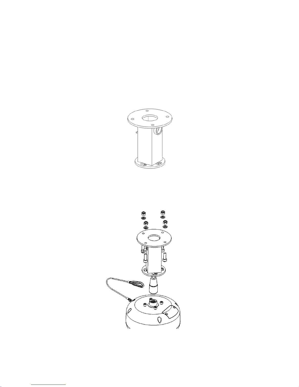
Each Camera unit is supplied with a 4” (101.6mm) PCD mounting adaptor to allow
mounting to industry standard brackets, tower and columns.
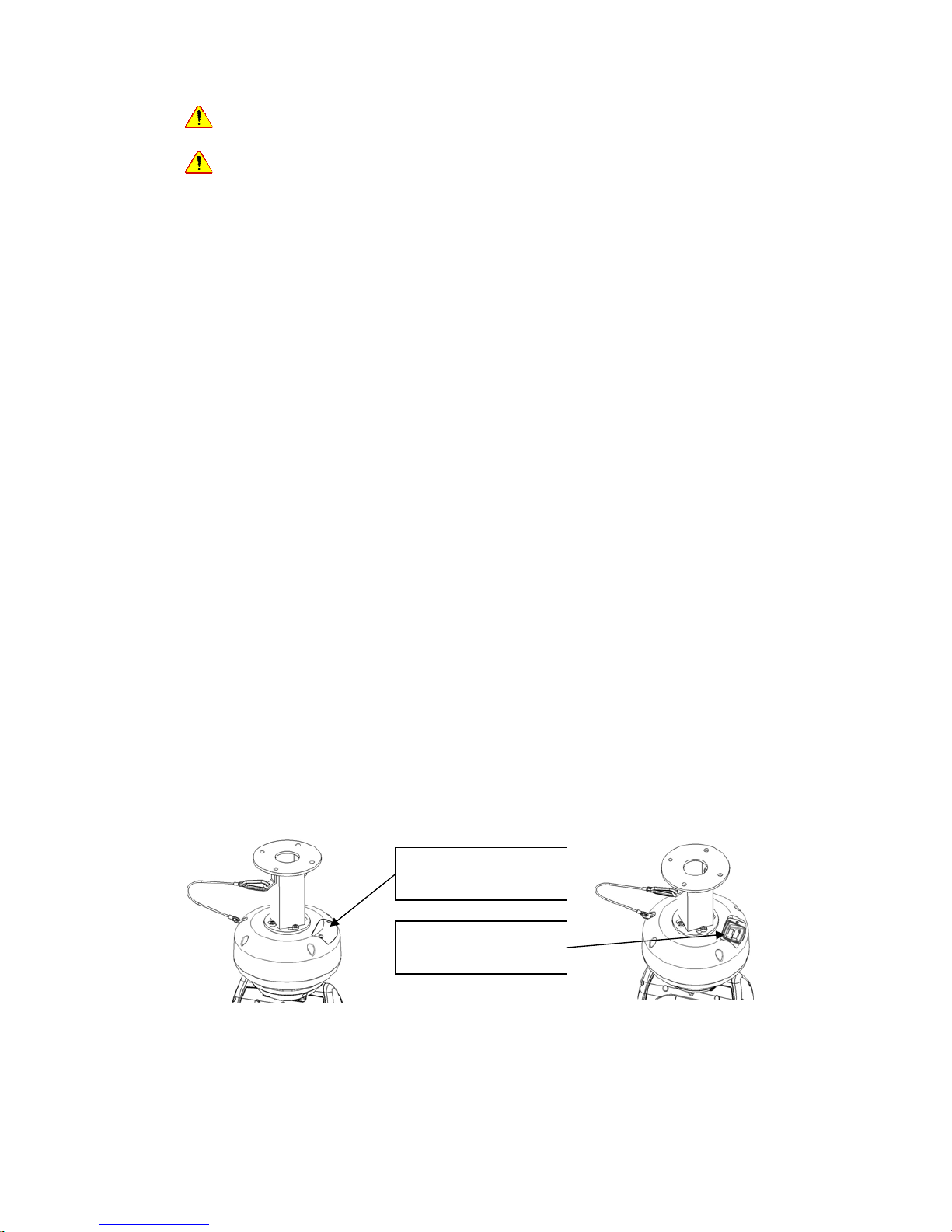
The adaptor as two cable entry points:
1. A pass-through hole in the plate to allow cabling through a column or tube
type mounting.
2. A M25 conduit thread in the side wall to permit flexible conduit to be
connected to the adaptor.
Figure 1
This adaptor should have the composite cable threaded through it before it is
mounted to the column or bracket. The cable should be dressed such that approx
25~35mm of the weatherproof connector is protruding out of the smaller plate that
connects to the Camera unit.
Figure 2
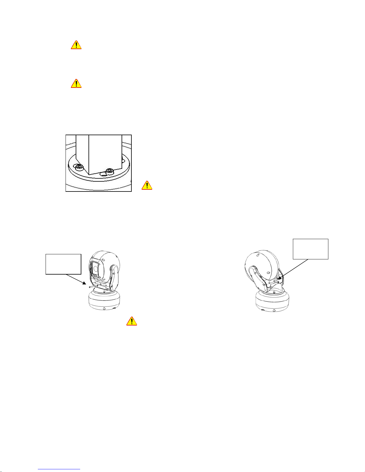
The 4” (101.6mm) PCD plate should then be mounted to bracket or tower using M8
bolts, washers and Ny-Loc type nuts.
6
It is important that this type of nut is used to prevent injury should the bolts
work loose in operation, due to vibration.
A stainless steel wire lanyard and clip is provided as a safety measure should any of
the bolts that hold the body of the Camera unit to the adaptor bracket work loose.
Always use the lanyard to support the Camera unit during installation and
ensure that it is connected and in use when the Camera unit mounting is
complete.
Insert the connector into the socket on the Camera unit, and screw home the
retaining ring.
Push the connector back into the adaptor bracket and align
the allen head bolts with the keyhole slots.
Push the heads through the keyholes and turn the Camera
unit body so that the bolt heads drop into their respective
receptacles. The bolts should then be tightened to approx
1.6Kg/m.
Do not over tighten bolts
Figure 3
Offset Mounting
When mounting upright, an offset can be added to allow the camera field of view to
clear the pan motor section of the housing.
Unscrew and withdraw the M5
socket head retaining bolt
from the middle of the front of
the yoke.
Tip the tilt housing and yoke
assembly forward.
Re-insert the bolt from the rear
and screw home. The Torque
figure is approx 0.97Kg/m
Do not over tighten the bolt
Power Supply
The Camera unit can accept a wide range of power supply input voltages.
The applicable range is 20-36Vdc or 14-26Vac. It draws 15W peak and 5W when idle.
This however does not take account of any optional heating of cooling devices in the Camera
unit, nor optional IR lighting systems.
The RCPS1 Camera unit power supply is capable of providing sufficient current to run the
Camera unit and a 24VAC washer pump (Typical example Dennard WW5 or WW25).
This supply also has built-in transient suppression and individually fused outputs for the
Camera and Washer units, as well as spark-gap protection for video and data connections.
Each output fuse has positive indication of failure, so a blown fuse is instantly identified.
The RCPS1 pcb layout is shown below in Figure 4.
The pcb has a number of connector strips for terminations in and out of the camera plus
power output terminals and a ground lug.
Retaining
bolt
Retaining
bolt

7
Camera unit Composite Cable ~ RCPS1 connections
Connections for the Camera unit Composite cable should be made to the terminals
as follows:
URM70 Video:
Connect the centre core to the terminal marked “VIDEO”
Connect the screen to the terminal marked “GND”
Power:
Connect the Red 20AWG cable to the terminal marked PTZ 1P
Connect the Black 20AWG cable to the terminal marked PTZ 1N
Washer:
Connect one White 20AWG cable to the upper terminal marked AUX1
Connect the other White 20AWG cable to the upper terminal marked AUX2
RS485 data:
Connect the Yellow 26AWG cable to the upper terminal marked DATA 5
Connect the Blue 26AWG cable to the upper terminal marked DATA 6
Earth:
Connect the Green/Yellow cable to the Earth stud adjacent to the BNC
output socket.
The IR Lamp and Ethernet terminals are reserved for future use.
CE- RCPS1 1.0
P3
P2
P1
SLOT
2P
1P
AC IN
ON
12
3
45
6
56432
1
VIDEO OUT
24V AC IN
PTZ
WASHER
1P 1N 2P 2N
MANUFACTURED IN THE E.U.
F0
F1
L1
L2
LL1
MOV1
CHOKE
7446720047
L0
R0
F2
R1
R2
R3
R4
CN0
PUMP
WASHER FEED
WASHER OUTPUT
IR LAMP +
IR LAMP -
RS485 +
RS485 -
TXD +
TXD -
RXD +
RXD -
GREEN
WHITE/
GREEN
WHITE/
ORANGE
ORANGE
ETHERNET
DATA
POWER
AUX
AUX
POWER
DATA
ETHERNET
7
8
910
789
10
V
GND
I
D
E
O
Figure 4
RCPS1 System Side Connections
Video:
The Video output from the RCPS1 and Camera unit is available on the pcb
mounted BNC socket. Connect the coaxial cable back to the monitor / matrix
or DVR to this socket. If the Camera unit and control system are configured to
use coax based telemetry, it will pass through this connector.
Data:
Connect RS485A (RS485+) to the lower terminal marked DATA 5
Connect RS485B (RS485-) to the lower terminal marked DATA 6
Power:
Connect 240VAC Live the to the mains input marked L
Connect 240VAC Neutral the to the mains input marked N
Connect 240VAC Earth the to the mains input marked E
8
The supplier installed mains input cable to the RCPS1 should have an isolator
fitted and be fused according to its gauge and local electrical regulations.
Failure to observe such regulations may result in injury or death
Telemetry Control
The Camera unit is designed to be added to any telemetry controlled system by
providing compatibility to a number of industry standard control protocols. This can
be done by directly using the on-board protocols or by adding a third party protocol
converter to interface between an incompatible control protocol and one of the onboard protocols.
Telemetry control is by RS485 or Co-axial video telemetry.
Due to the limitations or software changes of the some of the protocols, it is not
always possible to implement all of the features of the Camera unit with the Original
Manufacturers protocol, thus some features on a manufacturers keyboard, may limit
the way the Camera unit can operate.
Using RS485 based telemetry camera addresses are limited to 127 addresses.
On-Board Protocols
The Camera unit has the following on board protocols:
American Dynamics / Sensormatic RS422 (uni-directional only)
BBV Coaxial Telemetry
CBC C-Dome RS485
DeView [VTC]
Kalatel DP
Overview RS485
Pelco Co-Axitron
Pelco D 2400 baud
Pelco P 4800 baud
Pelco P 9600baud
DIL Switches
All addressing and protocol selection is set by 2 banks of 8way DIL switches located
on the main body of the housing, underneath a removable weatherproof cover.
Cover retained by
two screws
Screws and cover
removed

9
Figure 5
Protocol Settings
The Protocol selection is made on Switches S1-8, S2-1, S2-2, S2-3 and S2-7
The protocol selection is defined by the following table.
Coax based protocols do not use the RS485 address, so this can be left in the
Address 0 state.
Description Protocol No. S1-8 S2-1 S2-2 S2-3 S2-7
Dennard/ Overview RS485 0 Off Off Off Off Off
Pelco P 9600 1
On
Off Off Off Off
Pelco P 4800 2 Off
On
Off Off Off
Kalatel DP 5
On
Off
On
Off Off
Sensormatic RS422 6 Off
On On
Off Off
VTC / DeView RS485 9
On
Off Off
On
Off
Pelco D 2400 10 Off
On
Off
On
Off
CBC C-dome RS485 12
Off Off
On On
Off
Pelco Coaxitron 24 Off Off Off
On On
BBV coax 31
On On On On On
Figure 6
RS485 Address Settings
RS485 address settings are set by S1-1 to S1-7 and provide binary addresses to a
camera id of 127.
S2-8 is for termination of the RS485 bus. Set to ON to enable termination at the
camera.
The camera addressing is defined as below (a “-“ indicates switch in OFF position):
Address S1-1 S1-2 S1-3 S1-4 S1-5 S1-6 S1-7 Address S1-1 S1-2 S1-3 S1-4 S1-5 S1-6 S1-7
0 - - - - - - - 64 - - - - - - ON
1 ON - - - - - - 65 ON - - - - - ON
2 - ON - - - - - 66 - ON - - - - ON
3 ON ON - - - - - 67 ON ON - - - - ON
4 - - ON - - - - 68 - - ON - - - ON
5 ON - ON - - - - 69 ON - ON - - - ON
Camera
ID number
switches
Controller
protocol
switches
RS485
Termination

10
6 - ON ON - - - - 70 - ON ON - - - ON
7 ON ON ON - - - - 71 ON ON ON - - - ON
8 - - - ON - - - 72 - - - ON - - ON
9 ON - - ON - - - 73 ON - - ON - - ON
10 - ON - ON - - - 74 - ON - ON - - ON
11 ON ON - ON - - - 75 ON ON - ON - - ON
12 - - ON ON - - - 76 - - ON ON - - ON
13 ON - ON ON - - - 77 ON - ON ON - - ON
14 - ON ON ON - - - 78 - ON ON ON - - ON
15 ON ON ON ON - - - 79 ON ON ON ON - - ON
16 - - - - ON - - 80 - - - - ON - ON
17 ON - - - ON - - 81 ON - - - ON - ON
18 - ON - - ON - - 82 - ON - - ON - ON
19 ON ON - - ON - - 83 ON ON - - ON - ON
20 - - ON - ON - - 84 - - ON - ON - ON
21 ON - ON - ON - - 85 ON - ON - ON - ON
22 - ON ON - ON - - 86 - ON ON - ON - ON
23 ON ON ON - ON - - 87 ON ON ON - ON - ON
24 - - - ON ON - - 88 - - - ON ON - ON
25 ON - - ON ON - - 89 ON - - ON ON - ON
26 - ON - ON ON - - 90 - ON - ON ON - ON
27 ON ON - ON ON - - 91 ON ON - ON ON - ON
28 - - ON ON ON - - 92 - - ON ON ON - ON
29 ON - ON ON ON - - 93 ON - ON ON ON - ON
30 - ON ON ON ON - - 94 - ON ON ON ON - ON
31 ON ON ON ON ON - - 95 ON ON ON ON ON - ON
32 - - - - - ON - 96 - - - - - ON ON
33 ON - - - - ON - 97 ON - - - - ON ON
34 - ON - - - ON - 98 - ON - - - ON ON
35 ON ON - - - ON - 99 ON ON - - - ON ON
36 - - ON - - ON - 100 - - ON - - ON ON
37 ON - ON - - ON - 101 ON - ON - - ON ON
38 - ON ON - - ON - 102 - ON ON - - ON ON
39 ON ON ON - - ON - 103 ON ON ON - - ON ON
40 - - - ON - ON - 104 - - - ON - ON ON
41 ON - - ON - ON - 105 ON - - ON - ON ON
42 - ON - ON - ON - 106 - ON - ON - ON ON
43 ON ON - ON - ON - 107 ON ON - ON - ON ON
44 - - ON ON - ON - 108 - - ON ON - ON ON
45 ON - ON ON - ON - 109 ON - ON ON - ON ON
46 - ON ON ON - ON - 110 - ON ON ON - ON ON
47 ON ON ON ON - ON - 111 ON ON ON ON - ON ON
48 - - - - ON ON - 112 - - - - ON ON ON
49 ON - - - ON ON - 113 ON - - - ON ON ON
50 - ON - - ON ON - 114 - ON - - ON ON ON
51 ON ON - - ON ON - 115 ON ON - - ON ON ON
52 - - ON - ON ON - 116 - - ON - ON ON ON
53 ON - ON - ON ON - 117 ON - ON - ON ON ON
54 - ON ON - ON ON - 118 - ON ON - ON ON ON
55 ON ON ON - ON ON - 119 ON ON ON - ON ON ON
56 - - - ON ON ON - 120 - - - ON ON ON ON
57 ON - - ON ON ON - 121 ON - - ON ON ON ON

11
58 - ON - ON ON ON - 122 - ON - ON ON ON ON
59 ON ON - ON ON ON - 123 ON ON - ON ON ON ON
60 - - ON ON ON ON - 124 - - ON ON ON ON ON
61 ON - ON ON ON ON - 125 ON - ON ON ON ON ON
62 - ON ON ON ON ON - 126 - ON ON ON ON ON ON
63 ON ON ON ON ON ON - 127 ON ON ON ON ON ON ON
Figure 7
RS485 Termination
If the Camera unit is installed using a RS485 based control system, care needs to
taken to ensure the RS485 bus is terminated properly to prevent erratic operation.
The maximum length of cable that be used on one cable section in 1.2Km. There is a
maximum number of 32 devices that can reside on a cable section. All devices must
be un-terminated, with the exception of the last unit which must have its RS485
termination set to
ON (S2-8 ON)
CAT5 cable or any cable that meets or exceeds the requirements for EIA RS485 may
be used for RS485 telemetry control
Figure 11
Keyboard Operation
Where possible, manufacturer key sequences have been implemented to make the
control of the camera unit as close as possible to the “normal” telemetry system
implemented by the OEM manufacturer, i.e. presets and tours can be programmed
and recalled in the same way from the manufacturers control system.
Where it has not been possible to implement all of the Camera unit features with a
manufacturer’s protocol, the extra features can be accessed through the camera unit
on-screen-menu.
Note – OE manufacturers may update software or protocols in their keyboards
without prior warning, This may change the way in which the Camera unit behaves in
relation to keyboard operation. The manufacturer accepts no responsibility for such
changes in OE Manufacturer software/protocols.
-

12
On Screen Menu Access
Using the following sequences, the Camera unit OSD menu can be accessed. The
MENU sequence will open the OSD and the SELECT sequence will accept the
current data displayed.
Overview
Menu: Recall Preset 94
Select: Recall Preset 1
Pelco (All types)
Menu: Store preset 95
Select: Iris Open or Recall Preset 1
DeView
Menu: ENT (to open) / ESC (to exit)
Select: ENT
CBC C-Dome (RS485)
Menu: Recall Preset 95
Select: Recall Preset 1
American Dynamics / Sensormatic RS422
Menu: Recall / Store Preset 94
Select: Recall Preset 0
Kalatel
Menu: Recall / Store preset 64 or Menu
Select: Recall Preset 0
BBV TX400 (Coax)
Menu: Shift (or #) + 1
Select: Recall Preset 1
BBV TX1000
Menu: Shift + Wash
Select: Recall Preset 1
BBV TX1500
Menu: 1 then #
Select: Recall Preset 1
Dedicated Micros DS/BX range:
Menu: * 8 8 9 10 10 2 or ** (depending on S/W version)
Select: Recall Preset 1

13
Menu Structure
Camera On-Screen-Display
Opening screen
Start up screen
Selecting RUN from the MAIN MENU allows a user to go to a pre-set
position or start a tour. There are 32 pre-set positions, 8 slow tours (S), 8
fast tours (F) and 4 one-minute mimic (M) tours. When a programmed
position or tour is selected the menu will be cleared from the screen and
the unit will execute the appropriate function.
In this guide the yellow
border indicates the
item is flashing
This arrow confirms
the item selection and
returns the user to the
appropriate menu
Selecting the arrow will
take the user to the
previous screen
This arrow deletes the
last item selected by
the user

14
Run Menu Screen
RUN menu screen
If a position or tour is not set a message will be displayed, POSITION NOT SET
or TOUR NOT SET, respectively. WASH moves the unit to the wash position, if it
has been set, and starts the screen wash process. WIPE activates the wiper for 5
seconds.
Setup Screen
Start up screen
The SETUP menu gives the operator full access to set up presets and
tours as well as other features of the unit. SETUP menu is password
protected
 Loading...