


EIS Box™
Instrument
Operator’s Manual
Copyright © 2018 Gamry Instruments, Inc.
Revision 1.0
November 1, 2018
Gamry P/N 988-00071

2

3
If You Have Problems
Please visit our service and support page at www.gamry.com/service-support/. This page contains information
on installation, software updates, and training. It also contains links to the latest available documentation. If you
are unable to locate the information you need from our website, you can contact us via email using the link
provided on our website. Alternatively, you can contact us one of the following ways:
Internet www.gamry.com/service-support/
Telephone (215) 682-9330 9:00 AM–5:00 PM, US Eastern Standard Time
(877) 367-4267, Toll Free US and Canada Only
Please have your instrument model and serial numbers available, as well as any applicable software and
firmware revisions.
If you have problems in installation or use of a system containing an EIS Box, please try to call from a phone
next to your computer, where you can type and read the screen while talking to us.
We will be happy to provide a reasonable level of free support for registered users of the EIS Box instrument.
Reasonable support includes telephone assistance covering the normal installation, use, and simple
customization of a computerized system containing an EIS Box instrument connected to a Windows®compatible computer.
A service contract that extends both the hardware warranty and software update period is available at an
additional charge. Software updates do not include software enhancements offered to our customers at
additional cost.
Enhancements to the EIS Box instrument and Gamry’s standard applications software that require significant
engineering time on our part can be performed on a contract basis. Contact us with your requirements.

4
Limited Warranty
Gamry Instruments, Inc. warrants to the original user of this product that it shall be free of defects resulting from
faulty manufacture of the product or its components for a period of two years from the original shipment date
of your purchase.
Gamry Instruments, Inc. makes no warranties regarding either the satisfactory performance of the EIS Box
instrument including the software provided with this product or the fitness of the product for any particular
purpose. The remedy for breach of this Limited Warranty shall be limited solely to repair or replacement, as
determined by Gamry Instruments, Inc., and shall not include other damages.
Gamry Instruments, Inc. reserves the right to make revisions to the system at any time without incurring any
obligation to install same on systems previously purchased. All system specifications are subject to change
without notice.
There are no warranties which extend beyond the description herein. This warranty is in lieu of, and
excludes any and all other warranties or representations, expressed, implied or statutory, including
merchantability and fitness, as well as any and all other obligations or liabilities of Gamry Instruments,
Inc., including but not limited to, special or consequential damages.
This Limited Warranty gives you specific legal rights and you may have others, which vary from state to state.
Some states do not allow for the exclusion of incidental or consequential damages.
No person, firm or corporation is authorized to assume for Gamry Instruments, Inc., any additional obligation or
liability not expressly provided herein except in writing duly executed by an officer of Gamry Instruments, Inc.

5
Disclaimers
Gamry Instruments, Inc. cannot guarantee that the EIS Box instrument will work with all computer systems,
operating systems, and third-party software applications, hardware, or software.
The information in this manual has been carefully checked and is believed to be accurate as of the time of
release. However, Gamry Instruments, Inc. assumes no responsibility for errors that might appear.
Copyrights
EIS Box Instrument Operator’s Manual copyright © 2018, Gamry Instruments, Inc., all rights reserved.
Gamry Framework copyright © 1989–2018, Gamry Instruments, Inc., all rights reserved.
EIS Box, Reference 600, Framework, and Gamry are trademarks of Gamry Instruments, Inc.
No part of this document may be copied or reproduced in any form without the prior written consent of Gamry
Instruments, Inc.
Windows and Excel are registered trademarks of Microsoft Corporation.

6

7
Table of Contents
Chapter 1:Safety Considerations ..................................................................................................... 9
Inspection ......................................................................................................................... 9
Product Safety .................................................................................................................. 9
Grounding in the EIS Box .................................................................................................. 9
Temperature and Ventilation ............................................................................................. 11
Defects and Abnormal Stresses .......................................................................................... 11
Environmental Limits......................................................................................................... 12
Cleaning ........................................................................................................................... 12
Service ............................................................................................................................. 12
RF Warning ...................................................................................................................... 13
Electrical Transient Sensitivity ............................................................................................ 13
CE Compliance ................................................................................................................. 13
RoHS Compliance ............................................................................................................ 13
Chapter 2:Introduction .................................................................................................................. 15
About this Manual ............................................................................................................ 15
About the EIS Box ............................................................................................................. 15
Software and Applications ................................................................................................. 16
Notational Conventions..................................................................................................... 16
Chapter 3:General Operation ........................................................................................................ 17
Operation Overview ......................................................................................................... 18
Keyword Definitions ......................................................................................................... 19
Switching and Inactive Cell Control ................................................................................... 19
Communications Overview ............................................................................................... 19
Chapter 4:Installation ..................................................................................................................... 21
Initial Visual Inspection ..................................................................................................... 21
Physical Location .............................................................................................................. 21
Computer Requirements ................................................................................................... 22
Quick-Start Guide for System Installation........................................................................... 22
Software Installation .......................................................................................................... 22
Reboot Your Computer after Software Installation .............................................................. 23
Power Cord and Power Connection .................................................................................. 23
Power-up Test .................................................................................................................. 24
Ethernet Cables ................................................................................................................. 24
Operation via USB ............................................................................................................ 25
Cell Cable Installation ....................................................................................................... 25
Running the Framework .................................................................................................... 26
Framework Device Status Bar ............................................................................................ 26
Firmware Update .............................................................................................................. 27
Chapter 5:Calibration .................................................................................................................... 29
Introduction ...................................................................................................................... 29
DC Calibration .................................................................................................................. 29
Chapter 6:Cell Connections ........................................................................................................... 31
Cell Cable Overview ......................................................................................................... 31
Normal Cell Connections .................................................................................................. 31
Membrane Cell Connections ............................................................................................. 32
Fuses in the Cell Cable ...................................................................................................... 33
Chapter 7:Panel Indicators and Connectors .................................................................................... 37
Front Panel ....................................................................................................................... 37
Rear Panel ........................................................................................................................ 39

8
Appendix A: EIS Box Specifications ................................................................................................ 43
Control Amplifier .............................................................................................................. 43
Differential Electrometer ................................................................................................... 43
Voltage Measurement ....................................................................................................... 43
Current to Voltage Converter ............................................................................................. 44
Current Measurement ....................................................................................................... 44
Environmental ................................................................................................................... 44
General ............................................................................................................................ 44
Channel Characteristics ..................................................................................................... 45
Appendix B: EIS Box Cell Connectors ............................................................................................. 47
Appendix C: CE Certificate ............................................................................................................. 49
Certificate of Conformance ............................................................................................................ 49
Index ............................................................................................................................................. 51
Safety Considerations
9
Chapter 1: Safety Considerations
Your EIS Box instrument has been supplied in a safe condition. This chapter of the EIS Box Instrument
Operator’s Manual contains information and warnings that you must follow to ensure continued safe operation
of the EIS Box.
Inspection
When you receive your EIS Box instrument, inspect it for evidence of shipping damage. If you observe any
damage, please notify Gamry Instruments Inc. and the shipping carrier immediately. Save the shipping
container for possible inspection by the carrier.
Product Safety
The EIS Box has been designed, tested, and certified to meet the requirements of EN 61010, Safety
requirements for electrical equipment for measurement, control, and laboratory use. As defined in this standard,
it is a Category II apparatus, with any “hazardous live voltages” protected by “reinforced insulation”.
Most of the EIS Box circuitry operates at voltages low enough to be considered safe. The EIS Box contains a
limited amount of internal circuitry that is at “hazardous live” voltage as defined in EN 61010 (the standard
mentioned above). “Reinforced insulation” (again defined in EN 61010) is used to reduce the risk of electrical
shock caused by this hazardous live voltage.
The majority of the EIS Box’s circuitry does not contain voltages higher than 15 V DC. Generally input and
output voltages in the EIS Box are limited to ±9 V. This voltage level is considered safe.
The EIS Box is normally provided with an AC line cord suitable for your location. This AC line cord connects the
AC mains to the chassis of the instrument. You must always use a line cord with a CEE 22 Standard V female
connector on the instrument end of the cable. If your EIS Box has been provided without an AC line cord, or a
cord that is not compatible with your local AC mains socket, obtain a line cord certified for use in your country.
Contact your local Gamry Representative or email to techsupport@gamry.com if you are uncertain what AC
line cord to use.
Grounding in the EIS Box
Protective Ground and System Ground Binding Posts
The Protective Ground binding post is a convenient access point to the protective (earth) ground in the EIS
Box. It is connected to the third wire in the AC power cord and to the EIS Box’s metal chassis.
This binding post can be connected to an additional earth ground to form a redundant protective ground.
The EIS Box’s power input is rated for operation from 100 to 240 V AC, 47 to 63 Hz. It
should therefore be useful throughout the world.
Warning: An EIS Box damaged in shipment can be a safety hazard. Do not operate
damaged apparatus until a qualified service technician has verified its safety. Tag a damaged EIS Box to
indicate that it could be a safety hazard.

Safety Considerations
10
Most electrochemical cells are isolated from earth ground, so isolation of the EIS Box from earth is not required.
In these cases, connection of the EIS Box chassis to System Ground may lower the noise seen in an
electrochemical test.
The System Ground is the common voltage reference point for the EIS Box’s circuitry. It floats with respect to
the Protective Ground.
The System Ground binding post is not intended for any use other than connecting the EIS Box to an earth
ground to improve shielding against noise. Connecting this binding post to a hazardous voltage can create a
significant safety hazard.
The EIS Box contains surge suppressors that limit the voltage difference between the EIS Box’s chassis ground
and earth ground to about 28 V. These surge suppressors are not part of the safety mechanisms in the EIS Box.
Instead they are present to limit the possibility of improper instrument operation or instrument damage due to
electrostatic discharge (static electricity) and other surge events such as lightning.
Warning: Never connect the Protective Ground and System Ground if the
electrochemical system you are testing is earth-grounded. Two earth-ground connections in a high-energy
electrochemical system can create hazardous conditions.
Warning: Do not connect the Protective Ground binding post to any voltage other than
earth ground. An improper connection can create a safety hazard, which could result in personal injury or
death.
Warning: Do not negate the protection of the EIS Box’s earth ground by any means. Do
not use the EIS Box with a two-wire extension cord, with an adapter that does not provide for protective
grounding, or with an electrical outlet that is not properly wired with a protective earth ground. If the
protective ground is not properly connected, it creates a safety hazard, which could result in personal injury
or death.
Sources of earth ground include
• Most metal water pipes,
• The chassis of most electronic apparatus (which are generally earth-grounded), and
• The protective ground terminal of an AC mains power plug.
We recommend that you discuss grounding with an electrical or electronics professional prior to making this
earth-ground connection.

Safety Considerations
11
Temperature and Ventilation
Your EIS Box instrument was designed for indoor use at ambient temperatures between 0C and 45C.
The EIS Box uses forced-air cooling to keep the EIS Box components within their operating temperature range.
Most of the air needed to cool the EIS Box enters the chassis through holes in its bottom plate.
The fan within the EIS Box has two operating speeds with different audible noise levels. The EIS Box normally
operates with the slower, quieter fan setting. The fan switches to a higher speed when the EIS Box’s internal
heat sink gets hotter than 50C.
The cooling air exits through the back of the instrument.
Be careful when operating the EIS Box in an enclosed space (such as an enclosed relay rack or NEMA
enclosure). The temperature within the enclosure must not exceed 45C. You may need to provide ventilation
holes or even forced air-cooling for the enclosed space if excessive temperature rise occurs.
Defects and Abnormal Stresses
Treat your EIS Box as potentially hazardous if any of the following is true of the unit:
• It shows visible damage,
• It does not operate properly,
• It has been stored for a long period of time under unfavorable conditions,
• It has been dropped or subjected to severe transport stress,
• It has been subjected to environmental stress (corrosive atmosphere, fire, etc.).
Do not use your EIS Box or any other apparatus if you think it could be hazardous. Have it checked by qualified
service personnel.
Caution: The surge suppressors can be irreparably damaged by non-transient voltages
that exceed their threshold voltage of ±28 V. In the worst case this can cause catastrophic failure of the
system. Do not connect an EIS Box to a cell in a battery or fuel cell stack when the cell voltage is more than
25 V from earth ground.
Caution: Do not block the airflow into or out of the EIS Box chassis. The circuitry is
thermally protected so over-temperature will cause the instrument to enter a shut-down state. If shut-down
occurs during data-acquisition, experimental data could be lost. Running the EIS Box without adequate
cooling could also shorten the time to failure of some of the circuitry.

Safety Considerations
12
Environmental Limits
Note that there are environmental limit conditions on the storage, shipping and operation of this equipment.
The EIS Box has not been designed for outdoor use.
Storage
Ambient temperature
–40C to 75C
Relative humidity
Maximum 90% non-condensing
Shipping
Same as storage plus
Acceleration
Maximum 30 G
Operation
Ambient temperature
0C to 45C
Relative humidity
Maximum 90% non-condensing
Cleaning
Clean the external chassis only when necessary.
Disconnect the EIS Box from all power sources prior to cleaning.
Use a cloth lightly dampened with either clean water or water containing a mild detergent, to clean the outside
of the EIS Box enclosure. Alternatively, you may use isopropyl alcohol. Do not use a wet rag or allow fluid to
enter the EIS Box enclosure. Do not immerse the EIS Box in any type of cleaning fluid (including water). Do not
use any abrasive cleaners.
Service
Except for switching between Ethernet and USB communications, your EIS Box instrument has no userserviceable parts inside. Refer all service to a qualified service technician.
Warning: Never operate the EIS Box with any cover or panel on the chassis open.
Dangerous voltages may be present at several points within the EIS Box chassis, including PC board traces.
Always remove the power connection before opening the EIS Box case.
Warning: The EIS Box is not designed for operation in conditions where liquid water may
enter the chassis, or water vapor may condense within the chassis. Operation of an EIS Box that has water
within the chassis can create a safety hazard, which could result in personal injury or death.

Safety Considerations
13
RF Warning
The EIS Box has been tested for both radiated and conducted RF interference and for immunity to RF fields,
and has been found to be in compliance with FCC Part 18 and EU Council Directive 2014/30/EU, the EMC
Directive EN 61326:2013—Electrical equipment for measurement, control, and laboratory use—EMC
Requirements. Testing was performed in accordance with the Basic Immunity Requirements contained in Table
1 and the Emission Requirements contained in Section 7.
However, your EIS Box instrument still does generate some radio-frequency energy. The radiated levels are low
enough that the EIS Box should not create an interference problem in most industrial laboratory environments.
Your EIS Box instrument may also respond to environmental radio-frequency energy. We recommend you
avoid using mobile phones and other radio-frequency equipment in the same room as an EIS Box. The EIS Box
circuitry has been tested for operation in high-intensity RF fields and has demonstrated little response to those
fields. However, there is no guarantee that the electrochemical cell and its connections will not respond to RF
fields. This response most often appears as DC shifts in a cell’s response caused by rectification of the RF signal.
A Faraday cage surrounding your cell may be used to minimize the effect of environmental RF fields. If your cell
is isolated from earth ground, Gamry recommends connecting the System Ground to a Faraday cage.
Electrical Transient Sensitivity
Your EIS Box instrument was designed to offer reasonable immunity from electrical transients, including
transients on the incoming AC mains supply and electrostatic discharge. It has been tested for compliance with
EN 61326-1:2013—Electrical equipment for measurement, control, and laboratory use—EMC Requirements
describing acceptable limits for electrical transient susceptibility in laboratory test equipment. It should continue
to operate when subject to the standard ESD and power-line events defined in EN 61326-1:2013.
In severe cases involving transients beyond the limits tested in EN 61326-1:2013, the EIS Box could still
malfunction as a result of electrical transients. If you are having problems in this regard, the following steps may
help:
If the problem is static electricity (sparks are apparent when you touch the EIS Box or its cables):
• Try placing your EIS Box on a static-control work surface. Static-control work surfaces are now generally
available from computer-supply houses and electronics-tool suppliers. An antistatic floor mat may also
help, particularly if a carpet is involved in generating the static electricity.
• Air-ionizers or even simple air-humidifiers can reduce the voltage available in static discharges.
If the problem is AC power-line transients (often from large electrical motors near the EIS Box):
• Try plugging your EIS Box into a different AC power branch circuit.
• Plug your EIS Box into a power-line surge-suppressor. Inexpensive surge-suppressors are now generally
available because of their use with computer equipment.
Contact Gamry Instruments, Inc. if these measures do not solve the problem.
CE Compliance
The European Community has instituted standards limiting radio-frequency interference emitted by electronic
devices, setting limits for susceptibility of apparatus to RF energy and transient events, and mandating safety
requirements. Gamry Instruments, Inc. has designed and tested the EIS Box to comply with these standards.
The relevant CE regulations include EN 61010-1:2010 and EN 61326-1:2013.
RoHS Compliance
The EIS Box is built using lead-free components and lead-free solder. It complies with the European RoHS
initiative.

Safety Considerations
14

Introduction
15
Chapter 2: Introduction
About this Manual
This manual covers the installation, safety, and use of the Gamry Instruments EIS Box instrument with Revision
7 (and later revisions) of the Gamry Framework software. It is equally useful when setting up a newly-purchased
instrument or modifying the setup of an older instrument for use with new software. Technical material such as
specifications and connector pin-outs is in the Appendices.
This manual discusses software installation and software operation in some detail. The installation is written
assuming installation using Revision 7 of Gamry’s Framework software. Installation is also described in Gamry
Instruments’s Quick-Start Installation Guide.
Software support for the EIS Box is described in the Gamry Help system.
All Gamry Instruments applications running under the Gamry Framework control the EIS Box via a PSTAT
object. See the Framework’s Help for information concerning PSTAT objects and their functions.
About the EIS Box
The EIS Box (pronounced “ice box”) is a value-oriented, research-grade electrochemical instrument packaged in
a small case. It is designed to for battery-testing via electrochemical impedance spectroscopy up to eight cells.
The EIS Box excels at electrochemical impedance testing of small- to medium-sized single-cell energy-storage
and power-conversion devices. Such devices include batteries, electrical double-layer capacitors, fuel cells, and
photovoltaic cells. The EIS Box can apply and measure currents from 5 A to ~0.05 µA.
Features of the EIS Box include:
• Six-decade current auto-ranging for large and small batteries,
• Electrical isolation from earth ground, and
• Both analog and digital filtering.
A sine-wave generator on the EIS Box allows the instrument to make accurate impedance measurements at
frequencies up to 100 kHz. EIS performance is good for low-impedance systems (such as low-ESR electrical
double-layer capacitors).
A unique DSP (Digital Signal Processing) data-acquisition mode allows the EIS Box to reject noise, from the
instrument itself, from the electrochemical cell, and from the lab environment. In many cases where other
instruments require a cell in a Faraday shield to make quiet measurements, the EIS Box can be used with the
cell exposed on a bench top.
The EIS Box, like all of our instruments, requires a computer for its use. The EIS Box connects to this computer
through an Ethernet or USB connection (see photograph below of rear panel).

Introduction
16
The EIS Box was developed to increase the throughput of your impedance testing program. Under the control
of an external computer, the EIS Box connects one cell at a time, which makes an electrochemical
measurement on that cell.
The EIS Box has been integrated into all Gamry Instruments’ electrochemical impedance spectroscopy
applications that run under the Gamry Framework. It allows many of the EIS measurement applications to
increase their throughput by testing multiple cells in a single test run.
The Gamry Instruments Electrochemical Toolkit allows you to control the EIS Box using a library of software
routines. You can find examples of such routines after you install the Electrochemical Toolkit software.
Software and Applications
The EIS Box supports Gamry Instruments’ electrochemical impedance spectroscopy software under the
Framework system.
Typical applications for the EIS Box include:
• Research in electrochemical storage and conversion, and
• Battery and electrochemical capacitor evaluation.
Notational Conventions
In order to make this manual more readable we have adopted some notational conventions. These are used
throughout this manual and all other Gamry Instruments manuals:
• Numbered lists. A numbered list is reserved for step-by-step procedures, with the steps always
performed sequentially.
• Bulleted list. The items in a bulleted list, such as this one, are grouped together because they represent
similar items. The order of items in the list is not critical.
• File names and folders. References to computer files and Windows
®
folders are shown in Courier font,
for example: C:\MYGAMRYDATA\CV.DTA and GAMRY.INI.

General Operation
17
Chapter 3: General Operation
The EIS Box was developed to increase the throughput of your electrochemical impedance testing program. It
allows one instrument to drive up to eight electrochemical cells. Under the control of an external computer, the
EIS Box connects one cell at a time to the instrument, which makes an electrochemical measurement on that
cell.
The EIS Box was specially designed for the needs of electrochemists. Extra features such as sense line and
shield-switching—designed specifically for electrochemists—from other general-purpose switching devices.
The EIS Box is integrated into all Gamry Instruments’ electrochemical impedance spectroscopy applications that
run under the Gamry Instruments Framework software. It allows many of the applications to increase their
throughput by testing multiple cells in a single test run.
This chapter of the EIS Box Operator’s Manual provides an overview of the operation of the EIS Box. It discusses
the following topics:
• Operation overview
• Switching and inactive cell control
• Communications overview
The material in this chapter is only an overview. If you are using your EIS Box with Gamry Instruments software
this overview should give you sufficient understanding to make intelligent use of your EIS Box.

General Operation
18
Operation Overview
Figure 3-1 shows a “typical” electrochemical test system built around an EIS Box instrument. Only four cells are
shown in this figure, although up to eight cells can be connected.
Figure 3-1
A Typical Electrochemical Test System Using the EIS Box
The system computer is a critical component of the system. It controls the EIS Box by sending it simple
commands through an ethernet or USB connection.
The most important function of these commands is to select which cell is active (connected to the EIS Box). You
can think of an EIS Box as a complex switch with driving electronics. One of the eight cell cables on the EIS Box
is switched so that it connects to the instrument’s cell cable. All of the wires (including sense leads and shields)
in the cell cable are switched.
Battery
(Inactive)

General Operation
19
The system computer also controls the instrument. When a cell is connected to the instrument cell leads, the
computer causes a test to be run on that cell. The test can be as simple as a single current or potential
measurement or as complex as a cyclic scan. The computer software and instrument are responsible for taking
the measurement and storing it.
The EIS Box instrument in Figure 3-1 is shown as a “black box”. The relays in the EIS Box can carry currents up
to 5 A.
In a typical EIS Box experiment, the system computer cycles through the cells. Each cell is connected in turn to
the instrument and used to collect a measurement. Usually the computer delays at the end of each cycle
through the cells so that the measurements on each cell are separated by a fixed time period.
Keyword Definitions
Active Cell
The active cell is the cell (if any) currently connected to the system potentiostat. Any electrochemical
measurements are made on the active cell.
Cell
The term cell is used to describe either an electrochemical cell or the switches needed to connect an
electrochemical cell to the instrument.
Channel
An EIS Box contains eight channels. A channel includes cell-switching relays. The term cell is used
when only the cell-switching portion of a channel is being discussed.
Inactive Cell
The term inactive cell is any cell not currently connected to the instrument.
Instrument
This is the instrument responsible for making electrochemical measurements on the cells used in the
experiment. The instrument is typically an EIS Box.
System Computer
The computer responsible for coordinating operation of an EIS Box-based electrochemical test system,
not to be confused with the very simple micro-controller buried within the EIS Box.
Switching and Inactive Cell Control
In the Operation Overview, we said you can think of the EIS Box as a complex switch with controller. Each of
the eight EIS Box channels is made up of an independent set of switches and control circuits. All the switches
are under control of the system computer. The system computer must insure that only one cell at a time is
connected to the instrument, therefore a main switch controls which cell is active.
Communications Overview
The system computer communicates with the EIS Box via an ethernet connection or a USB cable.
Switching from channel to channel involves electromechanical relays. You will hear a click
each time relays activate during the switching process.

20

Installation
21
Chapter 4: Installation
This chapter of the Gamry Instruments Inc. EIS Box Operator’s Manual covers normal installation of the EIS Box.
We assume the EIS Box is installed as part of a Gamry Instruments’ Framework-based electrochemical
measurement system containing a Microsoft Windows®-compatible computer.
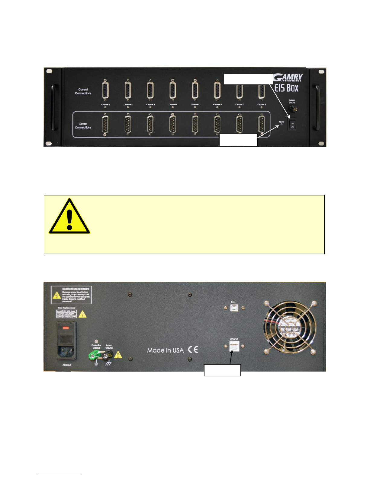
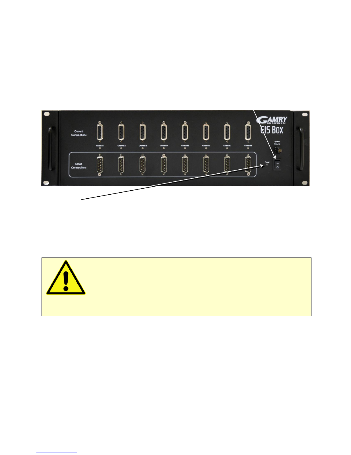
Figure 4-1
Front View of the EIS Box
Initial Visual Inspection
After you remove your EIS Box from its shipping carton, check it for any signs of shipping damage. If you
observe any damage, please notify Gamry Instruments, Inc. and the shipping carrier immediately. Save the
shipping container for possible inspection by the carrier.
Physical Location
Normally users place their EIS Box on a flat workbench surface. Keep easy access to the rear of the instrument
because some cable connections are made from the rear. The EIS Box is generally operated in a “flat” position
(see Figure 4-1). Operation in other orientations is possible as long as you insure that air movement through the
chassis is not restricted.
Warning: The “reinforced insulation” that keeps the operator from accessing the
“hazardous live” voltages in the EIS Box can be rendered ineffective if the EIS Box is damaged in shipment.
Do not operate damaged apparatus until a qualified service technician has verified its safety. Tag a damaged
EIS Box to indicate that it could be a safety hazard.
If the EIS Box is taken from a cold location (for example outdoors in winter conditions) to a warm, humid
location, water vapor may condense on the cold surfaces inside the EIS Box, possibly creating a hazardous
condition. Before connecting power to a “cold” EIS Box, allow at least one hour for the EIS Box to warm at
room temperature.

Installation
22
If you place your EIS Box within an enclosed space, make sure that the internal temperature within that space
does not exceed 45C, the maximum ambient temperature for the EIS Box. Be particularly careful if a computer
or other heat-dissipating equipment is mounted in the same enclosure as the EIS Box.
The EIS Box is not designed for outdoor use.
Computer Requirements
Before you connect an EIS Box to a computer, you must make sure that your computer meets these
requirements:
• A computer based on one of the x86 or x64 families of Intel microprocessors, or a 100%-
compatible processor from another vendor,
• Microsoft
®
Windows 7 or higher is required. Both 32-bit and 64-bit versions of these operating
systems are supported. See the Gamry website “www.gamry.com” if you have a newer edition of
Windows®.
• An ethernet port or a USB port.
Quick-Start Guide for System Installation
Your shipment should have included a document entitled Quick-Start Installation Guide. It contains the latest
instructions for installing Gamry Instruments’ hardware and software onto a computer system. If this document
is missing, you can find it on www.gamry.com. The Quick-start Guide found at www.gamry.com contains the
latest information concerning system installation, so the information provided below is always subject to
change.
Software Installation
The EIS Box is compatible with the Windows® Plug & Play configuration system. Like most Plug & Play
hardware, it is best if you install the software for the EIS Box before you install the instrument hardware.
Gamry Instruments’ software can be installed from a physical medium such as a DVD or a pre-programmed
software flash drive, or it can be installed via an Internet download. The most up-to-date download can be
found on www.gamry.com.
If you install from a physical medium, Gamry Software Setup program will normally start automatically when
you place the Gamry Instruments’ installation medium into your computer.
An Internet download of Gamry Instruments’ software will download a self-extracting .EXE file. Running this file
will extract the software and begin the same installation process as you get with a physical medium.
If you have inserted the Gamry DVD or flash drive into your computer and the Gamry Setup program does not
start automatically:
1) Navigate to the root folder of the device containing the Gamry Software (DVD or Flash Drive) or to a
Windows® folder containing the Gamry Software.
2) Run the program called AUTORUN.EXE found in this folder.
Caution: Do not block the airflow into or out of the EIS Box chassis. The EIS Box will
enter a power-down state if it becomes overheated. If this occurs during data-acquisition, you may lose
experimental data.
Installation
23
If you do not know how to navigate to the Gamry Installation device, consult your local computer expert or
network administrator, or email techsupport@gamry.com.
AUTORUN.EXE runs a set-up program. In most cases, you can choose the default choices or the most obvious
choices on all screens shown during the set-up process.
Reboot Your Computer after Software Installation
Reboot your computer when the Gamry Setup program is done. The Setup program normally offers you the
opportunity to do so. Following Setup, you may not be able to use your EIS Box until the drivers are loaded.
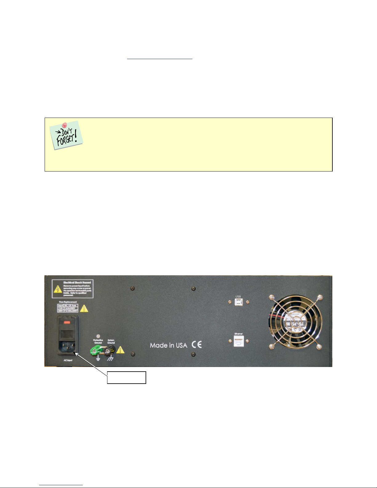
Power Cord and Power Connection
The mains are connected to the AC Input jack on the rear of the EIS Box (Fig. 4-2).
The power supply provided inside the EIS Box is rated for operation from 100 to 240 V AC, at frequencies from
47 to 63 Hz. It should therefore be useable worldwide.
The EIS Box is normally supplied with a line cord suitable for use in the United States. In other countries, you
may have to replace the line cord with one suitable for your type of mains (electrical outlet). You must always
use a line cord with a CEE 22 Standard V (IEC 320 C13) female connector on the end of the cable leading to
the unit. This is the same connector used on the US standard line cord supplied with your EIS Box.
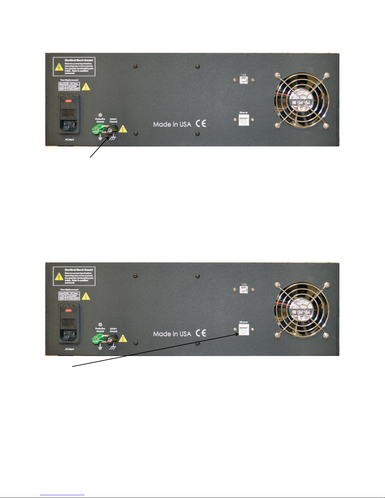
Figure 4-2
Rear Panel of the EIS Box
Device driver installation may not occur until a while after the Windows Desktop appears. On
a slow computer, or a busy computer with lots of active applications, the delay before driver installation can
be a minute or more.
AC Input
Installation
24
Power-up Test
Before you make any other connections to your EIS Box, check that the EIS Box is at least nominally functional.
After connecting AC power to the EIS Box, toggle the Power switch on the front panel of the EIS Box.
Watch the Power LED as the EIS Box powers up. It glows a steady blue. If you do not see a continuous blue
color, contact technical support.
The status of the other LED indicators is not important at this time.
Ethernet Cables
The EIS Box connects to the computer using a shielded CAT5E Ethernet cable (see figure below).
The Ethernet connection should not be “hot-plugged”. This means both the computer and the EIS Box must be
powered OFF before the ethernet cable is plugged in.
Caution: If the Power LED goes on, then turns off and stays off, the EIS Box is not
working properly! If this power-up test fails, contact Gamry Instruments or your local Gamry Instruments
representative as soon as possible.
Power LED
Power switch
Ethernet
Installation
25
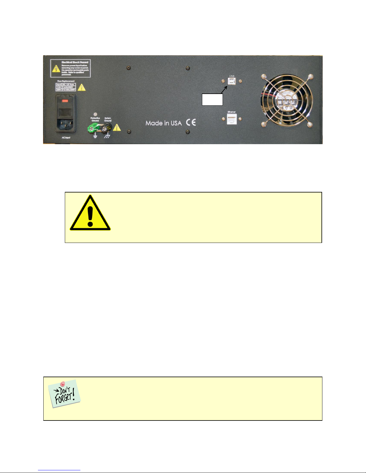
Operation via USB
The EIS Box can be run via USB. To connect the EIS Box to a USB port on a computer:
1. Be sure that the EIS Box is powered off and unplugged from the AC source (mains).
2. Unscrew the screws holding the top panel onto the chassis. Remove the top panel of the EIS Box
chassis.
3. Unplug the USB connection cable from the USB Type B (approximately square) port on the aluminum
assembly inside the EIS Box.
4. Uncoil the USB cable affixed to the inside of the rear panel, and connect it to the now-free USB Type
B port on the aluminum assembly.
5. Reattach the top panel on top of the EIS Box chassis.
6. Connect your computer to the external USB Type B port on the rear panel of the EIS Box (see image
above), using a USB cable.
Cell Cable Installation
The Cell Cables connect pairwise to two 15-pin D-type connectors located on the front of the EIS Box (see
Figure 4-1) for each channel. There are two cables per channel: one that carries the cell current, called the
Current Carrying Cable which mates with the Current Connector, and one that senses the cell voltage, called
the Sense Cable, which mates with the Sense Connector.
The standard Cell Cable is 3 m long. The D-connector ends of the cables are connected to the appropriate
ports on the front of the EIS Box. Always use the knurled screws on this cable to hold the cables in place.
Warning: Never remove the top panel of the EIS Box while the instrument is
powered on. The electrical currents inside the EIS Box can cause severe injury.
The current-carrying cable contains fuses that protect the instrument against excessive cell
current. See Chapter 6 for more information concerning these fuses.
USB

Installation
26
Running the Framework
Many newer electrochemical applications do not run as an application within Gamry Instruments’ Framework
software. This is true of all applications that use Gamry’s Toolkit for instrument control. Gamry’s Framework
software is the main application software for performing routine analysis associated for electrochemical
measurements. There are other software programs such as Resonator that are stand-alone programs. Programs
that you develop using our toolkits will fall into the stand-alone software category.
The Framework Instrument Manager is useful in organizing the instruments in the system. The Framework also
has a Calibration program that is used to calibrate instruments connected to the system.
Framework Device Status Bar
By default, the Gamry Framework shows a Device Status Bar under its main menu (see Figure 4-3). If you do
not see the Device Status Bar when you run the Gamry Framework, it has been disabled in the Framework
Options menu.
Instruments that are connected to the computer appear on this bar. The round indicator associated with each
device shows its status:
Green
The device is available to run experiments
Orange
The device is currently running an experiment
White
The device is connected to the system, but is not usable. This is generally the result of a mismatch
between the Framework software and the device’s firmware. You can use the Gamry Instrument
Manager to fix the mismatch.
The screen capture below shows a Framework screen with three USB instruments connected.
Figure 4-3
Framework with Three Potentiostats and One Running Test

Installation
27
The Interface 1000 (IFC 01004) in this system is shown with a green indicator because it is installed and ready
to run. The Reference 600 labeled My Ref600 has an orange indicator because it is recording the EIS spectrum
shown on the screen. The Reference 600 labeled Jims Ref600 has a white indicator, showing it is plugged in but
cannot be used. This is an indication of a version mismatch between Gamry Instruments Framework software
and the instrument’s firmware.
Firmware Update
Your EIS Box was shipped with the latest version of all its firmware. From time to time, Gamry Instruments
makes changes to the instrument’s firmware code and a firmware update is required to make use of the new or
improved code.
There are three separate firmware images that can be updated in the field on your EIS Box. The first is the
Instrument Firmware. This is the program that handles most of the functions of the EIS Box. The second is the
Communications Firmware. This program handles the communications between your EIS Box and the host
computer. The third is the PLD firmware, which you should only change if a Gamry Instruments representative
instructs you to.
Initiate the Firmware Update process using the Framework Options, Instrument Manager... command.
Appropriate update files can be obtained from the Gamry Instruments website at www.gamry.com. If you
encounter a problem updating the firmware in your EIS Box, please contact Gamry Instruments for assistance.
Caution: Interrupting a firmware update can cause a catastrophic failure of your system.
Do not turn off the EIS Box, do not unplug the communications cable, and do not stop the operation of
the host computer when the USB LED is a continuous red color.
Do not interrupt a firmware update that is in progress. An incomplete update can render an EIS Box
inoperable until it is returned to Gamry for reprogramming.
Should the firmware update be interrupted, contact Gamry before starting the return process.


Calibration
29
Chapter 5: Calibration
Introduction
DC calibration for the EIS Box instrument is sometimes necessary.
Run calibration through the Framework™ software, or directly through Gamry Instrument Manager (GIM).
Gamry recommends calibrating the instrument at least once per year, or when the quality of your data is in
question. To initiate calibration, take the following steps:
Click the Calibrate in Framework button, located in the Calibration area of GIM. This launches the appropriate
calibration routine for the instrument selected in GIM. Follow the instructions given in Framework. See the
relevant Calibration Quick Start Guide for additional details.
If there are any failures during calibration, click the Email Results to Gamry Support button in GIM. One of
our support engineers will review the results and provide appropriate advice.
You run the Instrument Manager by selecting Options/Instrument Manager... on the Framework Menu.
Calibrate each potentiostat installed in your system. A calibration utility is provided with the Gamry Framework.
The calibration for the EIS Box is divided into two sections: Instrument DC Calibration and cable calibration.
Gain access to these calibration procedures via the Utility selection on the Framework’s Experiment dropdown menu.
Calibrate each potentiostat installed in your system. A calibration utility is provided with the Gamry Framework.
Get access to the calibration procedure via the Utility selection on the Framework’s Experiment drop-down
menu.
DC Calibration
This procedure uses an external resistive dummy cell called the 200 Ω Calibration Cell.
Caution: The standard EIS Box calibration calls for an external resistive dummy cell.
Your EIS Box was shipped with a 200 Ω Calibration Cell, which includes a 200 Ω, 0.05% accurate resistor.
After calibration, please place this dummy cell in a safe place where you can find it if your unit requires
recalibration.
If you do need to recalibrate and you cannot find your calibration cell, you can perform DC Calibration
using a different 200 Ω resistor. Its power-rating is unimportant. Some performance checks in the
calibration process may fail if the resistors inaccuracy exceeds 0.2% (4 Ω).

Calibration
30
Potentiostat calibration is only required infrequently. Recalibrate your EIS Box under the following
circumstances:
• It is at least one year since your last calibration.
• Your instrument has been serviced.
• You notice breaks or discontinuities in the data curves recorded with your system.
• The system is being run in an environment that is very different from the previous operating environment.
For example, if the EIS Box was calibrated at 15°C and you are now operating it at 30°C, you should
recalibrate.
Connect the Calibration Cell to the appropriately colored banana plugs on the Cell Cable.

Cell Connections
31
Chapter 6: Cell Connections
Cell Cable Overview
The EIS Box has eight channels. Each channel has two Cell Connectors on the front of the EIS Box. The Current
Connections are female 15-pin D-connectors, and the Sense Connections are male 15-pin D-connectors.
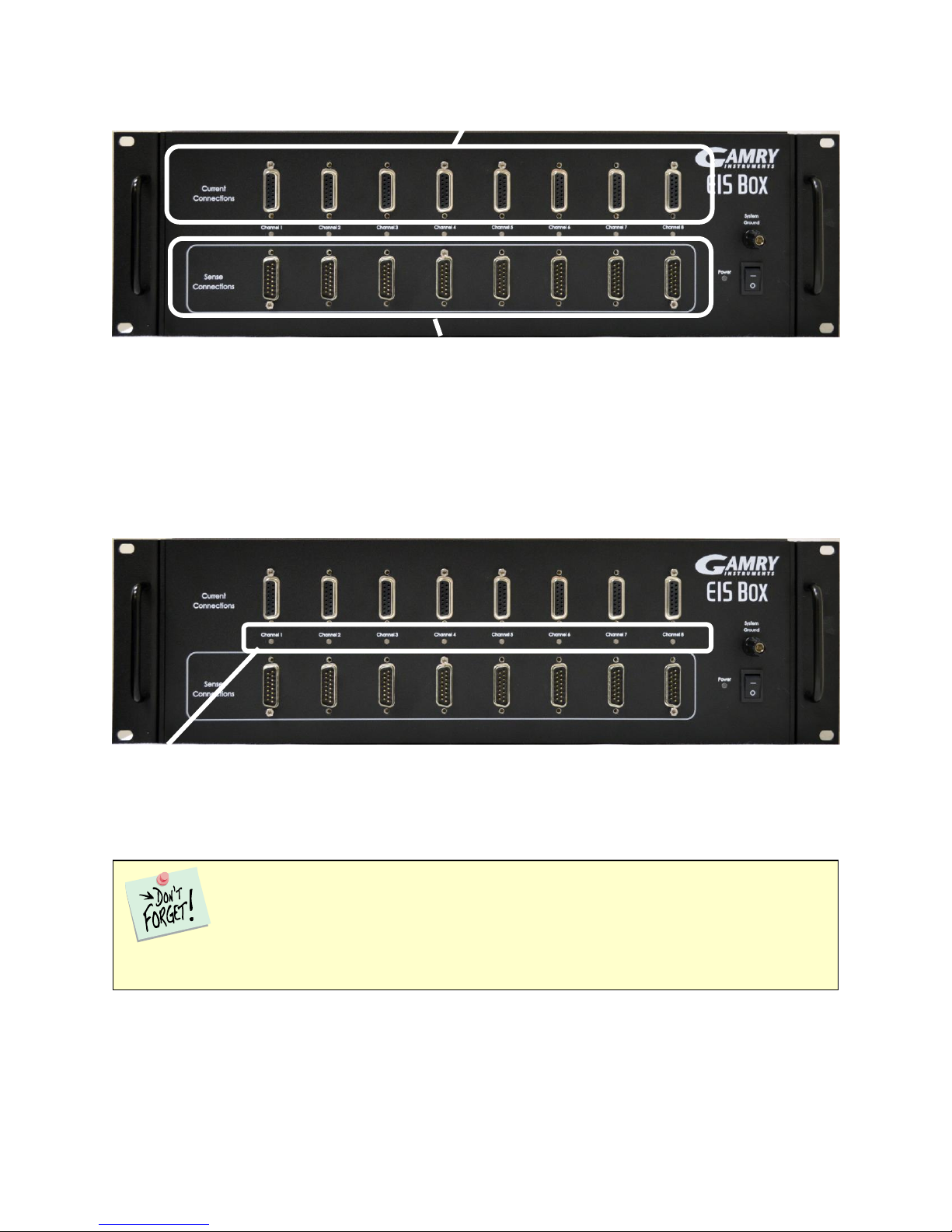
Figure 6-1
Front Panel of the EIS Box
The upper (female) connectors are labeled Current Connector. They carry the cell current between the
Counter electrode wires and the Working electrode wires.
The lower (male) connectors are labeled Sense Connector. They contain only high-impedance inputs used to
sense potentials in the cells.
Gamry’s EIS Box standard cell cables always come in pairs. Each cable has a D-connector on one end, and a
number of leads to connect to electrodes in an electrochemical cell. The D-connector end of the cable is
connected to the appropriate D-Connector on the front of the EIS Box. The male and female cables cannot be
interchanged.
Every EIS Box is shipped with eight pairs of standard shielded cell cables. The Gamry part number for the
Current Cable is 985-00183, and the Sense Cable is 985-00184. They are both 3 m complex cables, with
D-connectors on one end, and color-coded banana plugs on the other end.
Always screw both cell cables into place because cables can fall off the unit if not properly attached. This can be
disastrous if detachment occurs during an experiment.
Ancillary Apparatus
Do not use the EIS Box with ancillary apparatus connected directly to any of the cell leads. Examples of ancillary
apparatus include DVMs, oscilloscopes, chart-recorders, and data-loggers. Ammeters and voltmeters, regardless
of their specifications, almost always create problems when connected to the EIS Box cell leads.
Normal Cell Connections
This section assumes that you are using standard, shielded cell cables. This information does not depend on the
length of such cables.
The cell end of the standard cell cables terminates in a number of banana plugs and pin jacks. Each termination
comes with a removable alligator clip. Table 6-1 identifies the terminals of the cables.
Cell Connections
32
Table 6-1
Cell Cable Terminations
Color
Type
Name
Normal Connection
Blue
Banana Plug
Working Sense
Connect to working electrode
Green
Banana Plug
Working Electrode
Connect to working electrode
White
Banana Plug
Reference
Connect to counter electrode
Red
Banana Plug
Counter Electrode
Connect to counter electrode
Connect both the blue and green cell leads to the positive terminal (usually). The working electrode is the
electrode being tested. The blue plug connection senses the voltage of the working electrode. The green
working electrode connection carries the cell current. The working electrode may be as much as 520 mV above
the circuitry ground (floating ground).
Connect the white plug to the negative terminal (usually). The measured cell potential is the potential
difference between the blue and white cell connectors.
Connect the red banana plug to the negative terminal also. The counter-electrode terminal is the output of the
EIS Box’s power amplifier.
If your cell is a typical glass laboratory cell, all of the electrodes are isolated from earth ground. In this case, you
may be able to reduce noise in your data by connecting the EIS Box’s Floating Ground to an earth ground.
Membrane Cell Connections
The EIS Box can be used with membrane cells. In this type of cell, a membrane separates two electrolyte
solutions. Two reference electrodes are used: one in each electrolyte. Each electrolyte also contains a counter
electrode. The EIS Box controls the potential across the membrane. Table 6-2 shows the cell connections used
with a membrane type cell.
Caution: If any electrode in your cell is at earth ground, never connect the EIS Box
Protective Ground to System (floating) Ground. Autoclaves, stress apparatus, and field measurements may
involve earth-grounded electrodes. water pipe can be a suitable earth ground.
Warning: Make sure that your earth-ground connection is made to a legitimate source
of earth ground. Consult a qualified electrician if you are uncertain how to obtain an earth ground.
Connecting the EIS Box to an incorrect and unsafe voltage can create a safety hazard (see Chapter 1 for
details).
Cell Connections
33
Table 6-2
Cell Cable Connections for a Membrane Cell
Color
Type
Name
Normal Connection
Blue
Banana Plug
Working Sense
Connect to reference electrode #1
Green
Banana Plug
Working Electrode
Connect to counter electrode #1
White
Banana Plug
Reference
Connect to reference electrode #2
Red
Banana Plug
Counter Electrode
Connect to counter electrode #2
Fuses in the Cell Cable
The EIS Box can be damaged if currents much larger than 6 A flow into or out of the Counter electrode or
Working electrode leads. Improper connection to a battery, fuel cell, or supercapacitor can cause this type of
damaging current to flow.
All standard EIS Box Counter/Working cell cables include fuses in the current-carrying leads. These fuses protect
the instrument from the extremely large currents that can flow through an improperly connected
electrochemical-energy generation or storage device (including batteries, fuel cells, and capacitors). For
convenience, the term “battery” is used here to refer to all single-cell or stacked electrochemical devices that
can distribute energy.
Grounding errors on a battery can be particularly dangerous, for they can result in the battery being shorted
through the instrument.
Both the counter electrode lead and the working electrode lead have fuses, rated to carry 6.3 A.
Access to the fuses requires removal of two screws on opposite sides of the hood covering the D-connector end
of the Counter/Working cable. A drawing of the D-connector end of a cable with the hood opened is given in
Figure 6-3. The small rectangular fuses snap into fuse-holders labeled Work and Cntr. To remove the fuse,
Warning: The fuses in the EIS Box Counter/Working cell cable do not protect against a
safety hazard. They are needed to prevent damage to the instrument if it is improperly connected.
Reference electrode #1 and counter electrode #1 must be on one side of the membrane,
and reference electrode #2 and counter electrode #2 must be on the other side.
Always turn off the EIS Box and disconnect both ends of the Counter/Working cable before
checking or replacing the fuses in the cable.
Cell Connections
34
either grip it with small pliers and gently lift the fuse out of the fuse-holder, or pry the fuse out of the fuseholder using a small screwdriver or knife blade.
After a fuse has been removed, check it using an ohmmeter, such as that found on modern digital voltmeters.
Do not trust a visual inspection of the fuse. A blown (open) fuse always should have a resistance of greater than
100 Ω. The resistance of a good fuse is very small.
Figure 6-3
Drawing of Fuse-holder in the D-Connector Hood
Four replacement fuses should accompany every Counter/Working cell cable shipped by Gamry Instruments.
The Gamry Part Number for the small rectangular fuses is 630-00030. If you need to find replacement fuses
locally, we currently only recommend Very Fast Acting, 6.3 A, Nano Fuses from the Littelfuse corporation
(Littelfuse part number 045106.3MRL). Fuses with similar ratings from other manufacturers have not been
tested, so we cannot recommend their use.
Don’t forget the jackscrews when you reassemble the hood.
Cell Connections
35
Testing for Open Fuses
A Gamry Instruments Framework test checks for blown fuses without having you remove the fuses. A simple
Potentiostatic test is run on the Calibration Cell. Run the test using the SET A VOLTAGE.EXP script in the
Framework’s Utilities package.
Connect the cell leads to the Calibration Cell. You do not need to place the Calibration Cell within a Faraday
cage. Select the command Experiment > Utilities > Set a Voltage on the Framework software’s menu bar.
You see a Set a Voltage dialog box similar to this:
Figure 6-4
Setup Dialog Box for the Set a Voltage Script
In the Voltage field, enter a Voltage of 1 V as shown above, then click the OK button. The Framework opens a
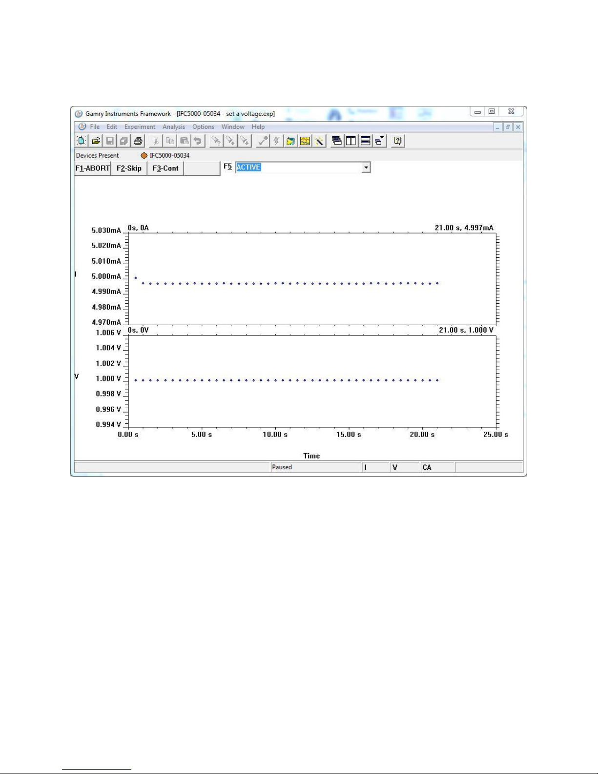
runner window, and a graph of current versus time should appear:
Caution: Always replace the fuses in an EIS Box cable with the recommended fuse. Use
of an improper fuse, especially a fuse with a higher current rating, can cause instrument failure if a battery
cell is improperly connected. Use of a non-approved fuse voids Gamry Instruments’ factory warranty.
Cell Connections
36
Figure 6-5
Typical Runner Window with Good Fuses
We expect you to see one of two very different results:
• If the instrument is working properly and the fuses in the cable are good, the measured current is ~5
mA as seen above. No overloads are seen.
• If the one or both fuses are open, all the current readings are near zero, and a red CA Overload
indication may be seen at the bottom of the runner window.
If this test indicates an open fuse, use the procedures described above to check both fuses. This test cannot tell
which fuse is blown. Both fuses can blow simultaneously.
If the fuse test indicates an open fuse, and the fuses both check out a good with an ohmmeter, some other
problem has occurred in the cables or the instrument. Contact Technical Support at Gamry Instruments as soon
as possible.
Panel Indicators and Connectors
37
Chapter 7: Panel Indicators and Connectors
Front Panel
Power Switch
The Power switch is on the far right side of the EIS Box Front Panel. Normally the blue Power LED illuminates
when the EIS Box is powered on; see the Power LED description below.
Power Switch
The Power LED
The Power LED is on the lower right of the EIS Box front panel. It normally glows a continuous blue when the
EIS Box is turned on and has passed some simple power-on tests.
When the Power LED is off, these are possible causes:
• The Power switch is off.
• There is no AC (mains) supply connected to the rear panel Power In connector.
• One of the internal DC power supplies has failed.
Cell Connectors
The EIS Box has two sets of eight cell cable connectors, for a total of 16 connectors on the front panel. Each
connector is a 15-pin D-type connector. Each pair of D-type connectors is a channel, for connection to a cell or
battery.
The upper (female) connectors are labeled Current Connector. They carry the cell current between the
Counter electrode wire and the Working electrode wires.
Caution: The Power LED indicates power status, and that power-up tests have passed.
Never rely on the Power LED as a true power-status indicator. Always unplug the Power In connection if
you suspect your EIS Box is malfunctioning.
Panel Indicators and Connectors
38
Current Connectors
Sense Connectors
The lower (male) connectors are labeled Sense Connector. They contain only high-impedance inputs used to
sense potentials in the cell.
In addition to the pins used for cell connections, each EIS Box Cell Connector also uses four pins to read a cell
cable ID. Gamry software can compensate for the cell-cable characteristics to attain optimal system
performance in EIS (Electrochemical Impedance Spectroscopy).
The cell connections are discussed in Chapter 3. A pin-out description of the cell cable connector is found in
Appendix B.
Channel LED
A Channel LED is between each pair of Cell connectors.
The Channel LEDs glow amber whenever the EIS Box is actively applying voltage or current to the
electrochemical cell attached to that channel. Avoid touching the cell cable leads whenever the Channel LED is
lit, because the quality of the data being collected in your experiment may be compromised.
If you need to make changes to your cell leads, do so after powering down the EIS Box.
In a typical experimental sequence, the Channel LED is off between experiments and during any open-circuit
potential measurements. It glows amber whenever that channel’s cell is polarized.
The Channel LED does not indicate a dangerous condition when it is lighted. The voltages
generated by the EIS Box are generally considered safe. Still, avoid touching the cell leads when the cell is
on.

Panel Indicators and Connectors
39
System Ground binding post
The front-panel System Ground black banana jack is intended for one use only. When the EIS Box is used with
cells isolated from earth ground, connecting the System Ground to earth ground may lower the noise measured
in the system. Note that the chassis of the EIS Box is isolated from the System (floating) Ground. Safety
information concerning this is in Chapter 1.
A banana plug is the only way you can connect to the Chassis Ground jack. Use a wire to connect the banana
plug to earth ground.
A black banana-plug-to-banana-plug lead is provided with your EIS Box. You may find it useful when making
this earth-ground connection.
Rear Panel
AC Input
The AC Input receptacle accepts a three-terminal AC line cord. You must always use a line cord with a CEE 22
Standard V female connector on the instrument end of the cable. The EIS Box derives all its power from your
local AC (mains). The input current is less than 2.1 A.
The AC Input jack is rated for operation from 100 to 240 V AC, at frequencies from 47 to 63 Hz. It should
therefore be useable worldwide.
Panel Indicators and Connectors
40
System Ground
The rear-panel System Ground black banana jack is intended for one use only. When the EIS Box is used with
cells isolated from earth ground, connecting the System Ground to earth ground may lower the noise measured
in the system. Note that the chassis of the EIS Box is connected to the Protective (earth) Ground. Safety
information concerning this is in Chapter 1.
Use a metal link to connect the Protective Ground to the System Ground as shown above.
Protective Ground
The green Protective Ground binding post is a convenient access point to the protective (earth) ground in the
EIS Box. It is connected to the third wire in the AC power cord and to the EIS Box’s metal chassis. This binding
post can be connected to an additional earth ground to form a redundant protective ground.
A black banana-plug-to-banana-plug lead is provided with your EIS Box. You may find it useful when making
the earth-ground connection (if a redundant protective ground is required).
Ethernet
The Ethernet port on the rear panel of the EIS Box is a receptacle for an RJ-45 ethernet cable. Use a standard
ethernet cable with RJ-45 connector to connect this port to a computer’s ethernet.
A suitable ethernet cable was included with your EIS Box. If this cable is lost, you can replace it with a cable
from your local computer retailer.

Panel Indicators and Connectors
41
USB
The USB port on the rear panel of the EIS Box is a Type B receptacle for a USB cable. Use a standard USB cable
with a Type B USB (nearly square) connector to connect this port to a computer’s USB port.
AC Power-line Fuses
This section gives step-by-step instructions for changing the AC power-line fuses in your EIS Box. Please follow
these instructions carefully. You need a small flat-blade screwdriver to perform this procedure.
1. Unplug the AC power line cord from the back of the EIS Box. The fuses cannot be changed with the AC
line cord plugged into the EIS Box.
2. Find the AC input module on the left side of the EIS Box’s rear panel. It can be identified by the line-cord
connector built into it.
3. Find the small slot on the right side of the AC input module near the line-voltage setting window. Place the
blade of a small screwdriver in this slot and pry open the AC input module.
4. The fuses are contained inside two fuse holders. The tops of the fuse holders are black plastic with a white
arrow on them.
Use the screwdriver to gently pry up the plastic portion of the fuse holders. After the fuse holders are up
about 1 cm you should be able to grab them with your fingers and pull them completely out of the AC
input module.
5. Remove the old fuses by prying them out of the fuse holders. Replace them with the correct fuses, which
simply pop into the fuse holders. The fuse orientation in the fuse holder is unimportant.

Panel Indicators and Connectors
42
Replace the fuse(s) only with the correct value and type of fuse. See Table 1-3 and the text preceding it for
fuse values and type descriptions.
6. Replace the fuse holders (with the correct fuses) in the AC input module. The arrows on the fuse holders
must point towards the bottom of the EIS Box.
7. Close the cover of the AC input module. It should snap into place.
8. Make sure you have not inadvertently changed the AC line-voltage setting, which is displayed in a small
window on the AC input module. If the voltage shown is not the appropriate setting for the line voltage in
your area, change it before powering up your EIS Box.
Caution: The AC line fuses are important components for safe operation of the EIS Box.
Do not replace the fuses with incorrect values or types, or in any way circumvent the fuse action. If
your EIS Box routinely blows the AC line fuses it indicates a serious problem with the EIS Box. Contact
Gamry Instruments, Inc. for repair information.

Appendix A: EIS Box Specifications
43
Appendix A: EIS Box Specifications
All specifications are at an ambient temperature of 22C, with the EIS Box powered using the external power
supply shipped with the unit, a standard shielded 3 m cell cables, and the cell enclosed in a Faraday shield. All
specifications obtain after software calibration.
A numbered note qualifies many of the specifications. Many of these notes describe the method used to
measure a specification. The notes are found at the end of this appendix.
All specifications are subject to change without notice.
Control Amplifier
Compliance Voltage
Min
6.5
V
Note 1
Output Current
Min
5
A
Note 2
Unity Gain Bandwidth
Typ
1050, 250, 43, 4.4, 0.5
kHz
Note 3
Slew Rate
Typ
10, 4.4, 0.7, 0.07, 0.007
V/µs
Note 4
Differential Electrometer
Max Input Voltage
Max
6.0
V
Note 4
Input Current
Max
25
pA
Note 6
Input Resistance
Differential (between inputs)
Common Mode (input to ground)
Typ
10
1
TΩ
Note 7
Input Capacitance
Differential (between inputs)
Common Mode (input to ground)
Typ
8
12
pF
Note 7
Bandwidth (–3 dB)
Min
12
MHz
Note 8
CMRR
DC to 10 kHz
10 kHz to 100 kHz
Min
98
88
dB
Note 9
Voltage Measurement
A/D Full Scale Ranges
Typ
6.5536
V
Notes 5, 10
Resolution (before gains)
Typ
200
µV/bit
Zero Offset Error
Max
0.5
mV
Note 11
Gain Error
Max
0.2 % Note 11
Offset Range
Typ
6.5536
V
Note 12
Post-offset Gain
Typ
1×, 10×, 100×

Appendix A: EIS Box Specifications
44
Current to Voltage Converter
Maximum Full-scale Range
±5 A Note 13
Minimum Full-scale Range
±50
±500 (after 100× gain)
µA
nA
Note 13
Voltage across Rm
Typ
±100
mV at
full scale
Note 14
Output Voltage (at Monitor and ADC in)
Typ
±3.0
V
full scale
Input Offset Current
Max
25
pA
Note 15
Range Zero Offset
Max
0.05
% of
range
Note 15
Gain Tolerance, 5 A to 50 µA
ranges
Max
0.2 % of
reading
Note 15
Zero drift
Typ
0.02
% FS/C
Note 16
Bandwidth (-3 dB)
Typ
5
MHz
Note 17
Current Measurement
Resolution
Typ
0.00333…
% FS/bit
Offset Range
Typ
±100
% of
range
Post-offset Gain
Typ
1×, 10×, 100×
Accuracy
Typ
Dominated by current-to-voltage error
(see above)
Environmental
Operating Temperature Range
0 to +45
°C Relative Humidity
Max
90 (non-condensing)
% Storage and Shipping Temperature
–25 to +75
°C Maximum Shipping Acceleration
30 g
General
DC Power Input Voltage
Range
100–240
V
Fuses
IEC 127
For 115 VAC, use 6.3 A 250 V
For 230 VAC, use 3.153 A 250 V
Power
Max
120 W
Leakage Current (floating, earthed
working electrode)
Typ
±10
nA
Note 22
Dimensions
41.5 W × 45.7 D × 13.3 H
cm
Mounting
Fits 19” (48.3 cm) standard rack mount
3 U height
Weight
Max
10
kg

Appendix A: EIS Box Specifications
45
Channel Characteristics
Mode
Active
Channel switching time
<10 ms
Cell current
5 A
Maximum carried
Counter electrode voltage
6.5 V
maximum
Measured versus EIS Box chassis ground.
Channel Isolation
Current leakage
<2 nA maximum
To active channel pin from any source.
Impedance
>500 MΩ
<20 pF
Equiv. impedance to EIS Box chassis ground.
NOTES:
1. Measured in galvanostatic mode with a high-power 2.4 load resistor connected from the counter to the
working electrode leads. The compliance voltage is measured using an external voltmeter across the 2.4
load. Under these conditions, the output current is approximately 2.72 A.
2. Measured with a high-power 1 load resistor connected between the counter and working electrode
leads, in potentiostatic mode.
3. Unity gain bandwidth and slew rate are correlated. Each has five settings, with the highest slew rate
occurring at the highest bandwidth, down to the lowest slew rate occurring at lowest bandwidth. Both are
measured with 2 k between counter and reference, and 20 between the reference and the working
and working sense leads.
4. Cell resistor 90 Ω connected between the counter and working electrode leads, in potentiostatic mode.
5. The A/D and signal-processing chain in the EIS Box allows measurement of voltage signals as large as
±6.5536 V. The voltage on the Work Sense lead can be as high as ±0.51 V when measuring 5A using a 60
cm cell cable. This implies a maximum voltage input on the differential electrometer of ±6.04 V.
6. This specification is tested using a 2 G resistor switched into the input and measuring the voltage
difference with and without the input resistance.
7. The differential impedance is measured between the Reference and Work Sense inputs. This is the
impedance you measure when you record the EIS spectrum of an infinite impedance (open lead) cell.
There is also a common-mode resistance and capacitance associated with the differential electrometer
inputs. These values tell you how much the electrometer response is modified by a resistance in series with
the source.
8. The bandwidth is for a sine-wave source with a 50 Ω output impedance driving either input. The
bandwidth is well in excess of this specification, which is limited by the measurement equipment used in
routine testing of the EIS Box.
9. CMRR is common-mode rejection ratio. It specifies the ability of the differential electrometer to reject
signals connected to both inputs. The CMRR is measured driving both inputs with a sine-wave source with
a 50 Ω output impedance, and measuring the error as a function of frequency. Resistance in either input
will cause a loss of CMRR.
10. Voltage measurement is performed with a nominal 6 V signal input to the ADC signal chain. The actual
full scale is 6.5536 V.
11. The total error in a voltage measurement is:
Error = Zero Offset Error + Gain Error × Voltage
For a 1 V signal the theoretical error can be as high as 2.5 mV. This error is typically less than 0.2 mV.
12. Offsets are summed into the signal. Offset inaccuracy is approximately ±0.05% of the setting plus ±0.5
mV.
13. There are six hardware current ranges, separated in sensitivity by decades. The ranges are 50 µ A, 500 µA,
5 mA, 50 mA, 500 mA and 5 A full scale. The ×10 and ×100 gains add two virtual ranges of 5 A and 500
nA full scale.

Appendix A: EIS Box Specifications
46
14. The voltage across the current measurement resistor, R
m
, is as shown. On ranges below 5 mA, the working
electrode voltage is similar to the voltage across Rm. At 5 A and 1 MHz, the working electrode voltage can
be as high as 0.51 V, because the cable has both resistive and inductive impedance.
15. The total error in a current measurement is:
Error = Input Current Offset + Range Zero Offset × FS Current + Gain Tolerance × Measured Current
The first term can generally be ignored on the EIS Box. The units for the error are amperes.
16. Drift can be approximated by simple drift in the Range Zero Error. In reality all three terms in the equation
above can have drift.
17. The Current to Voltage converter bandwidth is a function of the current range, the cell cable, and the
IEStability setting. Longer cell cables add capacitance and slow the current measurement.
The specified I/E Converter BW is measured at 5 mA I/E Range.
18. The total error in a voltage setting is:
Error = DC Zero Offset + Gain × Voltage Setting
For a 1 V signal the theoretical error can be as high as 2.5 mV. In practice the error is generally less than 1
mV.
19. This specification is guaranteed by design. It is not tested.
20. This specification is measured by applying zero voltage across a 1 Ω resistor and measuring current noise
on the 500 µA scale. 1 µV of voltage noise creates a current of 1 µA. The filters in the ADC Chain for the I
Signal are used to limit the bandwidths as shown in the specifications. Signal averaging via Gamry DSP
mode further reduces the measured noise.
21. Excluding external power adapter and any cables supplied with unit.
22. Isolation quality has both DC and AC factors, predominantly at the power-supply frequency of 300 kHz.
Only the DC leakage current is shown here. Measured under the following conditions: cell is a 10 kΩ
resistor, PSTAT mode, CA speed is normal, I/E stability is slow, I/E range is 50 µA, I-channel filter is 5 Hz,
and I-channel gain is 100.

Appendix B: EIS Box Cell Connectors
47
Appendix B: EIS Box Cell Connectors
Chapter 4 describes the connections between a cell cable and an electrochemical cell. This appendix describes
the other end of the cell cable.
Multiple pins assigned to the same signal are connected together on the EIS Box’s Potentiostat board. If you
must connect this using a special cell cable, you need a wire connected to any one of the D-connector pins.
Table B-1
Current Connector
Pin(s)
Signal Name
Use
1,9
Working
Connected to the working electrode (see Chapter 4).
2, 10
Working
Shield
The shield for the working electrode. Connected to Floating Ground on Dend of the cable. Left open at the cell end of the cell cable.
3
Ground
4, 11
Ground
The potentiostat’s floating ground. Can be used to shield the cell if very low
currents need to be measured. Also used as a shield for the counter electrode
cable.
5,12
Counter
Connected to the counter electrode
6
No
connection
7 CBL_ID1
One of four cable ID bits. Used to identify the type of cell cable attached to
the unit. Pull to a logic High through a resistor. Ground to set the bit low.
8
CBL_ID2
One of four cable ID bits. Used to identify the type of cell cable attached to
the unit. Pull to a logic High through a resistor. Ground to set the bit low.
13
Counter
shield
14
CBL_ID0
One of four cable ID bits. Used to identify the type of cell cable attached to
the unit. Pull to a logic High through a resistor. Ground to set the bit low.
15
CBL_ID3
One of four cable ID bits. Used to identify the type of cell cable attached to
the unit. Pull to a logic High through a resistor. Ground to set the bit low.

Appendix B: EIS Box Cell Connectors
48
Table B-2
Sense Connector
Pin(s)
Signal Name
Use
1
CBL_ID2
One of four cable ID bits. Used to identify the type of cell cable attached to
the unit. Pull to a logic High through a resistor. Ground to set the bit low.
2
CBL_ID1
One of four cable ID bits. Used to identify the type of cell cable attached to
the unit. Pull to a logic High through a resistor. Ground to set the bit low.
3
Ground
The potentiostat’s floating ground. Can be used to shield the cell if very low
currents need to be measured. Also used as a shield for the counter electrode
cable.
4
No
connection
5,6,12,14
Reference
Shield
The shield for the reference electrode input. Driven to the same potential as
Pin 13. Left open at the cell end of the cell cable.
7,15
Work Sense
Shield
The shield for the work sense electrode input. Driven to the same potential
as Pin 8. Left open at the end of the cell cable.
8
Work Sense
Connected to the working electrode in most cases (see Chapter 5). This lead
has a 261 Ω resistor in the cell end of the cable. Custom cell cables are likely
to require a similar resistor.
9
CBL_ID3
One of four cable ID bits. Used to identify the type of cell cable attached to
the unit. Pull to a logic High through a resistor. Ground to set the bit low.
10
CBL_ID0
One of four cable ID bits. Used to identify the type of cell cable attached to
the unit. Pull to a logic High through a resistor. Ground to set the bit low.
11
No
connection
13
Reference
Electrode
Connected to the reference electrode in most cases (see Chapter 4). This lead
has a 261 Ω resistor in the cell end of the cable. Custom cell cables are likely
to require a similar resistor.

Appendix C: CE Certificate--
49
Appendix C: CE Certificate
Certificate of Conformance

--
50

--
51
Index
AC line cord ................................................... 10
active cell ................................................. 20, 21
air-cooling ...................................................... 12
auxiliary electrode .......................................... 34
blue cell lead .................................................. 34
Calibrate in Framework button ...................... 31
calibration ................................................ 31, 32
Calibration Cell ........................................ 31, 37
CE Certificate ................................................. 51
CE Compliance ............................................... 14
cell
definition ................................................. 21
cell cables ...................................................... 33
cell connectors ............................................... 33
channel
definition ................................................. 21
Channel LED ................................................. 40
Chassis Ground .............................................. 41
cleaning ......................................................... 13
communications ............................................. 21
computer .... 3, 5, 14, 17, 18, 19, 21, 23, 24, 25,
26, 28, 29, 42, 43
computer requirements .................................. 24
contract engineering ......................................... 3
conventions
notational ................................................ 18
Counter electrode ........................ 33, 35, 39, 49
Current Carrying Cable ................................... 27
Current Connector ............................ 33, 39, 40
DC calibration ................................................ 31
Device Status Bar ........................................... 28
double insulation ............................................ 10
earth ground .................... 11, 14, 17, 34, 41, 42
electrical transients ......................................... 14
electrochemical impedance spectroscopy . 17, 18,
19, 40
enclosed space ............................................... 12
environmental limits ....................................... 13
environmental stress ....................................... 12
ethernet ..................... 13, 17, 20, 21, 24, 26, 42
Experiment drop-down menu ........................ 31
fan speed ....................................................... 12
firmware update ............................................. 29
Floating Ground binding post .............. 11, 41, 42
Framework™ software ........................ 17, 28, 31
fuses ...................................... 35, 36, 37, 38, 43
Gamry Framework .......................................... 17
Gamry Instrument Manager ...................... 28, 31
green cell lead ................................................ 34
ground ..................................................... 49, 50
Help system ................................................... 17
inactive
definition ................................................. 21
inspection ...................................................... 10
installation ...................................................... 23
Interface™ potentiostat ................................... 27
membrane cell connections ............................ 34
operation ....................................................... 13
Options menu ............................................... 28
Pin out ........................................................... 49
potentiostat ........................................ 19, 20, 21
Power Connection .......................................... 25
Power Cord .................................................... 25
Power LED ............................................... 26, 39
power line transient ........................................ 14
Power switch ............................................ 26, 39
power-up test ................................................. 26
radio frequency .............................................. 14
red cell lead ................................................... 34
Reference Electrode ........................................ 50
RF interference ............................................... 14
RoHS Compliance .......................................... 14
safety ............................................................. 10
Sense Cable ................................................... 27
Sense Connector ............................... 33, 40, 50
service............................................................ 13
service contract ................................................ 3
shielding against noise .................................... 11
shipping damage ...................................... 10, 23
software calibration ........................................ 45
software installation .................................. 24, 25
specifications .................................................. 45
static electricity ............................................... 14
storage ........................................................... 13
support ............................................................ 3
system computer ............................................ 20
definition ................................................. 21
System Ground ........................................ 41, 42
system potentiostat ......................................... 21
telephone assistance ......................................... 3
temperature ................................................... 12
Type B USB .............................................. 27, 43
Universal Dummy Cell.............................. 34, 37
USB port ................................ 13, 21, 27, 28, 43
Visual Inspection ............................................ 23
Warranty .......................................................... 4

--
52
Work Shield ................................................... 49 Working electrode ................. 33, 34, 35, 39, 49
 Loading...