

TDC5™ Temperature Controller
Operator’s Manual
Copyright © 2019 Gamry Instruments, Inc. All rights reserved. Printed in the USA.
Revision 1
January 21, 2019
Part # 988-00072
i

ii

1
Limited Warranty
Gamry Instruments, Inc. warrants to the original user of this product that it shall be free of defects resulting
from faulty manufacture of the product or its components for a period of two years from the date of
shipment.
Gamry Instruments, Inc. makes no warranties regarding either the satisfactory performance of the TDC5
Temperature Controller including the software used with this product or the fitness of TDC5-based systems
for any particular purpose. The remedy for breach of this Limited Warranty shall be limited solely to repair
or by replacement, as determined by Gamry Instruments, Inc., and shall not include other damages.
Gamry Instruments, Inc. reserves the right to make revisions to the TDC5 at any time without incurring any
obligation to install same on TDC5s previously purchased. All system specifications are subject to change
without notice.
There are no warranties which extend beyond the description herein. This warranty is in lieu of, and
excludes any and all other warranties or representations, expressed, implied or statutory, including
merchantability and fitness, as well as any and all other obligations or liabilities of Gamry
Instruments, Inc., including but not limited to, special or consequential damages.
This limited warranty gives you specific legal rights and you may have others which vary from state to state.
Some states do not allow for the exclusion of incidental or consequential damages.
No person, firm or corporation is authorized to assume for Gamry Instruments, Inc. any additional
obligation or liability not expressly provided herein except in writing duly executed by an officer of Gamry
Instruments, Inc.

2
If You Have Problems
Contact us at your earliest convenience. We can be contacted via:
Telephone (215) 682-9330 9:00 AM–5:00 PM US Eastern Standard Time
(877) 367-4267 Toll-free US & Canada Only
Fax (215) 682-9331
E-mail techsupport@gamry.com
Mail Gamry Instruments, Inc.
734 Louis Drive
Warminster, PA 18974
USA
If you write to us about a problem, provide as much information as possible.
If you are having problems in installation or use of this TDC5 Temperature Controller, please call from a
telephone next to the instrument, where you can change instrument settings while talking to us.
We are happy to provide a reasonable level of free support for TDC5 purchasers. Reasonable support
includes telephone assistance covering the normal installation, use, and simple tuning of the TDC5.

3
Disclaimers
Gamry Instruments, Inc. cannot guarantee that the TDC5 will work with all computer systems, heaters,
cooling devices, or cells.
The information in this manual has been carefully checked and is believed to be accurate as of the time of
printing. However, Gamry Instruments, Inc. assumes no responsibility for errors that might appear.
Copyrights and Trademarks
Gamry Framework™ Software Copyright © 1989–2019 Gamry Instruments, Inc.
CPT Software Copyright © 1992–2019 Gamry Instruments, Inc.
Explain Computer Language Copyright © 1989–2019 Gamry Instruments, Inc.
Gamry, Explain, Gamry Framework, CPT, and TDC5 are trademarks of Gamry Instruments, Inc.
Windows and Excel® are registered trademarks of Microsoft Corporation. OMEGA® is a registered
trademark of OMEGA ENGINEERING, INC.
No part of this document may be copied or reproduced in any form without the prior written consent of
Gamry Instruments, Inc.

4

5
Table of Contents
Limited Warranty ........................................................................................................................... 1
If You Have Problems .................................................................................................................... 2
Disclaimers .................................................................................................................................... 3
Copyrights and Trademarks ............................................................................................................ 3
Chapter 1: Safety Considerations .................................................................................................... 7
Introduction ...................................................................................................................... 7
Inspection ......................................................................................................................... 7
Line Voltages .................................................................................................................... 8
Switched AC Outlet Fuses ................................................................................................. 8
TDC5 Electrical Outlet Safety ............................................................................................ 8
Heater Safety .................................................................................................................... 9
RFI Warning...................................................................................................................... 9
Electrical Transient Sensitivity ............................................................................................ 9
Chapter 2: Installation ................................................................................................................... 11
Initial Visual Inspection ..................................................................................................... 11
Unpacking Your TDC5 ...................................................................................................... 11
Physical Location .............................................................................................................. 11
Differences Between an Omega CS8DPT and a TDC5 ....................................................... 12
Power-up Check ............................................................................................................... 13
USB Cable ........................................................................................................................ 14
Using Device Manager to Install TDC5 .............................................................................. 14
Connecting the TDC5 to a Heater or Cooler ...................................................................... 16
Connecting the TDC5 to an RTD Probe ............................................................................. 17
Cell Cables from the Potentiostat ....................................................................................... 17
Setting up the TDC5 Operating Modes .............................................................................. 17
Checking TDC5 Operation ................................................................................................ 18
Chapter 3: Use ............................................................................................................................. 19
Using Framework Scripts to Set Up and Control Your TDC5 ............................................... 19
Thermal Design of Your Experiment .................................................................................. 19
Tuning the TDC5 Temperature Controller: Overview ......................................................... 20
When to Tune .................................................................................................................. 20
Restoring Factory Settings .................................................................................................. 21
Automatic versus Manual Tuning ....................................................................................... 22
Auto Tuning the TDC5 ...................................................................................................... 22
Appendix A: Default Controller Configuration ................................................................................. 23
Initialization Mode Menu .................................................................................................. 23
Programming Mode Menu ................................................................................................ 27
Changes that Gamry Instruments Has Made to Default Settings .......................................... 31
Index ............................................................................................................................................. 33

6

Chapter 1: Safety Considerations
7
Chapter 1: Safety Considerations
Introduction
The Gamry Instruments TDC5 is based on a standard temperature controller, the Omega Engineering Inc.
Model CS8DPT. Gamry Instruments has performed slight modifications of this unit to allow easier incorporation
of it into an electrochemical test system.
Omega provides a User’s Guide that covers safety issues in detail. In most cases, the Omega information is not
duplicated here. If you do not have a copy of this document, contact Omega at http://www.omega.com.
Your TDC5 Temperature Controller has been supplied in a safe condition. Consult the Omega User’s Guide to
ensure continued safe operation of this device.
Inspection
When you receive your TDC5 Temperature Controller, inspect it for evidence of shipping damage. If you note
any damage, please notify Gamry Instruments Inc. and the shipping carrier immediately. Save the shipping
container for possible inspection by the carrier.
As defined in IEC Publication 348, Safety Requirements for Electronic Measuring Apparatus, the TDC5 is a Class
I apparatus. Class I apparatus is only safe from electrical shock hazards if the case of the apparatus is connected
to a protective earth ground.
In the TDC5 this protective ground connection is made via the ground prong in the AC line cord. When you
use the TDC5 with an approved line cord, the connection to the protective earth ground is automatically made
prior to making any power connections.
The TDC5 is supplied with a line cord suitable for use in the United States. In other countries, you may have to
replace the line cord with one suitable for your electrical outlet type. You must always use a line cord with a
Warning: If the protective ground is not properly connected, it creates a safety hazard,
which could result in personnel injury or death. Do not negate the protection of this earth ground by any
means. Do not use the TDC5 with a 2 wire extension cord, with an adapter that does not provide for
protective grounding, or with an electrical outlet that is not properly wired with a protective earth ground.
Warning: A TDC5 Temperature Controller damaged in shipment can be a safety hazard.
The protective grounding can be rendered ineffective if the TDC5 is damaged in shipment. Do not operate
damaged apparatus until a qualified service technician has verified its safety. Tag a damaged TDC5 to
indicate that it could be a safety hazard.
Chapter 1: Safety Considerations
8
CEE 22 Standard V female connector on the instrument end of the cable. This is the same connector used on
the US standard line cord supplied with your TDC5. Omega Engineering (http://www.omega.com) is one source
for international line cords, as described in their User’s Guide.
The wiring polarity of a properly wired connector is shown in the Table 1-1 for both US line cords and
European line cords that follow the “harmonized” wiring convention.
Table 1-1
Line Cord Polarities and Colors
If you have any doubts about the line cord for use with your TDC5, please contact a qualified electrician or
instrument service technician for assistance. The qualified person can perform a simple continuity check that
can verify the connection of the TDC5 chassis to earth and thereby check the safety of your TDC5 installation.
Line Voltages
The TDC5 is designed to operate at AC line voltages between 90 and 240 VAC, 50 or 60 Hz. No modification
of the TDC5 is required when switching between US and international AC line voltages.
Switched AC Outlet Fuses
Both of the switched outlets on the back of the TDC5 have fuses above and to the left of the outputs. In
accordance with international safety standards, both the line and neutral connections are fused. For Output 1,
the maximum allowed fuse rating is 3 A; for Output 2, the maximum allowed fuse is 5A.
The TDC5 is provided with 3 A and 5 A, fast-blow, 5 × 20 mm fuses in the switched outlets.
You may wish to tailor the fuses in each outlet for the expected load. For example, if you are using a 200 W
cartridge heater with a 120 VAC power line, the nominal current is a bit less than 2 A. You may want to use a
2.5 A or 3 A fuse in the switched outlet to the heater. Keeping the fuse rating just above the rated power can
prevent or minimize damage to an improperly operated heater.
TDC5 Electrical Outlet Safety
The TDC5 has two switched electrical outlets on the rear panel of its enclosure. These outlets are under the
control of the TDC5’s controller module or a remote computer. For safety considerations, whenever the TDC5
is powered, you must treat these outlets as being on.
Line
Neutral
Earth Ground
US
Black
White
Green
European
Brown
Light Blue
Green/Yellow
Warning: If you replace the line cord, you must use a line cord rated to carry at least 15 A
of AC current. If you replace the line cord you must use a line cord with the same polarity as that supplied
with the TDC5. An improper line cord can create a safety hazard, which could result in injury or death.

Chapter 1: Safety Considerations
9
In most cases, the TDC5 will power one or both of these outlets when it is first powered up.
Heater Safety
The TDC5 Temperature Controller is often used to control an electrical heating apparatus that is located on or
very near to an electrochemical cell filled with electrolyte. This can represent a significant safety hazard unless
care is taken to insure that the heater has no exposed wires or contacts.
RFI Warning
Your TDC5 Temperature Controller generates, uses, and can radiate radio-frequency energy. The radiated
levels are low enough that the TDC5 should present no interference problem in most industrial laboratory
environments. The TDC5 may cause radio-frequency interference if operated in a residential environment.
Electrical Transient Sensitivity
Your TDC5 Temperature Controller was designed to offer reasonable immunity from electrical transients.
However, in severe cases, the TDC5 could malfunction or even suffer damage from electrical transients. If you
are having problems in this regard, the following steps may help:
If the problem is static electricity (sparks are apparent when you touch the TDC5:
Placing your TDC5 on a static control work surface may help. Static-control work surfaces are now generally
available from computer supply houses and electronics tool suppliers. An antistatic floor mat may also help,
particularly if a carpet is involved in generating the static electricity.
Air ionizers or even simple air humidifiers can reduce the voltage available in static discharges.
Warning: An AC-powered heater connected to a cell containing electrolyte can represent a
significant electrical-shock hazard. Make sure that there are no exposed wires or connections in your heater
circuit. Even cracked insulation can be a real hazard when salt water is spilled on a wire.
Warning: The switched electrical outlets on the TDC5 rear panel must always be treated as
on whenever the TDC5 is powered. Remove the TDC5 line cord if you must work with a wire in contact
with these outlets. Do not trust that the control signals for these outlets, when off, remains off. Do not
touch any wire connected to these outlets unless the TDC5 line cord has been disconnected.

Chapter 1: Safety Considerations
10
If the problem is AC power-line transients (often from large electrical motors near the TDC5):
Try plugging your TDC5 into a different AC-power branch circuit.
Plug your TDC5 into a power-line surge suppressor. Inexpensive surge suppressors are now generally available
because of their use with computer equipment.
Contact Gamry Instruments, Inc. if these measures do not solve the problem.
Chapter 2: Installation
11
Chapter 2: Installation
This chapter covers normal installation of the TDC5 Temperature Controller. The TDC5 was designed to run the
experiments in the Gamry Instruments CPT Critical Pitting Test System, but it is also useful for other purposes.
The TDC5 is an Omega Engineering Inc., Model CS8DPT Temperature Controller. Please review the Omega
User’s Guide to familiarize yourself with the operation of the temperature controller.
Initial Visual Inspection
After you remove your TDC5 from its shipping carton, check it for any signs of shipping damage. If any damage
is noted, please notify Gamry Instruments, Inc. and the shipping carrier immediately. Save the shipping
container for possible inspection by the carrier.
Unpacking Your TDC5
The following list of items should be supplied with your TDC5:
Qty Gamry P/N Omega P/N Description
1 990-00491 Gamry TDC5 (modified Omega CS8DPT)
1 988-00072 Gamry TDC5 Operator’s Manual (this document)
1 720-00078 Main Power Cord, USA version
1 985-00192 USB 3.0 type A male/male cable, 6 ft.
1 M4640 Omega User’s Guide
1 990-00055 RTD Probe
1 720-00016 TDC5 Adapter for RTD cable
Contact your local Gamry Instruments representative if you cannot find any of these items in your shipping
containers.
Physical Location
You can place your TDC5 on a normal workbench surface. You will need access to the rear of the instrument
because power connections are made from the rear. The TDC5 is not restricted to operation in a flat position.
You can operate it on its side, or even upside-down.
Warning: The protective grounding can be rendered ineffective if the TDC5 is damaged
in shipment. Do not operate damaged apparatus until its safety has been verified by a qualified service
technician. Tag a damaged TDC5 to indicate that it could be a safety hazard.

Chapter 2: Installation
12
Differences Between an Omega CS8DPT and a TDC5
Hardware Differences
A Gamry Instruments TDC5 has one
addition compared to an unmodified
Omega CS8DPT: A new connector is
added to the front panel. It is a
three-pin connector used for a threewire 100 Ω platinum RTD. The RTD
connector is wired in parallel with
the input terminal strip on the
Omega CS8DPT. You can still make
use of the full range of input
connections.
Firmware Differences
The firmware configuration settings for the PID (proportional, integrating and derivative) controller in the TDC5
are changed from the Omega defaults. See Appendix A for details. Basically, Gamry Instruments’ controller
setup includes:
Configuration for operation with a three-wire 100 Ω platinum RTD as the temperature sensor,
PID tuning values appropriate for a Gamry Instruments Flexcell™ with a 300 W heating jacket and active
cooling through the Flexcell’s heating coil.
AC Line Connection
The TDC5 is designed to operate at AC line voltages between 90 and 240 VAC, 50 or 60 Hz. You must use a
suitable AC power cord to connect the TDC5 to your AC power
source (mains).
Your TDC5 was shipped with a USA-type AC power input cord. If you
need a different power cord, you may obtain one locally or contact
Omega Engineering Inc. (http://www.omega.com).
The power cord using with the TDC5 must terminate with a CEE 22
Standard V female connector on the instrument end of the cable and
If you make other input connections:
• Be careful to avoid connecting two input devices, one to the 3-pin Gamry connector and one to
the terminal strip. Unplug the RTD from its connector if you connect any sensor to the input
terminal strip.
• You must reconfigure the controller for the alternate input. Consult the Omega manual for
additional details.

must be rated for 10 A service.
Make sure that a newly installed TDC5 has no connection to its switched OUTPUT outlets
when it is first powered. You want to verify that the TDC5 powers up correctly before you add the
complexity of external devices.
Warning: If you replace the line cord you must use a line cord rated to carry at least 10
A of AC current. An improper line cord can create a safety hazard, which could result in injury or death.
Power-up Check
After the TDC5 is
connected to an
appropriate AC voltage
source, you can turn it on
to verify its basic operation.
The power switch is a large
rocker switch on the left
side of the rear panel.
Chapter 2: Installation
When the TDC5 is powered up, the temperature controller should light up and display a couple of status
messages. Each message will be displayed for a few seconds.
If you connected an RTD to the unit, the upper display should show the current temperature at the probe (the
units are degrees Celsius). If you do not have a probe installed, the upper display should show a line containing
the characters oPER, as shown below:
Once the unit has powered up correctly, turn it off before making the remaining system connections.
13
Chapter 2: Installation
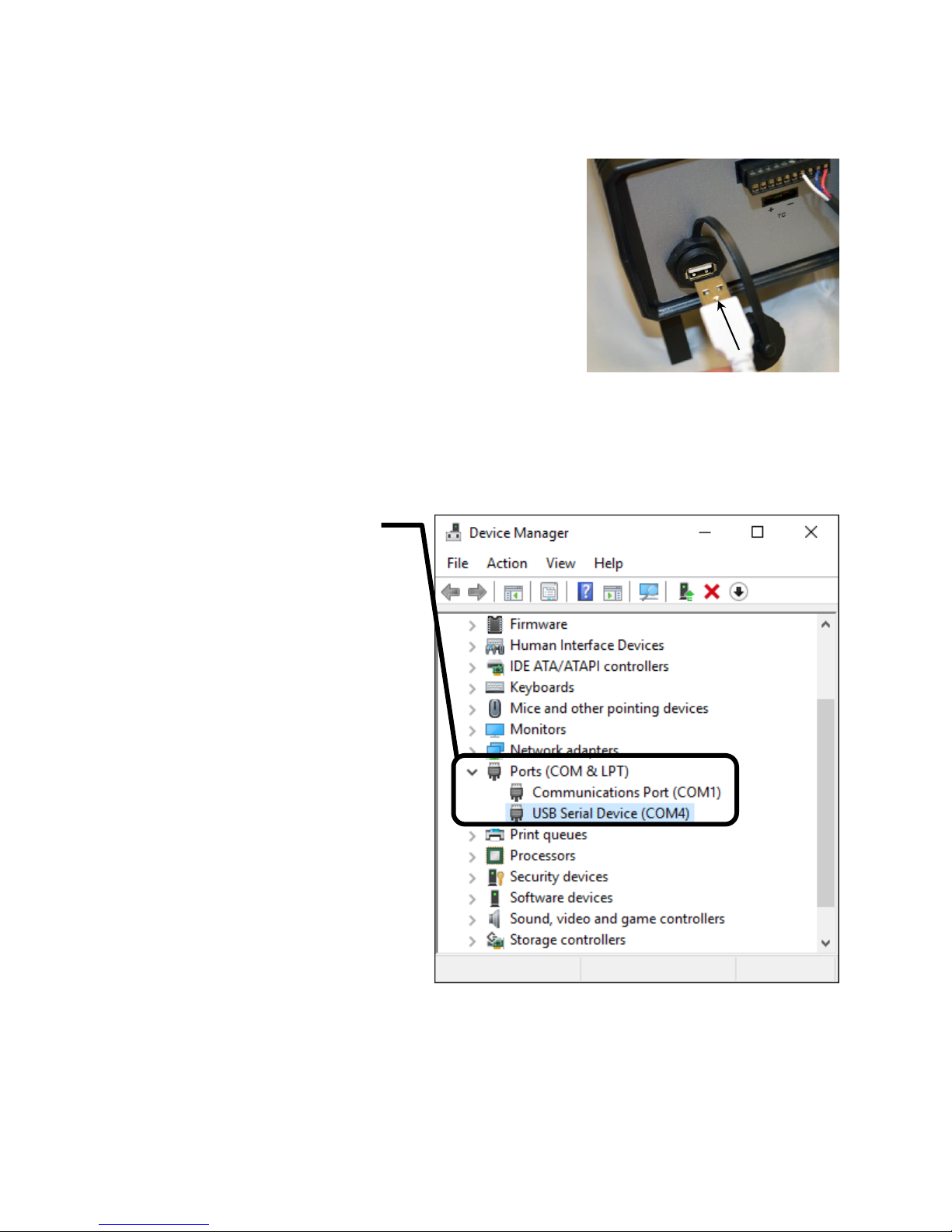
USB Cable
Connect the USB cable between the USB Type-A port on the front
panel of the TDC5 and a USB Type-A port on your host computer.
The supplied cable for this connection is a dual-ended USB Type-A
cable. Type A is a rectangular connector. (Type B is an almost square
USB connector.)
Using Device Manager to Install TDC5
1. After the TDC5 is plugged into an available USB port on the host computer, turn on the host computer.
2. Log into your user account.
3. Run Device Manager on the host computer.
In Windows® 7, you can find Device Manager in the Control Panel. In Windows® 10, you can find it by
searching in the Windows® search box.
4. Expand the Ports section in Device
Manager as shown.
5. Turn on the TDC5 and look for a new
entry that suddenly appears under Ports.
This entry will tell you the COM number
associated with the TDC5. Take note of
this for use during installation of the
Gamry Instruments software.
6. If the COM port is higher than number 8,
decide on a port number less than 8.
7. Right-click on the new USB Serial Device
that suddenly appeared, and select
Properties.
A USB Serial Device Properties window
like the one shown on the next page
appears.
14

8. Select the Port Settings tab.
9. Click the Advanced… button.
The Advanced Settings for COMx dialog box
appears as shown below. (Here x stands for the
particular port number you have chosen.)
Chapter 2: Installation
10. Select a new COM Port Number from the drop-down menu.
Select a number of 8 or less. You do not
need to change any other settings. After
you have made a selection, remember
this number to use during the Gamry
Software Installation.
11. Click the OK buttons on the two open
dialog boxes to close them.
12. Close the Device Manager by clicking on
the X in the upper right-hand corner.
13. Proceed with the Gamry Software
Installation.
14. Make sure to select Temperature
Controllers in the Select Features dialog
box during installation:
15

15. During installation, be sure
Warning: An AC-powered heater connected to a cell containing electrolyte can
represent a significant electrical-shock hazard. Make sure that there are no exposed wires or connections in
your heater circuit. Even cracked insulation can be a hazard when salt water is spilled on a wire.
to choose the TDC5 in the
Temperature Controller
Configurations Type drop-
down menu. Choose the
correct COM port that you
noted down earlier.
Chapter 2: Installation
Connecting the TDC5 to a Heater or Cooler
There are many ways to heat an electrochemical cell. These include an immersible heater in the electrolyte,
heating tape surrounding the cell, or a heating mantle. The TDC5 can be used with all these types of heaters, as
long as they are AC-powered.
The AC power for the heater is drawn from Output 1 on the rear panel of the TDC5. This output is a IEC Type
B female connector (common in the USA and Canada). Electrical cords with the corresponding male connector
are available worldwide.
Please check that the fuse on Output 1 is appropriate for use with your heater. The TDC5 is shipped with a 3 A
Output 1 fuse already installed.
In addition to controlling a heater, the TDC5 can control a cooling device. The AC power for the cooler is
drawn from the outlet labeled Output 2 on the rear of the TDC5.
The cooling device can be as simple as a solenoid valve in a cold-water line leading to a water jacket
surrounding the cell. Another common cooling device is the compressor in a refrigeration unit.
Before connecting a cooling device to the TDC5, verify that the Output 2 fuse is the correct value for your
cooling device. The TDC5 is shipped with a 5 A Output 2 fuse already installed.
16
Chapter 2: Installation
Please refer to the Omega documentation supplied with your TDC5 for information about
the various controller parameters. Do not change a parameter without some knowledge of that parameter’s
effect on the controller.
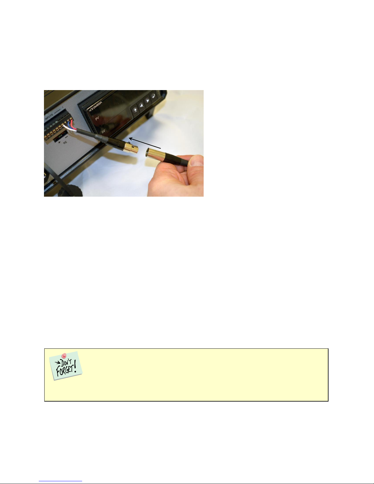
Connecting the TDC5 to an RTD Probe
The TDC5 must be able to measure the temperature before it can control it. The TDC5 uses a platinum RTD to
measure the cell temperature. A suitable RTD is supplied with the TDC5. This sensor plugs into adapter cable
supplied with your TDC5:
Contact Gamry Instruments, Inc. at our US facility if you need to substitute a third-party RTD into a CPT
system.
Place the active end of the RTD as close as possible to the working electrode in your cell. This minimizes the
effect of thermal gradients on the control accuracy.
Cell Cables from the Potentiostat
A TDC5 in your system does not affect the cell cable connections. These connections are made directly from
the potentiostat to the cell. Please read the your potentiostat’s Operator’s Manual for cell cable instructions.
Setting up the TDC5 Operating Modes
The PID controller built into the TDC5 has a number of different operating modes, each of which is configured
by means of user-entered parameters.
The TDC5 is shipped with default settings appropriate for heating and cooling a Gamry Instruments FlexCell
using a 300 W heating jacket and a solenoid-controlled cold-water flow for cooling.
Appendix A lists the factory TDC5 settings.
17

Chapter 2: Installation
18
Checking TDC5 Operation
To test the operation of the TDC5, run a simple check-out script provided with the CPT Critical Pitting Test
System. The name of this script is CHECK110.EXP. Use the procedure in the CPT Installation Manual to
perform this checkout.

Chapter 3: Use
19
Chapter 3: Use
This chapter covers normal use of the TDC5 Temperature Controller. The TDC5 is intended primarily for use in
the Gamry Instruments CPT Critical Pitting Test System. It should also prove useful in other applications.
The TDC5 is based on the Omega CS8DPT temperature controller. Please read the Omega documentation to
familiarize yourself with the operation of this apparatus.
Using Framework Scripts to Set Up and Control Your TDC5
For your convenience, the Gamry Instruments Framework™ software includes a number of Explain™ scripts that
simplify setup and tuning of the TDC5. These scripts include:
TDC5 Start Auto Tune.exp
Used to start the controller auto-tune process
TDC5 Initialize Settings.exp
Restores the TDC5 to the factory default settings
There is one downside to using these scripts. They only run on a computer that has a Gamry Instruments
potentiostat installed in the system and currently connected. If you do not have a potentiostat in the system, the
script will show an error message and terminate before it outputs anything to the TDC5.
Thermal Design of Your Experiment
The TDC5 is used to control the temperature of a electrochemical cell. It does so by turning on and off a heat
source that transfers heat to the cell. Optionally, a cooler can be used to remove heat from the cell. In either
case, the TDC5 switches AC power to the heater or cooler to control the direction of any transfer of heat.
The TDC5 is a closed-loop system. It measures the temperature of the cell and uses feedback to control the
heater and cooler.
Two major thermal problems are present to some degree in all system designs:
The first problem is temperature gradients in the cell. They are invariably present. However, they can be
minimized by proper cell design.
You cannot run any TDC5 script on a computer that does not include a Gamry Instruments
potentiostat.
Tuning the TDC5 so that it works optimally on your experimental setup is very difficult using
the front-panel controls of the TDC5. We strongly recommend that you use the scripts listed above to tune
your TDC5.

Chapter 3: Use
Stirring the electrolyte helps a great deal.
The heater should have a large area of contact with the cell. Water jackets are good in this regard. Cartridge
type heaters are poor.
Insulation surrounding the cell may minimize inhomogeneities by slowing the loss of heat through the walls of
the cell. This is especially true near the working electrode, which may represent the major pathway of escaping
heat. It is not unusual to find the electrolyte temperature near the working electrode 5–20C lower than that of
the bulk of the electrolyte.
If you cannot prevent thermal inhomogenieties, you can at least minimize their effects. One important design
consideration is the placement of the RTD used to sense the cell temperature. Place the RTD as close as
possible to the working electrode. This minimizes the error between the actual temperature at the working
electrode and the temperature setting.
A second problem concerns the rate of temperature change. You would like to have the rate of heat transfer to
the cell’s contents high, so that changes in the cell’s temperature can be made quickly. A more subtle point is
that the rate of heat loss from the cell should also be high. If it is not, the controller risks gross overshoots of the
set point temperature when it raises the cell temperature. Ideally, the system actively cools the cell as well as
heats it. Active cooling can consist of a system as simple as tap water flowing through a cooling coil and a
solenoid valve. Temperature control via an external heater such as a heating mantle is moderately slow. An
internal heater, such as a cartridge heater is often quicker.
Tuning the TDC5 Temperature Controller: Overview
Closed-loop control systems such as the TDC5 must be tuned for optimal performance. A poorly tuned system
suffers from slow response, overshoot, and poor accuracy. The tuning parameters depend greatly on the
characteristics of the system being controlled.
The temperature controller in the TDC5 can be used in an ON/OFF mode or a PID (Proportional, Integral,
Derivative) mode. The ON/OFF mode uses hysteresis parameters to control its switching. The PID mode uses
tuning parameters. The controller in PID mode reaches the set-point temperature quickly without much
overshoot and maintains that temperature within a closer tolerance than the ON/OFF mode.
When to Tune
The TDC5 is normally operated in PID (proportional, integrating, derivative) mode. This is a standard method
for process-control equipment that allows for rapid changes in the set parameter. In this mode the TDC5 must
be tuned to match it to the thermal characteristics of the system that it is controlling.
The TDC5 is shipped in a default for PID-control mode configuration. You must explicitly change it to operate
in any other control mode.
The TDC5 is initially configured with parameters appropriate for a Gamry Instruments FlexCell™ heated with a
300 W jacket and cooled using solenoid-valve controlling water-flow through a cooling coil. The tuning settings
are described below:
20

Chapter 3: Use
21
FACTORY-SET TUNING PARAMETERS
Retune your TDC5 with your cell system before you use it to run any real tests. Retune whenever you make
major changes in the thermal behavior of your system. Typical changes that may require retuning include:
Changing to a different cell,
Addition of thermal insulation to the cell,
Addition of a cooling coil,
Changing the position or power of the heater, or
Changing from an aqueous electrolyte to an organic electrolyte.
In general you do not have to retune when switching from one aqueous electrolyte to another. Tuning is
therefore only an issue when you first set up your system. After the controller has been tuned for your system,
you may ignore tuning as long as your experimental setup remains relatively constant.
Restoring Factory Settings
The TDC5 is configured using many settings (fully listed in Appendix A) which can be entered by a complicated
user interface using the four buttons on the front of the TDC5. We anticipate that anyone using this interface is
likely to scramble the TDC5 settings at least once. Various “automatic” TDC5 operations could also result in
incorrect settings, especially if they are interrupted in mid-operation.
Re-entering all the default settings manually would be time-consuming and error-prone. For this reason, Gamry
Instruments has provided an Explain script that resets all TDC5 settings to the default settings:
Start the Gamry Instruments Framework™ software.
Select Experiment > Named Script… > TDC5 Initialize Settings.exp from the Framework menu. (The
Framework script that resets the TDC5 is TDC5 Initialize Settings.exp).
When this script runs, it displays a TDC5 Quality Check window similar to that in Figure 3-1.
Figure 3-1. Initial Dialog Box Displayed by a TDC5 Script
When you click the OK button, the script sends configuration data to the TDC5.
Parameter (Symbol)
Setting
Proportional Band 1
9C
Reset 1
685 s
Rate 1
109 s
Cycle Time 1
1 s
Dead Band
14 db

Chapter 3: Use
Parameter (Symbol)
Setting
Proportional Band 1
9C
Reset 1
685 s
Rate 1
109 s
Cycle Time 1
1 s
Dead Band (db)
14
This process should take less than one minute. At the end of the transfer process, a second dialog box, similar to
Figure 3-2, appears.
Figure 3-2. Final Dialog Box Displayed by a TDC5 Script
Click the OK button to end the reset process.
Automatic versus Manual Tuning
Tune your TDC5 automatically whenever possible.
Unfortunately, the system response with many electrochemical cells is too slow for auto tuning. You cannot
auto tune if a 5C increase or decrease in the system temperature takes more than ten minutes. In most cases,
auto tune on an electrochemical cell will fail unless the system is actively cooled.
A full description of the manual tuning of PID controllers is beyond the scope of this manual. However, a later
section of this chapter does give a relatively simple step-by-step procedure for manually tuning the TDC5.
The following table contains the tuning parameters for a Gamry Instruments Flex Cell used with a 300 W
heating mantle and switched cooling using water flow though the standard cooling coil. The solution was stirred.
Auto Tuning the TDC5
We strongly recommend that you auto-tune the TDC5 as explained in the Omega® User’s Guide, section 4.6.2.
22

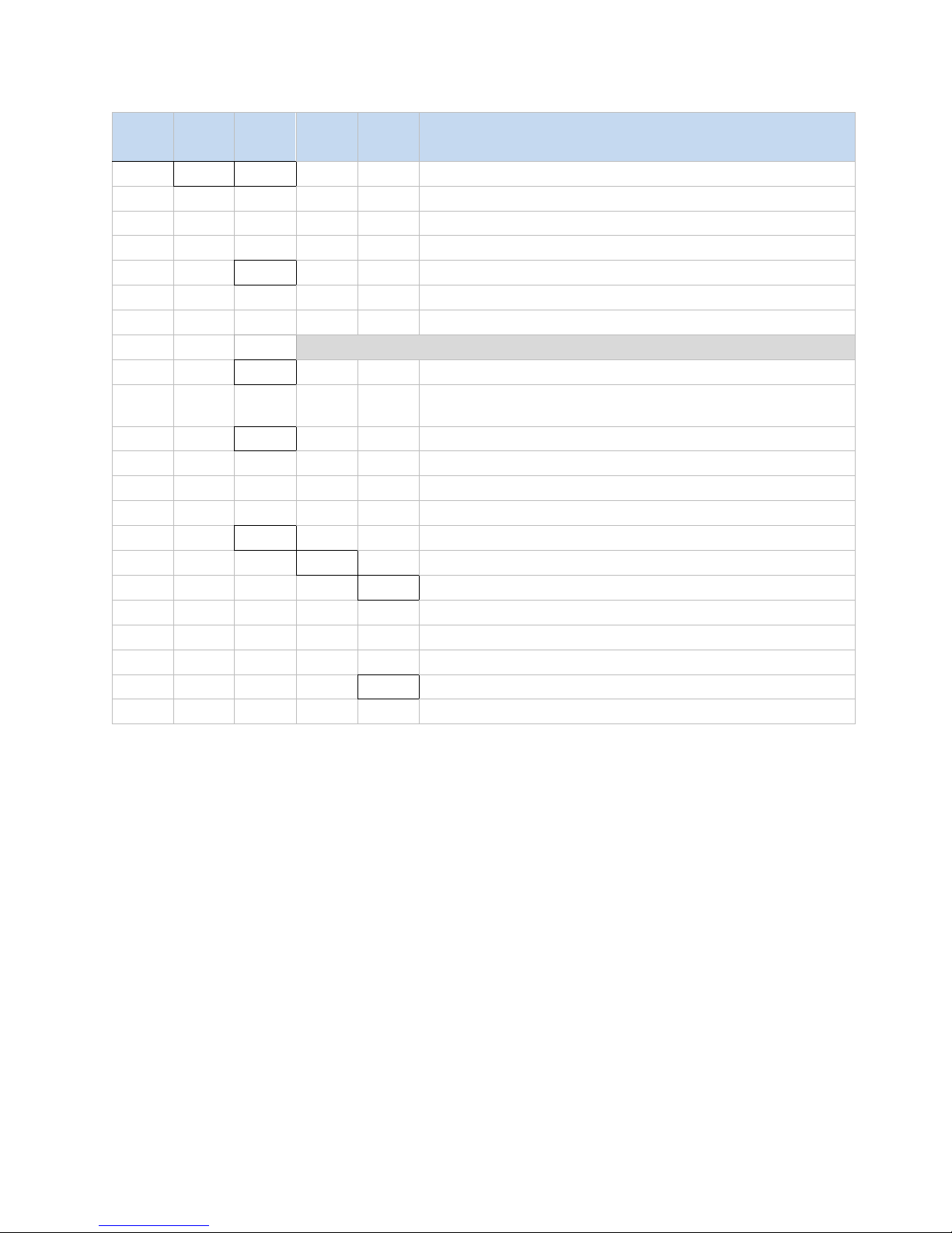
Appendix A: Default Controller Configuration
Level
2
Level
3
Level
4
Level
5
Level
6
Level
7
Level
8
Notes
INPt
t.C.
k
Type K thermocouple
J
Type J thermocouple
t
Type T thermocouple
E
Type E thermocouple
N
Type N thermocouple
R
Type R thermocouple
S
Type S thermocouple
b
Type B thermocouple
C
Type C thermocouple
Rtd
N.wIR
3 wI
3-wire RTD
4 wI
4-wire RTD
2 wI
2-wire RTD
A.CRV
385.1
385 calibration curve, 100 Ω
385.5
385 calibration curve, 500 Ω
385.t
385 calibration curve, 1000 Ω
392
392 calibration curve, 100 Ω
391.6
391.6 calibration curve, 100 Ω
tHRM
2.25k
2250 Ω thermistor
5k
5000 Ω thermistor
10k
10,000 Ω thermistor
PRoC
4–20
Process input range: 4 to 20 mA
Note: This Manual and Live Scaling submenu is the same for all PRoC
ranges.
MANL
Rd.1
Low display reading
IN.1
Manual input for Rd.1
Rd.2
High display reading
IN.2
Manual input for Rd.2
LIVE
Rd.1
Low display reading
IN.1
Live Rd.1 input, ENTER for current
Rd.2
High display reading
IN.2
Live Rd.2 input, ENTER for current
0–24
Process input range: 0 to 24 mA
+-10
Process input range: -10 to +10 V
Note: +- 1.0 and +-0.1 support SNGL, dIFF and RtIO tYPE
+-1
tYPE
SNGL
Process input range: -1 to +1 V
Appendix A: Default Controller Configuration
Initialization Mode Menu
23

Appendix A: Default Controller Configuration
Level
2
Level
3
Level
4
Level
5
Level
6
Level
7
Level
8
Notes
dIFF
Differential between AIN+ and AIN-
RtLO
Ratiometric between AIN+ and AIN-
+-0.1
Process input range: -0.1 to +0.1 V
Note: The +- 0.05 input supports dIFF and RtIO tYPE
+-.05
tYPE
dIFF
Differential between AIN+ and AIN-
RtLO
Ratiometric between AIN+ and AIN-
Process input range: -0.05 to +0.05 V
tARE
dSbL
Disable tARE feature
ENbL
Enable tARE on oPER menu
RMt
Enable tARE on oPER and Digital Input
LINR
N.PNt
Specifies the number of points to use
Note: The Manual / Live inputs repeat from 1..10, represented by n
MANL
Rd.n
Low display reading
IN.n
Manual input for Rd.n
LIVE
Rd.n
Low display reading
IN.n
Live Rd.n input, ENTER for current
RdG
dEC.P
FFF.F
Reading format -999.9 to +999.9
FFFF
Reading format -9999 to +9999
FF.FF
Reading format -99.99 to +99.99
F.FFF
Reading format -9.999 to +9.999
°F°C
°C
Degrees Celsius annunciator
°F
Degrees Fahrenheit annunciator
NoNE
Turns off for non-temperature units
d.RNd
Display Rounding
FLtR
8
Readings per displayed value: 8
16
16
32
32
64
64
128
128
1 2 2
3
4
4
Note: Four digit displays offer 2 annunciators, Six digit displays offer 6
ANN.n
ALM.1
Alarm 1 status mapped to “1”
ALM.2
Alarm 2 status mapped to “1”
oUt#
Output state selections by name
NCLR
GRN
Default display color: Green
REd
Red
24

Appendix A: Default Controller Configuration
Level
2
Level
3
Level
4
Level
5
Level
6
Level
7
Level
8
Notes
AMbR
Amber
bRGt
HIGH
High display brightness
MEd
Medium display brightness
Low
Low display brightness
ECtN
5 V
Excitation voltage: 5 V
10 V
10 V
12 V
12 V
24 V
24 V
0 V
Excitation off
CoMM
USb
Configure the USB port
Note: This PRot submenu is the same for USB, Ethernet, and Serial ports.
PRot
oMEG
ModE
CMd
Waits for commands from other end
CoNt
Transmit continuously every ###.#
sec
dAt.F
StAt
No
yES
Includes Alarm status bytes
RdNG
yES
Includes process reading
No
PEAk
No
yES
Includes highest process reading
VALy
No
yES
Includes lowest process reading
UNIt
No
yES
Send unit with value (F, C, V, mV, mA)
_LF_
No
yES
Appends line feed after each send
ECHo
yES
Retransmits received commands
No
SEPR
_CR_
Carriage Return separator in CoNt
SPCE
Space separator in CoNt Mode
M.bUS
RtU
Standard Modbus protocol
ASCI
Omega ASCII protocol
AddR
USB requires Address
EtHN
PRot
Ethernet port configuration
AddR
Ethernet “Telnet” requires Address
SER
PRot
Serial port configuration
C.PAR
bUS.F
232C
Single device Serial Comm Mode
485
Multiple devices Serial Comm Mode
bAUd
19.2
Baud rate: 19,200 Bd
25

Appendix A: Default Controller Configuration
Level
2
Level
3
Level
4
Level
5
Level
6
Level
7
Level
8
Notes
9600
9,600 Bd
4800
4,800 Bd
2400
2,400 Bd
1200
1,200 Bd
57.6
57,600 Bd
115.2
115,200 Bd
PRty
odd
Odd parity check used
EVEN
Even parity check used
NoNE
No parity bit is used
oFF
Parity bit is fixed as a zero
dAtA
8bIt
8 bit data format
7bIt
7 bit data format
StoP
1bIt
1 stop bit
2bIt
2 stop bits gives a “force 1” parity bit
AddR
Address for 485, placeholder for 232
SFty
PwoN
RSM
RUN on power up if not previously faulted
wAIt
Power on: oPER Mode, ENTER to run
RUN
RUN’s automatically on power up
RUN.M
dSbL
ENTER in Stby, PAUS, StoP runs
ENbL
ENTER in modes above displays RUN
SP.LM
SP.Lo
Low Setpoint limit
SP.HI
High Setpoint limit
SEN.M
Sensor Monitor
LPbk
dSbL
Loop break timeout disabled
ENbL
Loop break timeout value (MM.SS)
o.CRk
ENbl
Open Input circuit detection enabled
dSbL
Open Input circuit detection disabled
E.LAt
ENbl
Latch sensor error enabled
dSbL
Latch sensor error disabled
OUT.M
Output Monitor
oUt1
oUt1 is replaced by output type
o.bRk
Output break detection
dSbL
Output break detection disabled
ENbl
P.dEV
Output break process deviation
P.tME
Output break time deviation
oUt2
oUt2 is replaced by output type
oUt3
oUt3 is replaced by output type
E.LAt
ENbl
Latch output error enabled
26

Appendix A: Default Controller Configuration
Level
2
Level
3
Level
4
Level
5
Level
6
Notes
SP1
Process goal for PID, default goal for oN.oF
SP2
ASbo
Setpoint 2 value can track SP1, SP2 is an absolute value
dEVI
SP2 is a deviation value
ALM.1
Note: This submenu is the same for all other Alarm configurations.
tyPE
oFF
ALM.1 is not used for display or outputs
AboV
Alarm: process value above Alarm trigger
bELo
Alarm: process value below Alarm trigger
HI.Lo.
Alarm: process value outside Alarm triggers
bANd
Alarm: process value between Alarm triggers
Ab.dV
AbSo
Absolute Mode; use ALR.H and ALR.L as triggers
d.SP1
Deviation Mode; triggers are deviations from SP1
d.SP2
Deviation Mode; triggers are deviations from SP2
CN.SP
Tracks the Ramp & Soak instantaneous setpoint
ALR.H
Alarm high parameter for trigger calculations
ALR.L
Alarm low parameter for trigger calculations
A.CLR
REd
Red display when Alarm is active
AMbR
Amber display when Alarm is active
dEFt
Color does not change for Alarm
HI.HI
oFF
High High / Low Low Alarm Mode turned off
Level 2
Level 3
Level 4
Level 5
Level 6
Level 7
Level 8
Notes
dSbL
Latch output error disabled
t.CAL
NoNE
Manual temperature calibration
1.PNt
Set offset, default = 0
2.PNt
R.Lo
Set range low point, default = 0
R.HI
Set range high point, default = 999.9
ICE.P
ok?
Reset 32°F/0°C reference value
dSbL
Clears the ICE.P offset value
SAVE
_____
Download current settings to USB
LoAd
_____
Upload settings from USB stick
VER.N
1.00.0
Displays firmware revision number
VER.U
ok?
ENTER downloads firmware update
F.dFt
ok?
ENTER resets to factory defaults
I.Pwd
No
No required password for INIt Mode
yES
_____
Set password for INIt Mode
P.Pwd
No
No password for PRoG Mode
yES
_____
Set password for PRoG Mode
Programming Mode Menu
27

Appendix A: Default Controller Configuration
Level
2
Level
3
Level
4
Level
5
Level
6
Notes
GRN
Green display when Alarm is active
oN
Offset value for active High High / Low Low Mode
LtCH
No
Alarm does not latch
yES
Alarm latches until cleared via front panel
botH
Alarm latches, cleared via front panel or digital input
RMt
Alarm latches until cleared via digital input
CtCL
N.o.
Output activated with Alarm
N.C.
Output deactivated with Alarm
A.P.oN
yES
Alarm active at power on
No
Alarm inactive at power on
dE.oN
Delay turning off Alarm (sec), default = 1.0
dE.oF
Delay turning off Alarm (sec), default = 0.0
ALM.2
Alarm 2
oUt1
oUt1 is replaced by output type
Note: This submenu is the same for all other outputs.
ModE
oFF
Output does nothing
PId
PID Control Mode
ACtN
RVRS
Reverse acting control (heating)
dRCt
Direct acting control (cooling)
RV.DR
Reverse/Direct acting control (heating/cooling)
PId.2
PID 2 Control Mode
ACtN
RVRS
Reverse acting control (heating)
dRCt
Direct acting control (cooling)
RV.DR
Reverse/Direct acting control (heating/cooling)
oN.oF
ACtN
RVRS
Off when > SP1, on when < SP1
dRCt
Off when < SP1, on when > SP1
dEAd
Deadband value, default = 5
S.PNt
SP1
Either Setpoint can be used of on/off, default is SP1
SP2
Specifying SP2 allows two outputs to be set for heat/cool
ALM.1
Output is an Alarm using ALM.1 configuration
ALM.2
Output is an Alarm using ALM.2 configuration
RtRN
Rd1
Process value for oUt1
oUt1
Output value for Rd1
Rd2
Process value for oUt2
RE.oN
Activate during Ramp events
SE.oN
Activate during Soak events
SEN.E
Activate if any sensor error is detected
OPL.E
Activate if any output is open loop
CyCL
PWM pulse width in seconds
RNGE
0-10
Analog Output Range: 0–10 Volts
oUt2
Output value for Rd2
28

Appendix A: Default Controller Configuration
Level
2
Level
3
Level
4
Level
5
Level
6
Notes
0-5
0–5 Volts
0-20
0–20 mA
4-20
4–20 mA
0-24
0–24 mA
oUt2
oUt2 is replaced by output type
oUt3
oUt3 is replaced by output type (1/8 DIN can have up to
6)
PId
ACtN
RVRS
Increase to SP1 (i.e., heating)
dRCt
Decrease to SP1 (i.e., cooling)
RV.DR
Increase or Decrease to SP1 (i.e., heating/cooling)
A.to
Set timeout time for autotune
tUNE
StRt
Initiates autotune after StRt confirmation
GAIN
_P_
Manual Proportional Band setting
_I_
Manual Integral Factor setting
_d_
Manual Derivative Factor setting
rCg
Relative Cool Gain (heating/cooling mode)
oFst
Control Offset
dEAd
Control Dead band/Overlap band (in process unit)
%Lo
Low clamping limit for Pulse, Analog Outputs
%HI
High clamping limit for Pulse, Analog Outputs
AdPt
ENbL
Enable fuzzy logic adaptive tuning
dSbL
Disable fuzzy logic adaptive tuning
PId.2
Note: This menu is the same for PID menu.
RM.SP
oFF
Use SP1, not remote Setpoint
oN
4–20
Remote analog Input sets SP1; range: 4–20 mA
Note: This submenu is the same for all RM.SP ranges.
RS.Lo
Min Setpoint for scaled range
IN.Lo
Input value for RS.Lo
RS.HI
Max Setpoint for scaled range
IN.HI
Input value for RS.HI
0–24
0–24 mA
0–10
0–10 V
M.RMP
R.CtL
No
Multi-Ramp/Soak Mode off
yES
Multi-Ramp/Soak Mode on
RMt
M.RMP on, start with digital input
S.PRG
Select program (number for M.RMP program), options 1–
99
M.tRk
RAMP
Guaranteed Ramp: soak SP must be reached in ramp time
0–1
0–1 V
29

Appendix A: Default Controller Configuration
Level
2
Level
3
Level
4
Level
5
Level
6
Notes
SoAk
Guaranteed Soak: soak time always preserved
CYCL
Guaranteed Cycle: ramp can extend but cycle time can’t
Note: tIM.F does not appear for 6 digit display that use a HH:MM:SS format
tIM.F
MM:SS
“Minutes : Seconds” default time format for R/S programs
HH:M
M
“Hours : Minutes” default time format for R/S programs
E.ACt
StOP
Stop running at the end of the program
HOLd
Continue to hold at the last soak setpoint at program end
LINk
Start the specified ramp & soak program at program end
N.SEG
1 to 8 Ramp/Soak segments (8 each, 16 total)
S.SEG
Select segment number to edit, entry replaces # below
MRt.#
Time for Ramp number, default = 10
MRE.#
oFF
Ramp events on for this segment
oN
Ramp events off for this segment
MSP.#
Setpoint value for Soak number
MSt.#
Time for Soak number, default = 10
MSE.#
oFF
Soak events off for this segment
oN
Soak events on for this segment
Changes that Gamry Instruments Has Made to Default Settings
Set Omega Protocol, Command Mode, No Line Feed, No Echo, Use <CR>
Set Input Configuration, RTD 3 Wire, 100 ohms, 385 Curve
Set Output 1 to PID Mode
Set Output 2 to On/Off Mode
Set Output 1 On/Off Configuration to Reverse, Dead Band 14
Set Output 2 On/Off Configuration to Direct, Dead Band 14
Set Display to FFF.F degrees C, Green Color
Set Point 1 = 35 degrees C
31

Set Point 2 = 35 degrees C
Set Proportional Band to 9C
Set Integral factor to 685 s
Set Derivative factor Rate to 109 s
Set Cycle time to 1 s
Appendix A: Default Controller Configuration
32

Index
AC line cord, 7
AC Outlet Fuses, 8
Advanced Settings for COMx dialog box, 15
Advanced… button, 15
auto tuning, 22
Index
potentiostat, 17, 19
power cord, 11
power line transient, 10
power switch, 13
Programming Mode Menu, 30
Properties, 14
RFI, 9
RTD, 11, 12, 13, 17, 20
cable, 8, 12, 17
CEE 22, 8, 12
Cell Cables, 17
CHECK110.EXP, 18
COM port, 14
COM Port Number, 15
Control Panel, 14
cooler, 16
cooling device, 16
CPT Critical Pitting Test System, 11, 18, 19
CS8DPT, 7, 11, 12, 19
Default Controller Configuration, 25
Device Manager, 14, 15
electrical transients, 9
Explain™ scripts, 19
Flexcell™, 12, 17, 20
Framework™ software, 19, 21
fuse
cooler, 16
heater, 16
safety, 7
Select Features dialog box, 15
shipping damage, 7
static electricity, 9
TDC5
Cell Connections, 16
Checkout, 18
Operating Modes, 17
Tuning, 20
TDC5 adapter for RTD, 11
TDC5 Initialize Settings.exp, 19, 21
TDC5 Start Auto Tune.exp, 19
Temperature Controller Configurations, 16
Temperature Controllers, 15
Thermal Design, 19
Type drop-down menu, 16
USB cable, 11, 14
USB Serial Device, 14
USB Serial Device Properties window, 14
Use
TDC5, 19
Gamry Software Installation, 2-15
heater, 8, 9, 16, 19, 20, 21
host computer, 14
Initialization Mode Menu, 25
line voltages, 8, 12
oPER, 13
Output 1, 16
Output 2, 16
Parameters
Operating, 21
PID, 12, 17, 20, 22
Port Settings tab, 15
Ports, 14
Visual Inspection, 11
33

Redefining Electrochemical Measurement
Part #: 988-00067
734 Louis Drive
Warminster, PA 18974
Tel: (215) 682-9330
www.gamry.com
 Loading...