


Page 1
User Manual
Copyright © 2010 Gammill, Inc. All Rights Reserved

Page 2
Gammill Vision™ User Manual
Copyright © 2010 Gammill, Inc. All Rights Reserved
Publish Date: February 2010
All rights reserved. No parts of this work may be reproduced in any form or by
any means – graphic, electronic, or mechanical, including photocopying,
recording, taping, or information storage and retrieval systems – without the
written permission of the publisher.
Products that are referred to in this document may be either trademarks and/or
registered trademarks of the respective owners. The publisher and the author
make no claim to these trademarks.
While every precaution has been taken in the preparation of this document, the
publisher and the author assume no responsibility for errors or omissions, or for
damages resulting from the use of information contained in this document or
from the use of programs and source code that may accompany it. In no event
shall the publisher and the author be liable for any loss of profit or any other
commercial damage caused or alleged to have been caused directly or indirectly
by this document.
Our thanks to Pat Barry for writing this manual, and Alan Barry for many of the pictures.
__________________________________
IMPORTANT MACHINE INFORMATION
It is our goal to ensure that Customers have information on the tools and accessories
(standard and optional), that are available for use with Gammill® quilting machines.
Some of the tools and accessories detailed in this Manual may be optional equipment.
We recommend that you consult with your Authorized Gammill Dealer or Sales
Representative for the most current list of standard and optional equipment. Standard
equipment, optional equipment, and pricing are subject to change without notice.

Page 3
Table of Contents
Section 1 - Tour your Gammill Vision™......................................................................................................... 6
Gammill Vision™ - Front View ....................................................................................................................... 6
Gammill Vision™ - Right SideView ................................................................................................................ 7
Gammill Vision™ - Left Side View ................................................................................................................. 8
Gammill Vision™ - Back View ....................................................................................................................... 9
Gammill Vision™ - Top View ....................................................................................................................... 10
Gammill Vision™ - Bottom Crosstrack (aka Carriage)................................................................................. 11
Tour Your Table ........................................................................................................................................... 12
GS-1PA Table.......................................................................................................................................... 12
Home-Pro Table ...................................................................................................................................... 13
Section 2 – Getting Ready to Quilt ............................................................................................................... 13
About the manual ................................................................................................................................ 13
About the instructions.......................................................................................................................... 13
Threading the Machines .............................................................................................................................. 13
Back Section............................................................................................................................................ 14
Middle Section ......................................................................................................................................... 15
Front Section ........................................................................................................................................... 16
Threading the Gammill Vision™ 18-8 ...................................................................................................... 17
Using the On-board Bobbin Winder ............................................................................................................. 17
Winding bobbins while quilting................................................................................................................. 18
Winding bobbins before quilting............................................................................................................... 18
Using a Stand-alone Bobbin Winder ............................................................................................................ 19
About the Bobbin Case ................................................................................................................................ 19
Inserting the Bobbin Case ....................................................................................................................... 20
Setting the Tensions .................................................................................................................................... 20
Set the Intermittent Tension..................................................................................................................... 20
Set the Rotary Tension ............................................................................................................................ 21
Set the Bobbin Case Tension .................................................................................................................. 21
Checking the Top Thread Tension ...................................................................................................... 21
Changing the Top Thread Tension...................................................................................................... 22
Section 3 - Navigating The Screens ............................................................................................................. 23
Turning on (and off) the machine ................................................................................................................. 23
Initialization:......................................................................................................................................... 23
Main Screen - Carousel of Patented Applications ....................................................................................... 24
Stitcher Modes......................................................................................................................................... 24
About the Stitch-regulator - ................................................................................................................. 24
Channel Locks ......................................................................................................................................... 25
Stitch Monitor ...................................................................................................................................... 26
FM Tuner ................................................................................................................................................. 28
Tools / Diagnostics .................................................................................................................................. 29
Settings / Preferences ............................................................................................................................. 30
Main Screen - Settings................................................................................................................................. 30
Main Screen - Setting Changes............................................................................................................... 30
Main Screen - Status Information ................................................................................................................ 32
Stitcher Status Button .............................................................................................................................. 32
Needle Positioner .................................................................................................................................... 33

Page 4
Laser Light ............................................................................................................................................... 33
Automatic Tie-offs .................................................................................................................................... 34
Stitch Counters ........................................................................................................................................ 34
Bobbin Factor Icon .............................................................................................................................. 35
Bobbin Fill Gauge ................................................................................................................................ 35
Stitch Counter Icon .............................................................................................................................. 36
Run-time Clock Icon. ........................................................................................................................... 37
Section 4 - Let’s Quilt ! .................................................................................................................................. 38
Standard Procedures ................................................................................................................................... 38
Pull up the bobbin .................................................................................................................................... 38
Tie-off Stitches to Begin........................................................................................................................... 39
Continuous Line Designs......................................................................................................................... 39
Tie-off to End ........................................................................................................................................... 39
Trim.......................................................................................................................................................... 39
Explore Stitching Modes ................................................................................................................................. 40
Regulate ................................................................................................................................................. 40
Coast Regulate ....................................................................................................................................... 40
Constant ................................................................................................................................................. 41
Baste ...................................................................................................................................................... 41
Explore the Settings / System Preferences ................................................................................................. 42
Laser Light ................................................................................................................................................42
Response..................................................................................................................................................42
Coast Spread............................................................................................................................................42
Coast Threshold .......................................................................................................................................42
The 4
th
scale .............................................................................................................................................43
System Alarms......................................................................................................................................... 43
Thread Break Alarm ............................................................................................................................ 43
Too Fast Alarm .................................................................................................................................... 43
Bobbin Empty Alarm............................................................................................................................ 43
Turning Off Alarms .............................................................................................................................. 44
Needle Positioner .................................................................................................................................... 44
System Volume........................................................................................................................................ 45
Calibration................................................................................................................................................ 45
Section 5 - Quilting Techniques.................................................................................................................... 47
How To Relocate the Screen ....................................................................................................................... 47
How To Start and Stop (a line of stitching) .................................................................................................. 48
How To Restart (a line of stitching) .............................................................................................................. 48
How To Test the Tension ............................................................................................................................. 49
Adjust the bobbin tension .................................................................................................................... 49
Adjust the top thread tension............................................................................................................... 50

Page 5
Congratulations on the purchase of your new Gammill Vision™ Quilting System.
Gammill has added high tech electronics to its ‘Best of Class’ stitching mechanism,
giving you an exceptional quilting experience!
The new features incorporated into the Gammill Vision™ are a result of suggestions from
current customers plus Gammill’s dedication to providing the best quilting system possible to
meet your needs. The Gammill Vision™ is complete with options that enable you to adjust the
stitching to suit your style.
The first and most obvious improvement is the touch screen, which displays the color icons for
all of the features. Operating instructions are easier to find and understand using the new
icons. What isn’t as obvious are the technological improvements behind these features. The
new technology enables you to easily learn, use, and maintain your new quilting partner. It
also allows you to update your system as new and exciting features are added in the future.
There is a new ‘Coast’ mode that combines the stitch-regulator with constant speed for
efficient transition to micro-stitching. The stitch-regulator operates at higher speeds, but the
machine automatically switches into constant speed when the machine speed drops below the
adjustable Coast threshold. This enables you to stitch motifs using the regulator, and
automatically switch to constant speed to micro-stipple the background.
We still offer the ‘Regulated’ mode but now you can adjust it to fit your speed. High-speed
quilters are prone to getting the occasional long stitch at take-off points. Slow-speed quilters
may see extra stitches in the points. Regardless of your speed preference, you can now easily
set the regulated mode response to adjust the stitching to suit your speed.
Another step toward trouble-free quilting is the optional digital video camera. Turn on your
camera and see the stitch quality on the underside of the quilt. No more flashlights and mirrors!
There are other self-diagnostic checks occurring while you are stitching. They are happening in
the background so they don’t disrupt your stitching unless a warning is needed. The early
warning system is a true time saver.
Thank you for choosing the Gammill Vision™ – we are sure you will enjoy it!
Please read this manual before operating your new machine, even if you have used a Gammill
Quilting System before. There is some new information that will make your quilting experience
easier, and you don’t want to miss it.

Page 6
Section 1 - Tour your Gammill Vision™
This chapter is dedicated to introducing the Gammill Vision™, and some new terminology.
Some terms will be familiar and some will be new, but if you understand the terms, the
explanations included later in this manual will make more sense. Consider this section an
overview; complete instructions are in later sections.
Gammill Vision™ - Front View
Here is a picture of your state-of-the-art Gammill Vision™.
1. Main Module – displays all the instructions and icons. The Main Module is actually a separate
module that fits into a docking station that is attached to the machine. There is a docking station at the front
and at the back of the machine, so the module can be moved to the back of the machine when doing
pantographs.
Caution: Be sure to have the power off when moving the module from one end to the other.
2. Handles – there are two handles in the front and in the back, and they function the same
way. In the left handle is the Single Stitch button that controls the single stitch and needle position functions. In
the right handle is the Run button that controls the starting and stopping of the stitching. Often the right button
is red and is called the Red button.
3. Light Bar – there is a long thin light fixture attached to the handles. The light switch is on the right
side, hidden by the black guard. Flip the switch away from you to get natural light (LED). Flip it toward you to
turn on the black light (UV) which is very helpful when using glow-pencil markers or when quilting with white
thread on white fabric.
4. Needle Area – The needle bar holds the needle in place.
The hopping foot is a circular guard that surrounds the
needle. The hopping foot is more than just a safety guard. It is
instrumental in creating a good stitch, and it also allows the use of
templates and rulers. The shape makes it safe to guide the machine
along the edge of a template or ruler for a perfect stitch line or design.
The camera also helps insure a good stitch.
Needle area in front
1. Main Module
with antenna
Front Docking Station
Laser Light Plug
2. Handles:
Left handle button
is Single Stitch
Right handle button
is the ‘Run’ button to
Start/Stop stitching
3. Light Bar
Light Bar switch is underneath
on the right. (UV, off, LED)
4. Needle Area
with optional
Camera

Page 7
Gammill Vision™ - Right SideView
The right side of the Gammill Vision™ has the threading path and tension devices.
1. Thread Path – Threading the machine can seem complicated but it is actually easy because
the thread guides clearly mark the path. In this example, thread comes off the cone, going straight up
into the first guide called the thread lead-off. There are two more guides that take it into the intermittent tension
assembly, and it is wrapped around the silver cylinder (which is a thread break sensor wheel) and then to
another guide and to the rotary tension assembly. Two ‘L’ shaped guides help keep the thread in the check
spring. From there it goes to the take up lever, through more guides and finally through the eye of the needle.
Detailed threading instructions are given in the following pages.
2. Bobbin Area – is the open area below the needle. The bobbin
and bobbin case are larger than most domestic sewing
machines so they hold more thread, and run out less often.
The sewing hook (also known as hook race or hook) spins around the
bobbin, catching the thread and making the stitch. Be sure nothing ever
obstructs this motion. This area will look familiar very soon since you will
clean the bobbin area with a small brush every time the bobbin is
changed. .
3. Crosstrack – Also known as the carriage, is a platform that holds the machine. It has two
tracks so the machine can roll front-to-back. It sits on two tracks on the table which allow it to roll left to right.
The crosstrack has the vertical channel lock attached as well as one of the encoders for the stitch-regulator.
4. “T” Bar is a bracket shaped like a ‘T’ that is screwed into the side of the machine. The bracket
can hold the stylus vertically when it is being used to align the machine with a mechanical template like the
WorkStation or the Design Center. The bracket can also hold the stylus horizontally for attaching the adjustable
laser clamp when it is being used to hold the laser light while stitching pantographs.
5. Laser Light – is being held in a special clamp that allows it to be turned so it points in
virtually any direction. When attached to the ‘T’ bracket, as shown here, the laser light is used to follow
pantographs which are stitched from the back of the machine. When using the laser light at the back, plug it
into the Power Enclosure on the left side at the back of the machine. It only fits in one place on the Power
Enclosure.
The laser light and clamp can also be moved to the front for use when working at the front of the
machine, as shown in the next paragraphs.
2. Bobbin Area, 3. Crosstrack, 4. “T” bracket, 5. Laser light, 6. Pickup roller
Take-up Lever
(behind guard)
Rotary Tension
(the check spring is
inside)
Thread Guides
Needle Area
Thread Break Sensor
Intermittent Tension
Thread Lead-off
Thread Guide
Cone thread

Page 8
6. Pick Up Roller – will hold the quilt layers after they are quilted. It must be located inside the throat
space to ensure the machine can move freely. It starts out small – taking just a few inches but as the quilt
nears completion, the size increases and this reduces the amount of quilting space left free for stitching.
Gammill Vision™ - Left Side View
The left side of the Gammill Vision™ has an on-board bobbin winder.
1. Bobbin Winder – How convenient it is to wind bobbins while you stitch so they will be
ready when you need the next one! The bobbin winder has a thread path, which travels from the
cone of thread, up through the guides, through the tension assembly and over to the bobbin. The bobbin
sits on a post that will spin when the machine is stitching. The bobbin winder lever is lowered into the
bobbin. As the bobbin fills, the lever is pushed up and will eventually pop up, stopping the bobbin winder
from turning
.
2. Laser Light – has been moved from the back of the machine to the front. It is still being
held by the adjustable laser clamp that allows easy adjustments, but now it is attached to a post on the
top of the machine. In this position, it is easy to follow stencils and block patterns. The light plugs into the
bottom side of the front Docking Station and the wire is held by the white clips, preventing it from touching
the front hand wheel.
This close-up picture shows the
Camera bracket (attached)
and
Camera assembly (plugged in).
Plug in H Channel lock. 5. Vertical Channel lock
4. Horizontal Channel lock. and its plug
3. Encoder for stitch-regulator 6.Camera connection
2. Laser Light with
adjustable laser clamp
Front hand wheel
Laser light front plug
Clips (to hold laser light wire
away from the hand wheel.)
1. Bobbin Winder
Tension Assembly
Thread Lead-off
Bobbin Winder Lever
Bobbin
Power Enclosure
Thread Cone

Page 9
3. Encoder – The stitch-regulator has two encoders that
‘ride’ the wheels and measure how fast the machine
is moving and in which direction, so it knows when to
make the next stitch. The encoder riding the wheel on the
machine monitors the Vertical movement (front to back). There is
another encoder that is located on the underside of the
crosstrack that monitors the horizontal movement (side to side).
Between these two encoders, the stitch-regulator can determine
when to stitch.
4. Horizontal Channel Lock – is a magnet attached to the side of the machine that locks
onto the crosstrack preventing it from moving forward and backward, hence the
Horizontal lock. The channel lock is set on and/or off by touching the icon on the screen.
The lock plugs into the adjacent electrical plug on the side.
5. Vertical Channel Lock – is a magnet attached to the front of the crosstrack that locks
onto the table preventing it from moving side to side, hence the Vertical lock. The
channel lock is set on and/or off by touching the icon on the screen. The lock plugs into
a wire connection at the front of the crosstrack. This cable at the back of the crosstrack
plugs into the right side of the Power Enclosure.
6. Camera connection – The larger of the two electrical plugs is for the camera connection.
Each plug has a unique shape so it can only fit in one place.
Camera Assembly
The camera assembly is held in place by a bracket that screws into the side of the
machine. It takes a video image of the under side of the quilt so you can examine the stitch
quality on the back. The camera also has both LED (white) lights and UV (black) lights to
help you see the stitches on the back of the quilt. The bracket looks like it is touching the
crosstrack, but it is not.
Gammill Vision™ - Back View
The machine can be operated from either the front or the back. All handle buttons remain active
regardless of the Main Module’s location.
1. Main Module and the rear
Docking Station. The screen can
be moved to the back dock very
easily, as shown. Lightly pull it straight
up to remove and reverse to install.
Camera assembly is plugged in, and the
lights are on.
The camera lens is in the middle.
The image will be displayed on the screen.
Encoders:
Vertical
Horizontal

Page 10
2. Handles on the back operate
just like the handles on the
front; The Single Stitch button is in
the left handle and the Run button is
in the right handle.
3. Vertical Spool Holder Extension
– is 4" long, and is located on top
the regular spool holder. It is used for
small spools or cones of cross-wound
thread.
4. Power Enclosure, cords, and
connectors - Each of the cords can
connect in only one spot, so getting
the machine plugged in is easy.
Gammill Vision™ - Top View
The top of the machine contains the power switches and more.
1. Motor - is mounted toward the
back of the machine. The motor
turns a belt which has a black plastic
covering for safety.
2.
Power and Motor Switches are
mounted in the middle. They can
easily be reached when standing in the
front or the back of the machine. Turn
power on first, then motor.
3.
Post - In front of the switches is the
post for the laser light. This is where
the laser is attached when working at the
front of the machine.
3. Post for laser mount
1. Motor
2. Power and Motor
switches
1. Main Module
(at rear)
Rear Docking Station
2. Handles & buttons
Left is single stitch
Right is Run
4. Power Enclosure
cords and connectors
3. Vertical Spool Holder
Extension
The Vision™ uses standard household current (110, grounded).
A high quality surge protector is recommended to protect your
investment.

Page 11
Gammill Vision™ - Bottom Crosstrack (aka Carriage)
Each machine has a special platform called a crosstrack or carriage, which allows the
machine to move freely around the table. The crosstrack has channel locks which use
magnets to stop the machine from moving. It also has encoders that detect and measure
motion which is an important element of the stitch size regulation. The machine’s wheels fit
into tracks on the crosstrack, enabling the machine to move front to back. The crosstrack’s
wheels fit into tracks on the table, enabling it to move side to side.
Tracks (also called rails) are specially designed to allow the wheels to move smoothly. There
are two tracks on the crosstrack (for the machine’s wheels) and two tracks on the table (for the crosstrack’s
wheels).
3. “H” and “V”
Channel locks
(See Page 9)
2. “X” and “Y”
Encoders
(See Page 9)
1. Tracks
Page 12
Tour Your Table
The Gammill Vision™ is available in three sizes; V18-8, V26-10, V30-12. The first number is
the distance in inches from the needle to the back of the throat area, and the second number
is the height of this space. The tables used for the Gammill Vision™ are the same as the
tables used for the same size Plus (stitch regulated) or Standard (non-stitch regulated)
machines.
The V18-8 is paired with the Home-Pro table, which is available in 10’ and 12’ lengths. The
V26-10 and the V30-12 require the GS1 table. The standard size for the GS1 table is 12’ but
custom lengths are available.
GS-1PA Table
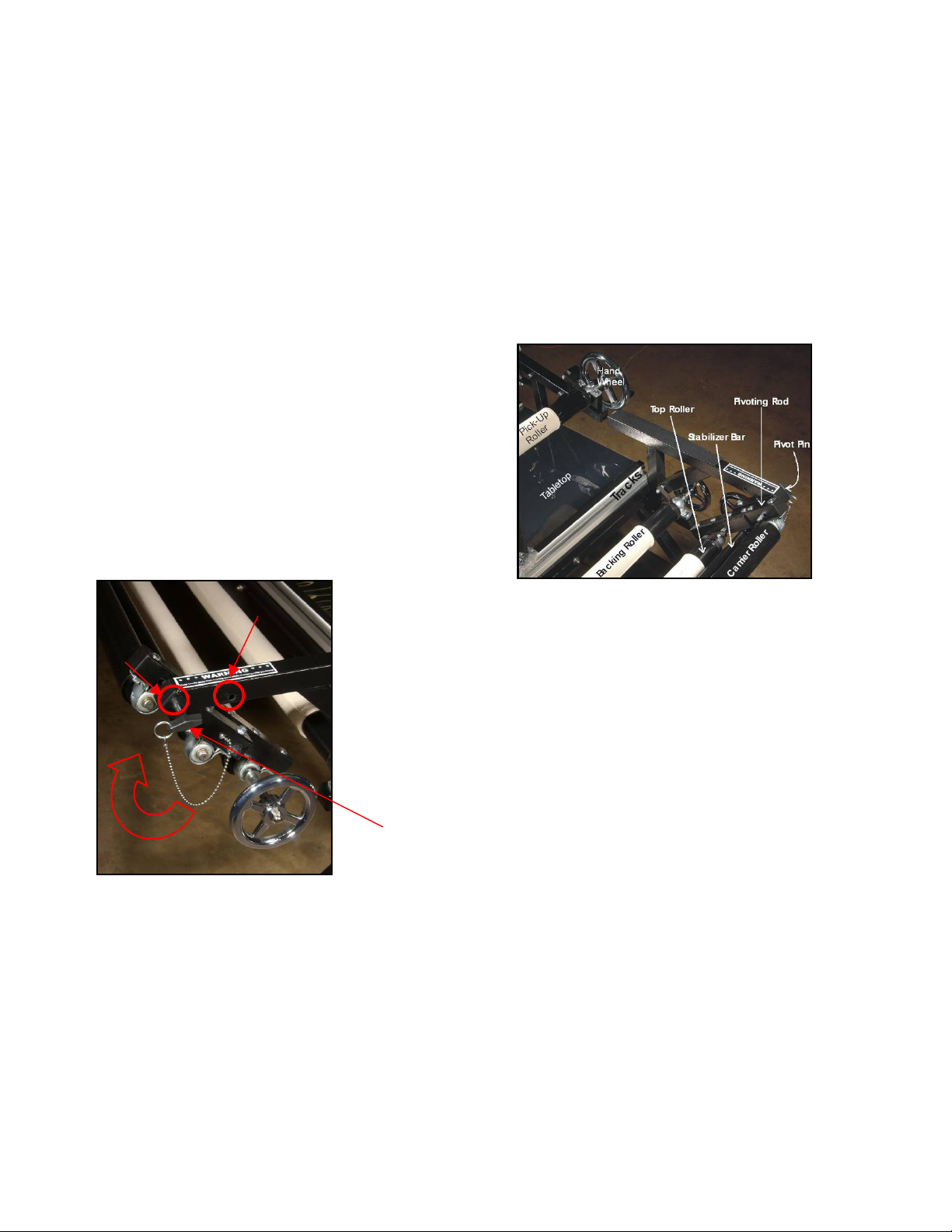
This close-up picture shows the right side of the table, with many of the parts labeled.
1. The PA Assembly is incredibly useful! It can be released (just pull out the pivot pin) so it
can pivot the top roller up, exposing the batting and backing layers. This is very useful for
removing stray threads and smoothing the batting layer.
2. It has two fixed positions; Quilt and Load. When in Quilt position, the PA assembly is
slanted back, making it comfortable to sit while quilting. The picture shows the quilt position. In
load position, the PA assembly is vertical, not slanted, which makes the quilt layers easier to load. To
switch from one to the other, remove the pivot pin, reposition the PA assembly and re-insert the pin.
Leaders are strips of canvas that are attached to
three rollers; Pickup roller, Backing roller and the
Top roller.
The layers of the quilt will be attached to the canvas
leaders using pins, zippers, hook & loop tape, or even
plastic staples!
When fabric is loaded, these three rollers hold it
taut using locking levers (dogs) that fit into the
gear shaped end of each roller, near the hand
wheel.
This picture shows the right side of the table from a
different perspective.
1. The Pivotal Access (PA) Assembly consists of the
metal bar holding the three rollers
Top roller (with the hand wheel)
Stabilizer bar
Carrier bar (or belly bar).
2. Also shown is the pivot pin, and the two pivot
pin holes which control the angle of the assembly.
Quilt Position
Load Position
GS1 Table Parts

Page 13
Home-Pro Table
• Instructions are either numbered or listed as bullet points.
• Each set of instructions might be prefaced with a paragraph of ‘Prep Steps’ so you know
what needs to be done before you start the process.
• Often the instructions have some tips or suggestions that are printed in a smaller font.
• ‘Your Turn’ means you should take a few minutes and try the exercise.
• Many instruction sets are followed by a paragraph entitled ‘Beyond the Basics’ which
introduce alternative methods or techniques that you might want to try in the future.
As you grow in experience and exposure, you are sure to find different methods of performing
basic quilting techniques. There are certainly many ways to do these techniques and the ones
described here are (hopefully) simple and clear.
Threading the Machines
Now that you have taken a quick tour of your new quilting system, it is time to thread the
machine. There may still be some new terminology, but the text and pictures should help
define them.
The Home-Pro table is perfect for home use
and has a very sturdy metal frame. The
rollers, leaders, table top and crosstrack all
function in the same way as the GS-1PA table.
Section 2 – Getting Ready to Quilt
Now that you have been introduced to your new Gammill Vision™ quilting system, it is time to
get ready to quilt. The previous section defined many new terms – most of them were names
for the various parts of your quilting system. There will be more new terms, but since you know
the names of the machine parts, the new terms will make more sense.
About the instructions
The following sections provide step-by-step instructions and lots of good tips.

Page 14
The Gammill Vision™ 26-10 and 30-12 have the same thread path. The V18-8 is a little bit
different as we will see later in this section. Complete details are given by area, beginning with
the cone of thread at the back of the machine and working forward. Enlarged areas are often
photographed from a different perspective so the details will be shown more clearly.
Back Section
1. Draw some thread off the cone. Take it
straight up and into the first thread guide called
the thread lead-off.
Thread is wound onto a cone in a crisscross
method and needs to have it drawn off by
pulling the thread straight up so it does not twist.
2. Follow the twist of the metal and put the
thread through the second eyelet in the guide,
from the back to the front. See the enlarged
diagram.
3. The thread goes through another guide a few
inches forward.
Looking at the thread
lead-off from
behind shows it has
two eyelets.
Front Middle Back

Page 15
Middle Section
4. Bring the thread forward and through the thread
guide that is attached to the intermittent tension. If
this assembly were a clock, the thread guide
would be positioned at about 3:00.
When the stitcher is running, the intermittent
tension actually moves in and out about 1/32”.
This action is intended to add tension at just the
right time to aid in pulling the thread up from the
bottom of the quilt. This action makes it harder to
pull thread from the thread spool and easier to pull
thread from below the quilt, preventing loops. This
is a patented feature on the Gammill Vision™ 2610 and the Gammill Vision™ 30-12 (the Gammill
Vision™ 18-8 does not have this stroking feature
on the intermittent tension).
5. Wrap the thread clockwise around the tension
assembly once (which is really about 80% of the
way). The thread should fit inside the two blue gray tension disks.
Be sure the thread always stays between these
two disks because when it slips out, the under side
of the quilt will have poor tension. If the tension is
too tight, the thread will quickly work its way out of
the disks.
6. Bring the thread back to the thread break sensor and wrap it counterclockwise 1 ¾
turns. The thread will sit inside a “V” shaped track. This sensor turns when the machine is
stitching. If it stops turning for 50 stitches,
the Thread Break Alarm will sound.
.
Sometimes the Thread Break Alarm will
sound even if the top thread has not
broken. Stiff or slippery thread can slip out
of the track. Running out of bobbin thread
can also cause the alarm to sound.
7. Pull the thread forward to the next thread guide, bringing it down through the first hole and
up through the third hole.
5. Looking at the intermittent tension from
behind shows the thread guide, adjustment
knob, tension spring and the thread nestled
inside the two blue / gray tension disks.
Note: The Intermittent Tension Baseline setting
is when the adjustment knob is flush with the
inside threaded shaft.
Adjustment Knob
Tension spring
Tension disks
4. Thread guide
7. From guide toward
Rotary Tension.
6. Around Thread Break
Sensor 1 ¾ times

Page 16
Front Section
8. Bring the thread down, over the Top (right angled) bracket.
9. Wrap the thread around the rotary tension assembly 1 3/4 in a
clockwise direction, making sure the thread stays in the “V” shaped
track. The thread path is not quite two full rotations.
11. Bring the thread back down and under the Bottom (angled) bracket. As you pull on the
thread, the check spring will move from about 10:30 to 9:00 position, and back.
12. The thread then goes through the eyelet in the take-up lever (hidden behind the guard)
from back to front.
13. Bring the thread down, through the remaining thread guides.
14. Thread the needle, from front to back.
Bey ond the Ba sics -
Tip for easy thread changes – When you need to change the thread, don’t pull the current
thread out and rethread using the new color. Instead, go to the back of the machine and cut
the thread even with the top of the cone. Remove the original cone and replace it with the new
color. Draw off some thread from the new cone, and securely tie the ends of the two colors
together. Now, go the front of the machine, take the thread out of the needle, and pull on the
thread until the new color is in place. Cut off the knot and rethread the needle.
Important! Check that the new color thread is still securely tucked into the intermittent tension
disks and that it is still in the track around the thread break sensor, and rotary tension
assembly.
Top bracket
Check spring
Bottom bracket.
“V” Thread track
Tension spring
Adjustment knob
Threaded Shaft
Looking at the rotary tension from above shows the
brackets, guides and check spring.
10. Guide the thread up far enough so it catches the wire of
the check spring. The check spring has a ‘U’ shape, and it moves a
bit. Gently move the check spring down and forward to make it easier
to get the thread into the ‘U’ shape.
Note: The Rotary Tension Baseline setting is when the adjustment
knob is flush with the inside threaded shaft.

Page 17
Threading the Gammill Vision™ 18-8
Threading the smaller, V18-8 machine is virtually the same.
Using the On-board Bobbin Winder
This feature allows you to wind bobbins either
while you are quilting, or not. The bobbin
winder uses its own cone (or small cone) of
thread, so if you have two cones of the same
color, you can wind bobbins while you quilt. If
you don’t have two cones of the same color,
you can wind bobbins before you begin to
quilt.
1. Draw some thread off the cone on the left side of the
machine. Just like before, take it straight up and into the first
thread lead-off guide.
2. Follow the twist of the metal and put the thread through
the second eyelet in the lead-off guide, from the back to the
front.
3. The thread goes through another guide a few inches
forward.
4. The thread must go under the tension disk and through the guide on the other side. Don’t
wrap the thread around the tension disk. Keep the thread in the lower half only. Sometimes it
Go ahead and thread the machine. Pay special attention to how the thread fits
into the tension assemblies. Rotate both tension knobs until they are flush with
the screw they surround. This is the normal ‘Start’ position for all tension
adjustments. Pull on the top thread, and notice the resistance – that is good!
You r
Tur n
There is one extra thread guide in the front, however.

Page 18
is easiest to thread the first tension disk guide, then the second, and pull a loop around to the
bottom of the tension disks, and then pull on the thread from both sides to get the thread to
pass between the tension disks.
5. Bring the thread forward through the next thread guide and
up to the on-board bobbin winder.
Winding bobbins while quilting
1. Place an empty bobbin on the bobbin winder spindle. There
is a little wire spring on the end of this spindle that will hold the
bobbin in place. If you look closely at an empty bobbin, you will
see a small notch on the inside edge.
2. Don’t try to align the wire with the notch. Just push the bobbin onto the spindle and then turn
the bobbin until it clicks into place.
3. Wrap the thread clockwise around the center of the bobbin 6-8 times, securing the end.
4. Push the bobbin winder arm down. It will slide to the inside of the bobbin. Now, bring it back
up about ¼”, so it is not touching the center of the bobbin.
5. Now, when you begin to quilt, the bobbin will wind. When the bobbin is full, the arm will pop
up and the bobbin will stop revolving.
The bobbin should not be soft and mushy, but it also should not be so tight that you can’t feel a
little give when pressing on the thread with your fingernail.
Winding bobbins before quilting
If you need to wind bobbins before you begin to quilt, you will be running the machine from the
Diagnostics screen.
Detailed instructions for using the Diagnostics are in the next section, so don’t worry if you
don’t understand the following steps yet – You will!
1. Load an empty bobbin as described above.
2. Be sure the bobbin case is not in the machine.
3. Remove the thread from the needle and take-up lever.
Wrap it around the foam covering of one of the handles. This prevents tangling.
4. Choose Diagnostics from the Initial Screen carousel.
5. Change the speed setting to about 30-50%.
6. Start by pressing the red button in the Upper Left Corner of the screen.
7. When the bobbin is full, it will stop winding automatically.
8. Turn the machine off.
9. Remove the bobbin.
Bey ond the Ba sics – If you are familiar with the previous stitch regulated machine called
the ‘Plus’, you may wonder if Constant speed can still be used to wind bobbins. The answer is
‘yes’ but it is easier to use the Diagnostics screen – and – you won’t be adding to the stitch
counter like you would if you were using the Constant Stitch mode.

Page 19
Using a Stand-alone Bobbin Winder
One of the Gammill available accessories is a stand-alone
bobbin winder. Just like the on-board bobbin winder, the
stand-alone winder has a cone thread holder, a tension
assembly, bobbin post and a bobbin-fill lever and arm. In
addition, this winder has a foot pedal, motor and electrical
cord.
Batting was placed behind various parts to help display the details.
The bobbin post, fill lever and arm are shown below.
* When in the ‘Open’ position, the fill lever is straight up, and
the fill arm is angled down so there is enough room for the
empty bobbin to be pushed onto the bobbin post.
* When in the ‘Closed’ position, the fill lever is angled forward and the fill arm moves up into
the bobbin, without touching either side.
Batting was placed behind various parts to help display the details
1. Cone thread is mounted on the holder and the thread is drawn straight up and around the
thread guide, then down to the tension assembly.
2. The thread goes through the eyelet, around and between the tension disks, clockwise.
3. Draw the thread back toward the empty bobbin and wrap it around 6-8 times, clockwise.
4. Step on the foot pedal to start the motor and fill the bobbin.
5. When the bobbin is full, the Bobbin Fill Lever will pop to the Open position and the bobbin
winder will stop winding.
About the Bobbin Case
Once the bobbin is wound, it can be inserted into the bobbin
case. The bobbin case is similar to those used with domestic
sewing machines, but larger (size M), so it holds more thread.
Exactly how much more depends on the thickness of the
thread. Our bobbin case also has a thin metal piece inside
called an anti-backlash spring. This prevents the bobbin
Follow the steps (1-5) above to wind a bobbin.
* Adjust the tension knob if needed. Right to tighten, Left to loosen.
Remember, the bobbin should not be soft and mushy, but it also should
not be so tight that you can’t feel a little give when pressing on the thread
with your fingernail.
* If the thread pops out from between the tension disks, it is too tight.
You r
Tur n
Bobbin post and Fill Lever
Cone thread holder
Tension assembly
Motor Foot pedal
Electric Cord
Tension Assembly
Closed
Open
Bobbin Post
Bobbin on post
Bobbin Fill lever
Bobbin Fill arm
Tension Bar,
Thread slot
Tension screw

Page 20
thread from over-spinning when the machine comes to a
sudden stop.
A bobbin fits easily into the bobbin case, and should spin freely, in a clockwise direction. The
case has a thin metal tension strip with two screws. The smaller one is holding it on to the
case, and the larger one adjusts the tension – right to tighten and left to loosen. When making
adjustments, turn the screw about 5 -10 minutes of a revolution at a time.
Inserting the Bo bb in C as e
There is a spring loaded handle on the outside of the bobbin
case and part of this sticks out about 1/8”. When inserting the
bobbin case, align this bump to the notch in the rotary hook
assembly (about 4:00 position). Push in the case and listen for
the click to verify that it is properly inserted.
Hint: Use the spring loaded handle to remove the bobbin, but
don’t use it to insert the bobbin because it often prevents the
‘click’, which is your assurance that the bobbin case is in
properly.
Setting the Tensions
The following text contains concepts that a novice quilter may not know yet, but don’t worry.
Tension setting concepts are explained here, and reviewed again in the Techniques Section which includes exercises on checking the tension. By then you will have learned how to load a
quilt and run the machine. The concepts are reviewed again in the Care Section - which
includes troubleshooting suggestions for poor stitch quality.
A good stitch is a balanced stitch. This means little or no thread from one side shows up on the
other side. Factors other than tension may make the stitch look imperfect. If the batting is very
thin, or the threads are very thick, or the two thread colors are very different it will be almost
impossible to not see the thread from the other side.
Start with a thread made specifically for longarm quilting machines. A&E’s PermaCore 30 wt
thread is a great choice for the beginning quilter. This has a poly core that gives it strength,
and durability. Once you have bonded with your machine you can try other brands / types /
weights.
Set the Interm it te nt T en sion
• The In termittent Tension B aseline setting is when the adjustment knob is flush
with the inside threaded shaft, so start there.
• Intermittent tension adjustments might be needed on every quilt combination you do
because the thread, fabric, batting and backing all affect the stitch quality. Turn the
thumb screw to the right (clockwise) to tighten and the left to loosen. When adjusting
the tension, always turn the intermittent tension knob at least ½ turn at a time. It's a
coarse adjustment and less than ½ turn will not appreciably change the tension.
• If the tension is too tight, the thread will quickly work its way out of the disks.
Rotary hook shaft and notch

Page 21
• Be sure the thread stays nestled between the two tension disks. If it slips out, the
quilt will have poor tension.
Set the Rota ry T en si on
• The Rotary Tension Baseline setting is when the adjustment knob is flush with the
inside threaded shaft, so start there.
• The Rotary Tension should remain loose – just tighten it enough so the wheel rotates
when stitching. Turn the thumb screw to the right (clockwise) to tighten and the left to
loosen. Once this is set, it rarely needs to be changed.
Set the Bobb in C as e Te nsion
The ‘Bo bbin Basel ine’ for tension is determined like this:
1. Put a full bobbin into the bobbin case, place it in your hand
flat, so the bobbin can be seen. Pull on the thread and
make sure the bobbin is rotating clockwise.
2. Slide the thread through the slot and under the tension strip,
until it is coming out of the small space in the side.
The first time you use a new thread type, size or brand:
1. Tighten the tension screw on the bobbin case first (so the bobbin and case lifts off your
hand when you pull on the thread slowly).
2. Loosen gradually (loosen the tension screw 10 minutes at a time until the bobbin case
remains in your hand when you pull the thread slowly).
3. Adjust if needed (tighten the tension screw 5 minutes to make sure you didn’t overloosen the bobbin).
When refilling the bobbin:
• After inserting a full bobbin, try to pick the bobbin case up by the thread. The tension should
be tight enough to turn the bobbin case onto its side. And, it should be on the verge of
coming off your hand but should not lift off your hand. Adjust as needed.
Checking the Top Thread Tension
1. Start with a properly tensioned bobbin case.
2. Attach a test piece.
3. Pull up the bobbin, tie-off and stitch at a normal
speed. Include some soft curves, tight spirals,
straight lines (horizontal and vertical) and sharp
points. Look closely at the stitch quality.
4. Remove the pins and check the underneath too.
Properly loaded bobbin &
case turns on its side but does
not lift up off the surface.
Attach a test piece.

Page 22
Changing the Top Thread Tension
• If the tension is poor on the back of the quilt - top thread loops, bobbin thread laying
flat, eyelashes or stitches not embedding in the fabric - then tighten top tension ½
turn at a time to "pull" the stitch (the bobbin and top thread connection) into the
middle of the quilt.
• If tension is poor on top then check the bobbin case first. If it seems OK, loosen the
intermittent tension ½ turn at a time until stitch balance is achieved.
Check the stitch
quality
on the back also.
Stitch:
soft curves
tight spirals
straight lines
sharp points

Page 23
Section 3 - Navigating The Screens
Turning on (and off) the machine
If the machine is not turned on yet, do it now. Plug in the power cord using an extension if
needed. Please use a high quality surge protector! Locate the two switches on the top of
your machine. Always turn the Power on first, and the Motor on second. (O is OFF, and I is
ON). Reverse this order when turning the machine off. Each switch is labeled, using the
universal symbols for ‘Power’ and ‘Motor’. These universal symbols may not be familiar to you,
so it might be good to label your machine with the words instead of the icons. It really is
important to do this in the correct sequence.
The machine will take about 10 seconds to load the firmware. Firmware is a new term, which
means the Gammill Vision™ system isn’t just hardware, and it isn’t all software, it is a
combination of both – consider it a really smart quilting machine.
Initialization:
During the Initialization process, the Gammill Vision™ will perform some internal diagnostic
checks. The progress bar shows it is loading. Be patient – it may take a minute.
When it is done, it will display the Main Screen which is a touch screen which means you don’t
need a mouse or keyboard to initiate any of the features, you just touch the icon on the screen.
There are three important areas of the Main Screen:
1. Carousel of Icons - for all the features.
2. Settings – for current activity.
3. Status Information – for quick review.
The stitching feature icons are displayed in a circular
fashion, called a carousel. The icon at the front of the
carousel is the active icon. It is the only carousel icon
that can be initiated. Touching any of the background
icons in the carousel will do nothing.
Main Screen
2. Settings
ON : 1st the Power 2nd the Motor
These icons are the
universal symbols for :
Power
Motor
OFF : 1st the Motor 2nd the Power

Page 24
The green arrows are used to rotate the carousel, until the desired icon is at the front. The left
green arrow will rotate the carousel clockwise and the right rotates it counterclockwise.
Often times touching an icon will bring up a secondary screen, which presents more options for
you to choose. You don’t have to make a choice – you can return to the primary
screen just by pressing the Exit Icon (that looks like a door).
Main Screen - Carousel of Patented Applications
Touch the screen and get the icons to revolve. It may feel awkward at first, but you will soon
appreciate the fact that you don’t have to memorize any codes or key sequences. The icons
are all in front of you! Here is a list of icons, and what they do.
Stitcher Modes
About the Stitch-regulator -
There is one position on the carousel for the stitch-regulator, but four modes within the stitch
regulation software. Pressing the ‘Regulate’ Icon will rotate through the choices.
Regulate – means every stitch will be the same length – or as close as
possible. The encoders measure the speed and direction of the wheels and
feed the information back to the software, which calculates when to take the
next stitch. The target is to have every stitch exactly the same.
Coast – means the stitch-regulator is used at higher speeds but not at the
lower speeds. This allows the quilter to stitch motifs using the stitch-regulator,
and then slow down to do micro-stitching without the regulator (constant
speed). This eliminates the need to stop and turn off the regulator when
moving from the designs to the backgrounds or detail work.
You r
Tur n
Coast
Press Regulate
to change to
Constan
Press Coast
to change to
Press Constant
to change to
Baste
Regulate
Press Baste
to return to
Main Screen
The Main Screen starts with the Regulate icon in front.
The icon in the front determines how the stitcher will respond.
• To change the mode, press the icon once, and the next
stitch mode will be presented.
• Repeat until the desired mode appears.
Go ahead and try turning the carousel.
Touch the green arrow to move the
carousel counterclockwise as you read
the following section.
You r
Tur n

Page 25
Constant – means the stitcher is stitching at a constant pace, without regard
for the movement of the machine (aka sewing head). The encoders are not
sending movement information to the software. The stitch length will vary,
depending on how fast the operator moves the machine.
Baste – means to take very large stitches, similar to doing a sequence of
single stitch. These are measured in inches per stitch instead of stitches per
inch.
When using any of these stitching choices, the machine won’t begin to quilt until the stitcher
is started. Use the buttons in the handles or press the Stitch Button. When the stitcher is
running, the color of the Stitch Button changes.
Channel Locks
Bey ond the Ba sics: When both the horizontal and vertical channel locks are locked, the
machine will not move. This is very convenient when replacing the bobbins.
The Horizontal Channel Lock icon is next. It looks like an
open padlock with the letter “H”. That means the channel
lock is ‘off’. A closed padlock indicates the lock is ‘on’.
You r
Tur n
Press the icon to lock
the machine so it only
moves side-to-side.
Press the icon
again to unlock
The Vertical Channel Lock icon is next. It looks like an
open padlock with the letter “V”. That means the channel
lock is ‘off’. A closed padlock indicates the lock is ‘on’.
You r
Tur n
Press the icon to lock
the machine so it only
moves front-to-back.
Press the icon
again to unlock
Stitch Button (red) shows the stitcher is off.
Stitch Button (green) shows it is on.
Thanks to the stitch-regulator, even when
the stitcher is ‘on’ it won’t stitch until you
move the machine.
Page 26
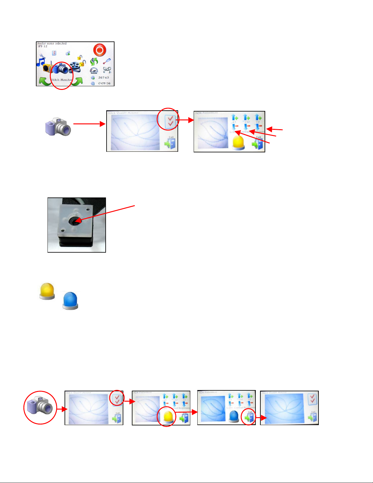
Stitch Monitor
Press the Settings Icon to adjust the camera settings if desired.
One of the camera settings is a light icon.
Try both types of lighting and choose the one with the clearest image.
1. Press the Camera Icon, and wait a few seconds for the image to appear.
(be sure the machine and camera lens are over/under the quilt).
2. Press the Camera Settings Icon.
3. Press the Camera Light Icon (yellow to blue or blue to yellow).
4. Press Exit to see a larger screen image.
The Stitch Monitor icon is next. The monitor uses a digital
video camera to view the stitch quality, and displays the
image right on the screen.
The Camera eye is in the middle of the white collar.
LED (white) lights are on each side.
UV (black) lights are on the top and bottom.
Camera Closeup
The Yellow refers to the daylight, or white LED light.
The Blue refers to ultraviolet lighting, or black UV light.
The following series of screen shots shows the effect of changing the lighting.
Adjust if needed.
Brightness.
Contrast
Light,

Page 27
The color of the thread and fabric impact the image clarity too. Try changing the Light intensity,
contrast and/or brightness to get the clearest image.
1. Press the Camera Settings Icon again to adjust other camera settings.
2. Change the Light intensity, Contrast and/or Brightness by touching the scales.
Touch the up arrow to increase, and the down arrow to decrease.
The adjustments take effect immediately, so fine tuning the picture is fast and easy.
3. Press Exit when done to see the larger image
4. Press Exit again to return to the stitching.
Bey ond the Ba sics: When working at the front of the
machine, put the laser light on the front mount, and point the
laser at the camera lens. This helps to identify the exact
placement of the camera image.
Press the Camera icon to show the image on the screen. (It takes a few seconds)
Position the machine over some quilted area of the quilt.
Look at the screen image of the underside.
Change the light choices (LED to UV and back)
Press up / down arrows to adjust the image quality if desired.
Press Exit to return to the monitor screen.
Press Exit to return to the Main Screen.
You r
Tur n
Camera eye is 3 ½” to
the left of the needle.
Page 28
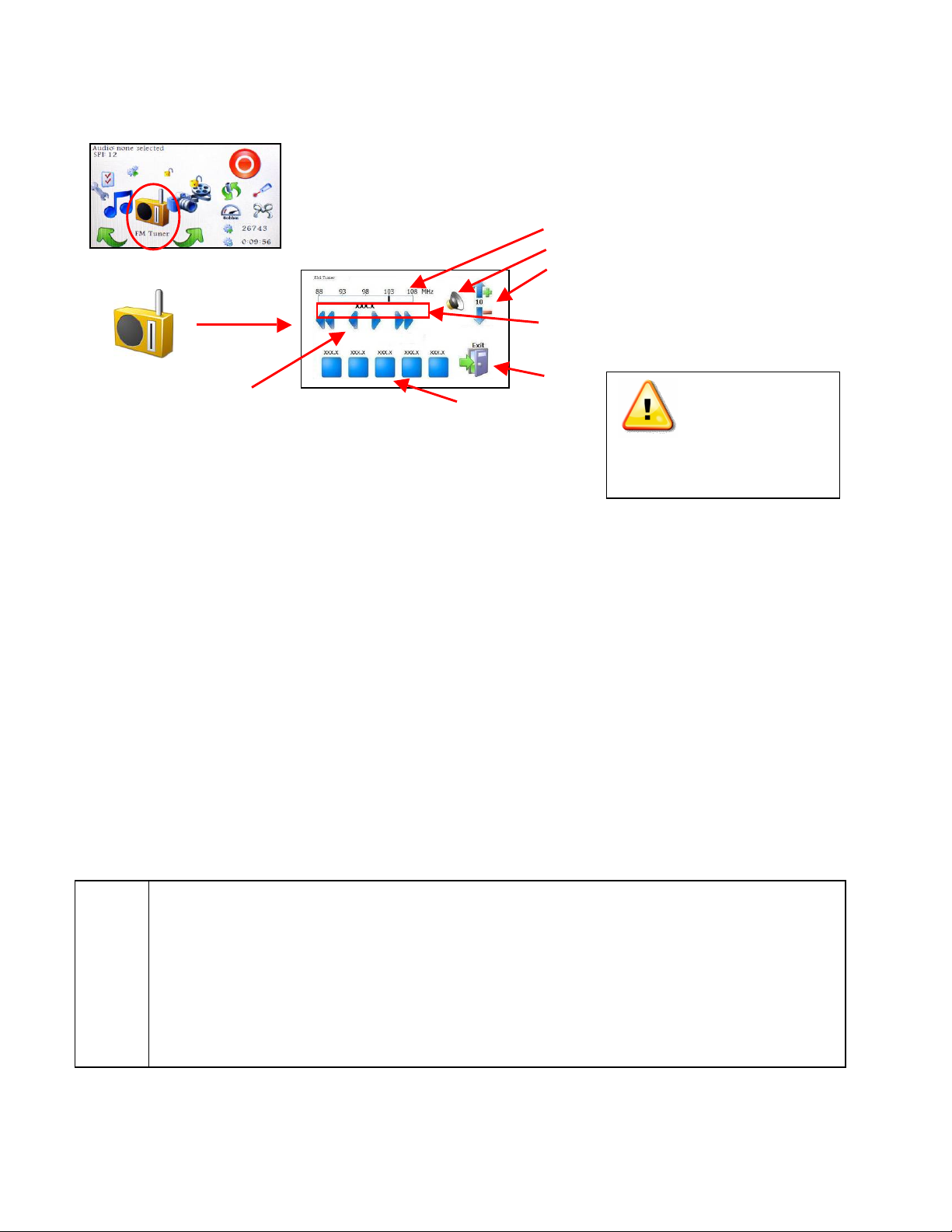
FM Tuner
To turn the radio On,
1. Press the FM Tuner Icon to display the radio dials.
2. Press the Speaker Icon to turn on the speaker.
3. Use the scan buttons to look for a station on the FM band.
• Scan Forward and Scan Reverse go to the next station.
• Step Forward or Step Reverse change the setting 0.1 MHz at a time.
• If the signal strength is > 30%, the call numbers will appear on the screen
(if the radio station transmits that information).
4. To Set one of the radio buttons, press it firmly and hold (just like a car radio)
5. Press the up / down arrows on the Volume scale to raise/lower the volume.
6. Press Exit to return to the Main Screen.
Note: Some radio stations can broadcast the song name and artist.
If your radio station has this capability, it will appear just above the FM band.
To turn the radio Off,
1. Press the FM Tuner Icon to display the radio dials.
2. Press the Speaker Icon to turn the speaker off.
3. Press Exit to return to the Main Screen.
Find your favorite radio station, and set one of the five buttons.
Press the FM Tuner icon to display the radio dials.
Press the speaker icon to turn it on, Use the Scan buttons to find a station.
Press and hold one of the Preset Buttons until you hear the bell.
Press Exit to close the screen.
To turn off the radio, Press the FM Tuner icon again,
Press the speaker icon again to turn it off, and then Press Exit.
You r
Tur n
The FM Tuner works just like an FM radio. This is a great option
for people who enjoy listening to the radio while they quilt.
Scan buttons
(Scan Reverse, Step Reverse, Step Forward, Scan Forward)
FM Radio Band
Speaker (on / off selector)
Volume Scale
Your chosen station frequency
call number and sometimes the
song title and artist appear.
Exit
Turn Power Off
before raising antenna
Or removing the module.

Page 29
Tools / Diagnostics
From this screen you (and your technician) will be able to check the operation of your machine.
These checks are explained in detail in the maintenance section of this manual – just an
overview is given here:
1. Stitcher On/Off button
2. Motor Power setting-to adjust to desired speed during maintenance and bobbin winding.
3. Virtual Position - shows machine head movement testing the x, y encoder sensors.
When the machine head is moved, this dot will move also.
4. Needle Position sensors –
The red dot on the top – turns green when the needle is at its highest point.
The red dot on the bottom – turns green when the needle is at its lowest point.
5. Exit – return to the Main Screen.
6. Handle Button Sensors – verify that the machine is acknowledging the pressing / and
releasing of the buttons in the handles.
7. Motor Diagnostics – are tests “For dealer/technician use only”
8. Motor Direction – Clockwise arrow shows forward, counter-clockwise shows reverse.
In Section 2, you learned how to wind bobbins before you begin to stitch. Review the details in
that section if needed because here is your chance to try it!
The Tools / Diagnostics icon is next. Diagnostics are tests that
check the operation of your machine and stitcher.
1. Stitcher On/Off button
2. Motor Power Setting
3. Virtual Position
4. Needle Position Sensors
5. Exit
6. Handle Button Sensors
7. Motor Diagnostics – for Dealers and Technicians only
8. Motor Direction
Wind a bobbin using the On-board winder (review the details given in Section 2).
1. Load an empty bobbin.
2. Remove the bobbin case.
3. Remove the thread from the needle & take up lever.
Wrap it around the foam covering of one of the handles. This prevents tangling.
4. Choose Diagnostics from the Main Screen carousel.
5. Change the motor speed setting to about 30-50%.
6. Make sure the motor is in forward position.
7. Press Start
8. When the bobbin is full, it will stop automatically.
9. Turn off the motor
10. Remove the bobbin.
You r
Tur n

Page 30
Settings / Preference
s
Main Screen - Settings
The upper left corner of the Main Screen displays the
settings for features currently active.
This example shows us that there is no audio active,
and that the current stitch size is 12 SPI.
It also shows the current stitch mode is ‘Regulated’.
If the current stitch mode was Coast, SPI would be displayed, just like Regulated mode.
If the current stitch mode was Constant, the Speed would be displayed in the Settings area.
If the current stitch mode was Baste, the IPS (Inches Per Stitch) size would be displayed.
Main Screen - Se tt in g Ch anges
From the Main Screen, you can change the stitch size setting for any current stitch mode.
• Touch the screen in the upper left corner area and
another dialog box appears.
• Touch the up arrows on the scale
to increase or decrease the setting.
• Press Exit to return to the Main Screen.
Go ahead and look at the System Preferences.
Most of these values are new to you, so please don’t change them yet.
Press Exit to return to the Main Screen.
You r
Tur n
The Settings / Preferences icon is next. This is where you set
your preferences as defaults. It is a good idea to learn how the
features work first, and then determine your preferred settings.
Some of the settings are explained as you learn each feature.
The rest are explained in detail, at the end of the next section.
Main Screen
Regulated Stitch Mode

Page 31
Regulated and Coast Regulated both use SPI (Stitches Per Inch) as the setting displayed on
the Main Screen. Any changes to the Coast Speed or Coast Threshold need to be done using
the Carousel Settings Icon.
Coast Regulated Stitch Mode
The range for Regulated is 8-24
SPI.
Constant Stitch Mode
The range is 1-100% motor power.
Baste Stitch Mode
The Baste Range is ½ to 4 IPS
(Inches Per Stitch) in ½”

Page 32
Main Screen - Status Information
Now that you have been introduced to all of the icons on the carousel, it is time to look at the
status information on the right side of the Main Screen.
Each of these icons displays the status of a frequently used piece of information so they need
to be easily accessible. The most important status icon is the Stitcher Status Button which is
also the most prominent and the most commonly used.
Several of the other icons represent counters that can be reset. Touching the lower right
corner of this screen will display a parameter screen that allows us to reset these counters
when needed. All of this will be explained in detail on the following pages.
Stitcher Status Button
The icons are color coded like a stop light, but also contain a symbol to
differentiate them for people who are color blind. The red button has a
‘0’ (or a circle) in it and the green button has a ‘1’ (or a line) in it. These
are the Universal symbols for On and Off, respectively.
The Stitcher Status Button in the upper right corner
shows when the stitcher is Off or On.
This is important since the stitcher is so quiet.
Remember, the stitcher does not stitch unless it is
being moved, so it could be ‘on’ even though it is
not actively stitching.
As a safety feature, stitcher will turn itself off if it
has not been moved in 3 seconds.
On
Off
To change the Stitcher Status, press the Stitcher Status Button on the
screen -OR- press the right handle button. Press it again to turn the stitcher
off.
You r
Tur n
Main Screen
Parameter Screen
Stitcher is Off

Page 33
Needle Positioner
This icon looks like the left machine handle. That is because the
needle positioner determines how the button in the left machine
handle operates. To turn the needle positioner on, you can touch
the "Needle Positioner" Icon on the main screen.
Two green arrows mean the needle positioner is off, so the left handle button makes
a complete stitch every time it is pressed.
One green and one red arrow mean the positioner is on so the left handle button
button makes a half stitch every time it is pressed. If the needle is in the ‘up’ position,
pressing the button once makes it go down, and stay there, in the fabric. Press it
again, and the needle returns to the ‘up’ position. This is helpful when quilting because it
holds the machine in place, not allowing it to move (and draw off extra thread).
If the needle is in the ‘down’ position when starting a continuous line of stitching, it will return to
the ‘down’ position when the stitching is stopped. This is especially useful with templates
because it prevents the machine from moving when you need to reposition the template or
adjust your grip.
Laser Light
The laser light can be used when working at the back of the machine or in the
front. When working in the back doing pantographs, the laser light is held by a
clamp attached to the “T” bracket on the side of the machine. When in this
position, the light plugs into the black plastic Power Enclosure casing in the
back.
When working in the front of the machine doing free motion work, the laser
light clamp attaches to the post at the top of the machine, near the front. When
in this position, the light plugs into the front docking station.
Touch the needle positioner icon on the main screen. Note the color change.
Press the left handle button to see how the needle responds when the positioner
is on and off.
You r
Tur n
Back mount
Front mount
Touch the laser icon on
the Main Screen to turn
the light on and off.
You r
Tur n
Laser is On
Laser is Off
Regardless of where the light is positioned,
it is turned off or on by touching the icon.

Page 34
Automatic Tie-offs
A truly unique feature of the Gammill Vision™ is the ability to do perfect tieoffs. This minimizes the size of the tie-off knot and makes it practically
invisible. And, it is so easy!
Press the Tie-off Icon on the Main Screen and the countdown window appears.
Press the Stitcher status button to begin. The status button turns green, but you must move
the machine just a bit to start the tie-offs. It will take 6 stitches at 30 stitches per inch and stop
stitching. When ready, you can continue your quilting, using any of the stitcher modes.
Stitch Counters
The last three icons in the lower right corner are all numeric counters of some kind. There is a
Bobbin Fill Gauge which is an estimate of when the bobbin thread is likely to run out, a Stitch
Counter that accumulates the number of stitches taken and a Run Time Clock which counts
the minutes spent stitching. Each of these numeric counters can be reset so you can collect
metrics on each quilt you do.
Touch the screen in the vicinity of the numeric counters and a parameter screen appears. It is
this parameter screen that allows you to reset any/all of the counters and begin the counts
anew. It also contains another scale “Bobbin Factor” that helps estimate when the bobbin will
Main Screen
Bobbin Fill Gauge
Stitch Counter
Run Time Clock
Parameter Screen
Main Screen
Practice doing tie-offs at the beginning and ending of a quilted design.
• Move the machine into position and pull up the Bobbin thread.
• Touch the Tie-off icon to start the beginning tie-off knot.
• Touch the Stitcher Status button.
• Move the machine just a little and the tie-off stitches will begin.
• When it stops, cut the threads.
• Choose any stitching mode, stitch a design, and stop.
• Touch the Tie-off icon to start the ending tie-off knot.
• Touch the Stitcher Status button.
• Move the machine just a little and the tie-off stitches will begin.
• Pull up the Bobbin thread and trim the threads.
You r
Tur n

Page 35
run out. Since threads vary in size or thickness, the amount of thread on a bobbin can vary
also. The Gammill Vision™ estimates the amount of thread on the bobbin, using the bobbin
factor that you set.
The Bobbin Factor scale ranges from 1 to 50.
Press the top arrow to increase (more thread) and the bottom arrow to decrease (less thread).
Bobbin Factor Icon
Change the Bobbin Factor every time you change the bobbin thread weight.
To do this:
1. Press the Bobbin Icon to display the Parameter Screen.
2. Press the Up or Down arrows to adjust the scale.
3. Press the Exit when done.
Bobbin Fill Gauge
Bey ond the Ba sics: Use the Bobbin Factor settings to adjust for partial bobbins. If you are
using a thread with a factor of 40, you have run out of bobbin, and you only have a half-full
bobbin left, go ahead and use it, but change the factor to 20. Doing this will enable you to use
the bobbin tracking capabilities even with partial bobbins.
Bobbin Fill Gauge
Every time a full bobbin is used, be sure to reset the Bobbin Fill Gauge.
To do this:
* Press the Bobbin Icon on the Main Screen to display the Parameter screen.
* Press the Bobbin Icon on the Parameter Screen to reset the counter.
* Answer the question:
“Do you really want to reset the parameter?”
Yes if you are sure (press green circle)
No if you are not (press red circle)
* Press Exit when done to return to the Main Screen.
Parameter Screen
Set the Bobbin Factor to your favorite thread size.
• Press the bobbin Icon to display the Parameter screen.
• Press the up and down arrows to change the setting.
The default of 40 works well for most standard longarm quilting machine threads.
• Press Exit when done.
You r
Tur n
Reset Stitch Counter
Reset Bobbin Fill Gauge
Reset Run Time clock
Bobbin Factor
Parameter Screen

Page 36
Any time you reset any counter, the machine will ask : “Are You Sure?” Instead of showing the
words ‘Yes’ or ‘No’, it will display two status dots. Green means ‘Yes’ and red means ‘No’. Just
press the dot that conveys your answer.
Stitch Counter Icon
People are often interested in the number of stitches taken on their quilt. By
resetting the counter before every quilt, you can provide this information.
To Reset the Stitch Counter:
• Press the Stitch Counter Icon on the Main Screen to display the Parameters.
• Press the Stitch Counter Reset Icon to reset the counter.
• Answer the question: “Do you really want to reset the parameter?”
If you answer ‘Yes’ the Parameter Screen will show a Stitch Count of zero.
• Press Exit when done to return to the Main Screen.
Press the bobbin Icon to display the Parameter screen. Press the bobbin
reset icon to reset the counter. Press the green button to confirm that you
really do want to reset the bobbin counter. Press Exit when done.
You r
Tur n
• Press the stitch counter to display the Parameter screen.
• Press the stitch counter reset icon to reset the counter.
• Press the green button to confirm you do want to reset the counter,
or the red button if you don’t.
• Press Exit when done.
You r
Tur n
Red is always a negative answer (Ex: Off, No, Stop, Cancel)
Green is always a positive answer (Ex: On, Yes, Go, OK)
Main Screen
Parameter Screen
Main Screen
Parameter Screen

Page 37
Run-time Clock Icon.
It is possible to track the total amount of time spent stitching a quilt. The run-time
clock only records the time when the machine is stitching. This is a really good
method for tracking time and measuring productivity and for the maintenance of
your machine. Be sure to reset the counter before beginning and record the time
when done.
To Reset the Run-time Clock:
• Press the Run-time Clock Icon on the Main Screen to display the Parameters.
• Press the Run-time Reset Icon on the Parameter Screen to reset the counter.
• Answer the question: “Do you really want to reset the parameter?”
The Parameter Screen will change, showing Run-time of zero hours, minutes & seconds.
• Press Exit when done to return to the Main Screen.
• Press the Run-time to display the Parameter screen.
• Press the Run-time Reset icon to reset the clock.
• Press the green button to confirm that you want to reset the run-time
clock or press the red button if you don’t.
• Press Exit when done.
You r
Tur n
Main Screen
Parameter Screen

Page 38
Section 4 - Let’s Quilt!
In this section, you will learn how to do some standard procedures: Pull up the bobbin, take
Tie off stitches, Trim and more. You are encouraged to spend some time trying each of the
stitching modes so you can set your own preferences, which are explained in depth at the
end of this section.
Pre p Steps: The power is on, fabric is loaded, side clamps are attached, machine is
threaded and the bobbin is inserted.
Work With The Handle Buttons -
The stitching mechanism (also called the ‘Stitcher’) will not start unless you press one of the
buttons in the handles.
To take a single stitch, use the Single Stitch button (in left
handle). Press and release the button to take one stitch.
To begin to stitch continuously, use the Run button (in right
handle). Press and release the button to begin a line of
stitching. Move the machine at a controlled pace.
To stop stitching, use the same Run button in the right
handle. Press and release the Run button to stop.
Standard Procedures
There is a Logical Sequence of Steps that most quilters follow when quilting. These steps are
described here, with specific instructions on how to perform each one. The standard name for
these procedures is given in ‘Quotes’.
Pull up the bobbin
1. Bring both threads to the top side to prevent knots on the underneath.
Vision - Front View
If the fabric is loaded, but you haven’t secured the top edge yet, do it now.
Use the basting feature to take a series of big stitches across the top.
Remove any pins that are still in the quilt top.
You r
Tur n
(If needed, move the machine on to the fabric. The fabric will fit under the hopping foot.)
To begin, hold the thread with one hand and take a single stitch. Without
letting go of the top thread, move the machine away 6-8 inches. The top
thread pulls up the bobbin thread. This is called “ Pulling up the bobbin”.
You r
Tur n
#1

Page 39
Tie-off Stitches to Begin
2. Hold both threads and take some tiny stitches so the stitches won’t come undone later.
Continuous L in e De sign s
3. Start the stitcher and move it to stitch the design in one continuous line.
Tie-off to End
4. At the end of the stitching, more tiny stitches are made to secure the threads,
Trim
5. Finish by bringing the bobbin thread to the top side and trim the threads.
All of the steps above will be used repeatedly, throughout this text and throughout all of the
instructions for different quilting techniques. From this point forward, these steps will be
referred to by name only. So if you see an instruction that says ‘Pull up the bobbin thread’, it is
assumed that you know how to do it.
Hold both threads with one hand. Touch the Tie-off Icon (white bow), move
the machine just a bit, and it will take 6 tiny stitches, almost on top of each
other. These stitches secure the thread so you can trim off the extra thread,
and the stitches will not come undone. Do this at the beginning and end of
each line of quilting. These are called “Tie-off Stitches”.
You r
Tur n
#2
Push the machine away about 6-8 inches. Pick up the top thread, and
without letting it go, bring the machine back and do one last stitch on top of
the tie-offs. Still don’t let go of the top thread, and push the machine away
again about 6-8 inches. The bobbin thread will come to the surface as a
loop. Trim all the threads flush with the quilt top. This is called ‘Trim’ .
You r
Tur n
#5
Touch the Stitcher Icon (or press the button in the right handle) to start.
Move the machine at a comfortable pace, making a few loops, drawing a
leaf or writing a name. These are examples of “Continuous Line Designs”.
To end, stop moving the machine and Touch the Stitcher Icon again (or
press the button in the right handle again).
You r
Tur n
#3
Touch the Tie Icon (white bow), move the machine just a bit, and it will take
6 tiny stitches, almost on top of each other. These “Tie-offs” can’t be right
on top of each other or they won’t lock. They must have a couple threads of
the fabric to anchor them.
You r
Tur n
#4

Page 40
Explore Stitching Modes
Touch the green arrows on the Main Screen and get the
icons to revolve until ‘Regulate’ is in front. Now, by
touching the Regulate Icon, it is possible to rotate through
the different stitching modes.
‘Regulate’ means the stitches will be the same length – or as close as possible.
The stitch-regulator encoders measure the speed and direction of the wheels and
feed the information back to the software, which calculates when to take the next
stitch. The target is to have every stitch exactly the same size.
‘Coast Regulate’ means the stitch-regulator is used at higher speeds but not slow speeds.
The Coa st Thresho ld is the speed where the stitch-regulator smoothly
transitions into constant speed (or vice versa). The non-stitch regulated stitching
speed is called the Coa st Speed.
The Coast mode allows the quilter to stitch designs using the stitch-regulator, and then slow down
to do micro-stitching the background in Coast speed (like constant) without having to stop the
machine to switch modes. The Coast Speed and Coast Threshold can be changed in the Setting \
Preferences.
Pull up the bobbin thread. Take a few tie-off stitches, using the Tie-off Icon.
Choose Regulated mode of stitching.
• Press the right handle button to begin stitching.
• Move the machine around to get the ‘feel’ of it.
• Move it a little faster to make it stitch faster and notice the stitches
are the same length.
• Press the right handle button to stop the stitcher.
• Tie-off and trim the threads.
You r
Tur n
Pull up the bobbin thread. Take a few tie-off stitches using the Tie-off Icon.
Choose Coast mode of stitching. Be prepared to move the machine as soon
as you begin because it will start in Constant speed.
• Begin. Increase your speed until the stitch-regulator starts. It will
behave just like regulated mode.
• Slow down gradually. At some point (called the Coa st Thresho ld),
the machine begins to stitch at a constant speed.
• Speed up again, and the stitch-regulator kicks in again.
• Stop, tie-off and trim the threads.
You r
Tur n
Main Screen
Regulate
Coast Regulate
Constant
Baste

Page 41
Both Regulate and Coast Regulate share a new feature – the “Too Fast” alert. This is a
System Alarm that warns you if the machine is moving faster than the stitch-regulator can
stitch accurately. The machine will sound three short chimes, and if the movement continues to
be fast, the triple chime will be repeated, until the motion slows. This alarm can be disabled by
accessing the Settings \ Preferences \ System Alarms, described in the next few pages.
‘Constant’ means the machine is stitching at a constant rate, without regard for the
movement of the sewing head. The encoders are not sending movement
information to the software. The stitch length will vary, depending on the
operator only.
‘Baste’ means to take very large stitches, similar to doing a sequence of single stitches.
These are measured in inches per stitch (IPS) instead of stitches per inch (SPI).
Basting is often used to secure the three layers together at the edges. If the
basting stitches are going to be removed, don’t use the automatic tie-offs
because they are too hard to remove.
Pull up the bobbin thread. Take a few large tie-off stitches if the basting will be removed.
Choose Baste mode of stitching.
• Press the Run button (in the right handle) to begin stitching.
• Move the machine around to get the ‘feel’ of it.
• Stop, tie-off if needed and trim the threads.
You r
Tur n
Pull up the bobbin thread. Take a few tie-off stitches.
Choose Constant mode of stitching. Be prepared to move the machine as
soon as you begin.
• Press Start and begin to quilt.
• Moving the machine very slowly makes tiny stitches.
• Moving the machine fast will make big stitches.
• Stop, tie-off and trim the threads.
You r
Tur n

Page 42
Explore the Settings / System Preferences
Now that you have learned how to operate the machine, it is time to set your own stitching
preferences. The four scales at the top of the Preferences screen relate to the stitcher
mechanics. The following text describes the differences but all quilters have their own ‘touch’.
The settings that work for one person may or may not work for you. Practice using different
settings and see which ones you prefer.
Turn the Carousel until the Settings Icon is in front.
Laser Light This is an alternative method of turning the laser light On/Off. Press the icon
once to turn it off. Press it again to turn it back on. Press Exit when done. The easier method is to
use the Main Screen (see pink dashed line).
Response This is how fast the stitcher responds to changes in operating speed. The
range is between 1 and 10. Press the ‘up’ arrow to increase, the ‘down’ arrow to decrease and
press the ‘Exit’ Icon when done.
• If the setting is on the low end of the scale, it means the machine will accelerate at a slower
rate. This is a good choice for people who tend to change speeds slowly.
• If the setting is on the high end, it means the machine will respond faster, and is less likely to
have long stitches coming out of the corner.
Coast Speed This is the motor speed used when stitching slowly in Coast mode. The range
is from 1-100% motor power. Press the ‘up’ arrow to increase, the ‘down’ arrow to decrease,
and press ‘Exit’ when done.
Coast Threshold This is the transition speed when the Coast mode switches between
regulated and non-regulated stitch lengths. The range is 1–100 %. Press the ‘up’ arrow to
increase, the ‘down’ arrow to decrease, and press ‘Exit’ when done.
Beyond the Basics: Coast Speed and Coast Threshold work together and are best
explained together. Assume that the Coast Threshold is 30, the Coast Speed is 20 and the
Coast SPI is 12. This means the first stitches will be done at a constant motor speed of 20%,
Needle Positioner Motor Calibration
System Volume
Laser Light On or Off
Response 1 to 10
Coast Speed 1 to 100
Coast Threshold 1 to 100
4th Scale varies, depending
on the current Stitch Mode
System Alarm
Exit
Press Settings Icon and the
Preferences Screen appears

Page 43
and as soon as the free motion motor speed exceeds 30%, the stitch-regulator kicks in and all
the rest of the stitches will be consistently 12 Stitches/Inch. If the speed drops to below 30%,
the stitch-regulator stops, constant speed resumes at 20% motor speed.
The 4th sc al e This defines the stitch size using parameters that vary by stitch mode.
If mode is Regulated then the 4th scale is labeled SPI (Stitches/inch)
If mode is Coast Regulated then the 4th scale is labeled SPI Coast (Stitches/inch)
If mode is Constant then the 4th scale is labeled Speed (Motor power %)
If mode is Baste then the 4th scale is labeled IPS (Inches per stitch)
An alternative method is to use the Main Screen when
changing the stitch size for the current stitching mode. Just
touch the upper left corner of the Main Screen, and make the
change in the dialog box that appears. Press Exit when done.
This was explained in the previous section - Explore Stitching
Modes.
System Alarms
There are three system alarms that can be used if desired: Thread Break alarm, Speed alarm
and Bobbin Empty alarm. Each is a series of three chimes, in rapid succession. The chimes
will repeat if the issue is not resolved. A warning message also appears when a thread break
is detected.
Thread Break Alarm
The actual Thread Break Sensor on the machine is a small
silver cylinder that spins freely. When stitching, the thread
moves from the intermittent tension to the rotary tension
assembly and spins this cylinder. If the cylinder is not moving
when stitching, the Gammill Vision™ assumes the thread has
broken, and an alarm is triggered after 50 stitches and a
warning message appears on the screen.
On occasion it is nice to turn this off – for example when slick thread is being used and it slips
in the sensor’s wheel. If slipping in the wheel is an issue you might try wrapping the thread
and additional turn around the wheel.
Too Fast Alarm
It is possible to move the machine so fast that the stitch-regulator isn’t able to keep up,
especially when the stitch length is very small and the speed very fast. When this happens
there are three chimes that happen in quick succession. The machine will continue to stitch,
and the quality will be fine, but the stitch length may vary. If the speed does not decrease, the
alarms will continue every few seconds.
Bobbin Empty Alarm
Another very nice feature of the Gammill Vision™ is the ability to determine when the bobbin
thread is getting low. Although the alarm is labeled ‘Bobbin Empty’, it actually warns you that
the bobbin thread is getting low. This feature is adjustable, meaning you can adjust the
Alternative Method

Page 44
parameters that calculate how much thread is still on the bobbin. The alarm will sound when
the bobbin is ¼ full, and again when it is ⅛ full, and again when it is empty.
Turning Off Alarms
Some people prefer to turn off the system alarms, so here is how to do that using the Settings \
Preferences.
Instead of turning off an alarm, some people choose to just minimize the volume of the alarms.
The system volume feature is explained on the next page.
Needle Positioner
This is one of the system preferences that also appears on the Main Screen (in the Status
Info area) so you have seen this before. To review what the needle positioner does:
To use the System Preferences method of changing it:
1. Turn the Carousel to Settings.
2. Press the Settings Icon to get the System Preferences.
3. Press the Needle Positioner Icon.
4. Press Exit to return to the Main Screen.
The fastest way of changing the Needle Positioner is from
the Main Screen – just press the Needle Positioner Icon.
To turn off (or on) the system alarms:
• Turn the Carousel to Settings icon.
• Press the Settings icon to get the Preferences.
• Press the System Alarms Icon to show alarm choices.
• Press the Alarm Icon you wish to change.
When a red ‘X’ appears on the icon, it has been disabled.
• Press the Exit icon to return to the Preferences.
• Press the Exit icon again to return to the Main Screen.
Using System Preferences
When the needle positioner is off, the single stitch button makes a
complete stitch every time it is pressed.
When the needle positioner is on, the single stitch button makes a half
stitch every time it is pressed.
If the needle is in the ‘up’ position, pressing the button once makes it go down, and stay
there, in the fabric. Press it again, and the needle returns to the ‘up’ position. In
regulated Stitch, if the needle is down when you push the red button to start stitching,
the needle will first rise out of the fabric and then begin regulated stitching.

Page 45
System Volume
This setting allows you to change the volume of your machine – both for the standard
operations (Audio) and for the exceptions (Alarm).
Audio Volume - includes the sounds you hear when touching any of the carousel icons.
These sounds confirm that your ‘touch’ has been recognized.
Alarm Volume - includes the Thread Break alarm, the Bobbin Empty alarm, and the Speed
alarm. It is possible to turn off these three alarms, but it is not possible to turn off the standard
audio responses.
To change the System Volume,
1. Turn the Carousel to Settings.
2. Press the Settings Icon to get System Preferences.
3. Press the System Volume to display the scales.
4. Press the Up or Down arrows to adjust the volume.
5. Press Exit to return to the Preferences screen.
6. Press Exit to return to the Main Screen.
The volumes settings range from 1 to 25.
Calibration
Calibration is a check of the motor, comparing the motor speed with the number of stitches
made at that speed, for a specific time interval. It can be done at any time, but is
recommended if you notice the stitches per inch aren't correct.
To re-calibrate the motor:
1. Turn the Carousel to Settings.
2. Press the Settings Icon to get the
System Preferences.
3. Press the motor Calibration Icon.
4. A System Calibration screen appears with instructions on
how to proceed. It is important to remove the bobbin and
to remove the thread from the needle before continuing.
If you decide not to run the routine, press the Exit Icon and
return to the Preferences screen. Otherwise, press the
‘Continue’ Icon.
The stitcher will begin to stitch slowly, at 15% of the motor speed. After a few seconds, it
speeds up to 25% of the motors speed, then up to 50% of the motor speed and finally 75% of
the motor speed. When it is done, a chart is displayed, showing the results.
System Preferences

Page 46
The actual numbers aren’t critical – in fact they may vary from
one day to another based on room temperature and how long
the machine has set idle. What is critical is that the results are
below certain values – as shown by the red line on the graph.
The four pins on the graph show the test results for the four speeds. The machine will
automatically re-calibrate itself to the proper stitch length. Press Exit when done.
Note: Any time a result is plotted that is above the red line on the graph, it means the machine
is "tight" and may need oil or other maintenance.
Run the calibration program yourself.
* Press the Calibration icon to get the message screen.
* Remove the bobbin
* Un-thread the needle and remove it from the take-up lever.
(wrap the thread around one of the foam handles to prevent it from getting snarled up).
* Press the Continue icon – the stitcher will begin the test.
* Verify that the four results are below the red line on the graph.
* Press Exit to return to the System Preferences screen.
* Press Exit again to return to the Main Screen.
You r
Tur n

Page 47
Section 5 - Quilting Techniques
Now that you have had a tour of your new quilting partner, and you have been introduced to
‘What’ you can do, let’s explore ‘How’ you do it!
How To Relocate the Screen
Before you begin to quilt, you will need to determine which side of the table to use. Many
techniques are done from the front of the table, but pantographs and the Work Station are
used from the back of the table. So, the touch screen module might need to be moved from
one docking station to the other.
Turn off the motor and then turn off the power (in this sequence) before
raising the antenna or removing the screen module.
If the screen module is removed while the power or motor are still on, it
could cause serious damage.
Step #1 Gently lift the screen module up, separating it from the docking station.
It will lift up about ½” which disconnects the electrical connections.
Step #2 Carefully tilt the screen module forward, separating it from the bracket behind it.
This bracket has two screws which fit into slots in the back of the screen module.
Step #3 When the screen is free from the bracket,
it will lift off the dock completely.
Looking at the bottom of the screen module.
There is a small brass plug for the camera connection,
a larger white plug for the electrical connections, and
a disk drive for the SD card.
Look at the back of the screen module to see the slots
that fit into the bracket.
When moving the screen module to the other docking station, carefully align the slots to fit the
screws in the bracket, then align the two plugs. Press the screen module down, to make a
secure connection. Now, it is safe to power up.
Step #3
Step #2
Step #1
Brass Camera Connection
White Electrical Connection
Disk Drive for the SD Card
Bottom of the Screen
Module
Docking Station Bracket
Back of the Screen Module

Page 48
First turn on the power and then turn on the motor.
The screen will now go through its initialization process, and you are ready to quilt!
How To Start and Stop (a line of stitching)
One of the first skills to master is how to start and stop a line of stitching without getting the
threads all knotted under the quilt. In a previous section five terms were explained, and all five
will be used here.
Prep Steps - Your table is in the ‘quilt’ position, the fabric layers are loaded, the side clamps
are in position, your machine is threaded, the bobbin is in place, power is on, and the stitching
mode is set to ‘Regulated’.
Start Process –
1. Use the single stitch button (left handle) to pull up the bobbin thread.
2. Take some tie-off stitches using the Tie-off Icon.
3. Press the Run button (right handle) and stitch a continuous line design.
Stop Process –
1. Press the Run button (right handle) again when done.
2. Use the tie-off feature or the single stitch button (left handle) to tie-off.
3. Trim (Pull up the bobbin thread and cut or bury the threads).
How To Restart (a line of stitching)
Eventually, the top thread will break for some reason. So, it is important to know how to restart
the line of stitching and disguise the interruption if possible.
Prep Steps - You have been stitching along normally
and the thread breaks. If you have not disabled the
Thread Break Alarm, the machine will sound three rings,
in quick succession, and this Warning will appear on the
screen:
Process -
1. Stop, turn off the stitcher and determine the cause. (There is a section on troubleshooting stitch
quality which will help explain some causes and solutions).
2. Pick out the last couple stitches if possible, so you can be sure there won’t be any
thread knots on the underside of your quilt. Secure the loose threads by tying them in a
knot if desired.
Practice starting and ending a line of stitching. If the underlined terms are not
familiar to you, please review the instructions in previous section, Let’s Quilt.
You r
Tur n
Finished
Trim
Continuous
Line Design
Tie offs
Pull up bobbin

Page 49
3. Rethread the machine, paying special attention to the thread path. Check that the
thread is still wedged inside of the intermittent tension disks, and that it is still wrapped
around the rotary tension assembly.
4. Restart the stitching. Move to the place where the thread broke, pull up the bobbin
thread and take some tie-off stitches over the last few stitches.
5. Continue stitching.
Bey ond the Ba sics –
Look at the broken ends of the top thread. Here are some clues:
• If the thread is frayed, check that the thread is in the guides properly and not rubbing on
anything else.
• If the thread is frayed and the broken end curls like the letter ‘J’, it is probably time to
change the needle.
• If it is cleanly snapped off, look for something that obstructed the stitch path.
How To Test the Tension
Prep Steps -
• Bobbin tension is set to ‘baseline’.
• Intermittent tension is set to ‘baseline’.
• Rotary tension is set to ‘baseline’.
• Machine is threaded, the bobbin is in place.
• Test piece is pinned on to the table.
Process –
Pull up the bobbin, tie-off and stitch at a normal speed. Include some soft curves, tight spirals,
straight lines (horizontal and vertical) and sharp points. Look closely at the stitch quality.
Remove the pins and check the underneath.
Adjust the bobbin tension
• Remove the bobbin case and use a very small screwdriver to turn the tension screw
right to tighten, and left to loosen. This change should be made in very small increments
– about 1/10th of a turn, at a time.
• Put the bobbin into the case, slide the thread under the tension bar and place it on a flat
surface, handle side down.
• Pull on the thread, and be sure the bobbin is turning clockwise inside the case.
Practice restarts by cutting the thread yourself at the take-up lever. It sounds
crazy but it is better to learn restart procedures on a practice piece.
You r
Tur n
Pin test piece to the top leader
and around 1 roller
Check the stitch
quality
on the back also.
Stitch:
soft curves
tight spirals
straight lines
sharp points

Page 50
• Try to pick the bobbin case up by the thread. The tension should be tight enough to turn
the bobbin case onto its side and be on the verge of coming up off the table but it
should not lift up. Adjust as needed and try again.
Adjust the top thread tension
5. Start with a properly tensioned bobbin case.
6. The Rotary Tension should remain loose – just tighten it enough so the wheel rotates
when stitching. Turn the thumb screw to the right (clockwise) to tighten and the left to
loosen. Once this is set, it rarely needs to be changed.
7. Intermittent tension adjustments might be needed on every quilt you do. The thread,
fabric, batting and backing all affect the stitch quality. Turn the thumb screw to the
right (clockwise) to tighten and the left to loosen. When adjusting the tension, always
turn the intermittent tension knob at least ½ turn at a time. It's a coarse adjustment
and less than ½ turn will not appreciably change the tension.
Note: A good stitch is a balanced stitch. This means little or no thread from one side shows up
on the other side. Factors other than tension may make the stitch look imperfect. If the batting
is very thin, or the threads are very thick, or the two thread colors are very different it will be
almost impossible to not see the thread from the other side.
• If the tension is poor on the back of the quilt -- top thread loops, bobbin thread laying
flat, eyelashes or stitches not embedding in the fabric-- then tighten top tension ½
turn at a time to "pull" the stitch (the bobbin and top thread connection) into the
middle of the quilt.
• If tension is poor on top then check the bobbin case first. If it seems OK, loosen the
intermittent tension ½ turn at a time until stitch balance is achieved.
Adjust the tension on your machine, and re-check the stitch quality.
You r
Tur n

Page 51
For questions, please contact:
Gammill, Inc.
1452 Gibson St. West Plains, MO 65775
Toll Free : 800-659-8224
Office Hours are 8 AM – 5 PM CST, Monday – Friday
www.GAMMILL.com
 Loading...