

Gammex GLDRC User Manual
FOCUS REMOTE CONTROL
(RED)
Installation
and User’s Guide
GLD-250-RC
(Sagittal)
GLD-450-RC
(Crosshair)

Table of Contents
Introduction and Intended Use ....................................................... 1
Definitions.................................................................................................... 2
Safety Information .................................................................................. 2-3
Storage and Transportation ........................................................................ 3
Environmental Limits .................................................................................. 3
Location of Labels ...................................................................................... 4
Operator Controls ....................................................................................... 5
Pre-Installation .............................................................................. 6-9
Typical Room Layout ...................................................................................6
Installation Requirements ........................................................................... 7
Room Preparation .......................................................................................9
Side Laser Installation .............................................................. 10-13
Remote Control ......................................................................... 14-19
Laser Positioning Adjustments ............................................... 20-30
Coarse Carriage Adjustments ............................................................. 21-22
Laser Coarse Rotational Adjustments ..................................................... 24
Curvature Adjustments...............................................................................25
Laser Fine Horizontal and Vertical Adjustments ...................................... 26
Laser Focus Adjustments ......................................................................... 27
Single Line Adjustments ........................................................................... 28
Angular Line Adjustments ........................................................................ 29
Additional Installations ............................................................. 31-38
Second Side Laser Installation ................................................................ 32
Installation on Angled Walls ..................................................................... 34
Ceiling Laser Installation .......................................................................... 36
Sagittal Laser Installation ......................................................................... 38
Laser Calibration and Adjustments ........................................ 39-40
Troubleshooting ............................................................................. 41
Repair and Parts Information ................................................... 42-47
Dismantling and Disposal ............................................................. 46
Parts List ......................................................................................... 47
Specifications ............................................................................ 48-52
Product Warranty ........................................................................... 53
Mounting Templates .................................................................. 55,57

Dear Valued Customer
Congratulations on your recent purchase of a Gammex
Laser Alignment System! This diode laser product is the
result of over 25 years of continuous quality improvement
of laser technologies. If, after carefully reading this manual,
you have any questions, please contact our Sales and
Service Department at 1-800-Gammex 1.
Introduction
This Installation and User’s Guide includes the information
you will need to safely and efficiently install, operate and
maintain your medical alignment laser. This guide is only
intended for use with Gammex FOCUS - REMOTE
CONTROL (Red) Diode Laser models GLD–450-RC
(Crosshair) and GLD–250-RC (Sagittal).
Intended Use
These lasers are intended to be used for aligning patients to
medical diagnostic imaging and radiation therapy equipment
which utilizes ionizing radiation. They are intended to be
used in medical clinic or hospital settings by trained medical
staff. The lasers are not designed to be used around
flammable anesthetics, which present a risk of explosion or
fire. The lasers are not intended to be used in a sterile or
corrosive environment. No other uses intended or implied.
Installation and User Guide
1
Introduction
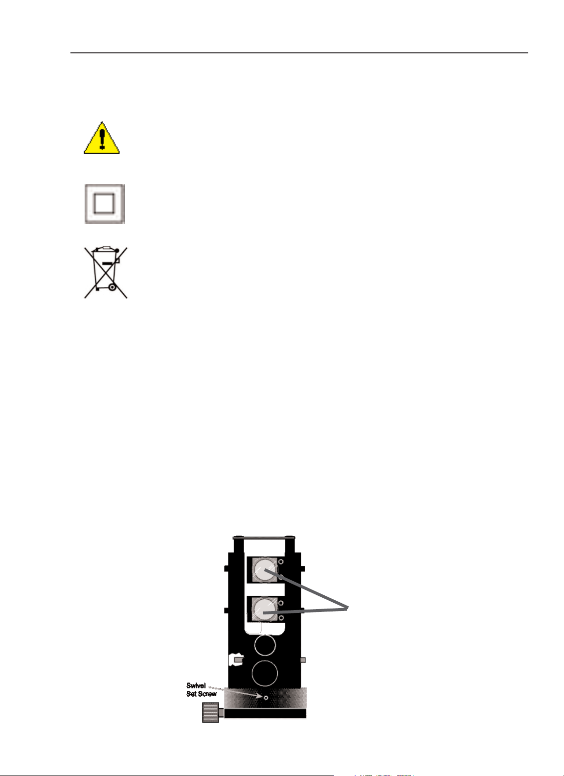
Definitions
Symbols
Indicates user to consult accompanying document
General Safety
Signal words are used according to international standards.
The meanings of these signal words are:
DANGER
- Indicates an imminently hazardous situation which, if not avoided,
will result in death or serious injury. This signal word is to be limited to the
most extreme situations.
WARNING
- Indicates a potentially hazardous situation which, if not avoided,
could result in death or serious injury.
CAUTION
- Indicates a potentially hazardous situation which, if not avoided,
may result in minor or moderate injury. It may also be used to alert against
unsafe practices. Permitted for property damage only accidents.
2
FOCUS - Remote Control (Red) Diode Laser
Introduction
(safety) Class II equipment
This symbol indicates that when the end-user
wishes to discard this product, it must be sent to a
separate collection facilities for recovery and
recycling.
Laser
Apertures

3
Installation and User Guide
Introduction
LASER SAFETY
WARNING
- Risk of incorrect diagnosis or treatment. Isocenter of alignment lasers
must coincide with isocenter of diagnostic or treatment equipment. Test alignment of
lasers before use daily for first month of operation and weekly after first month. Newly
installed equipment will shift as building walls and floor settle and as building
materials dry out. Realign lasers to isocenter before use, if they have moved.
CAUTION
- Laser Light, risk of eye damage.
• To prevent eye damage, do not stare into beam and do not allow patients to stare
into beam. The normal blink reflex will prevent eye damage. If a patient is unable
to blink normally the laser operator must prevent laser from shining in patient's eye.
Laser is a class II laser.
• Replace laser diode only with assembly provided by Gammex to ensure that laser
power levels do not exceed class II limits.
• Do not adjust sealed potentiometers as power levels could exceed class II limits and
damage the laser diode.
GENERAL
•
Sagittal laser
- Single vertical line projecting laser
•
Crosshair laser
- Crossed line projected from laser
•
Iso-center
- Center point where the X, Y, and Z planes coincide.
Storage and Transportation
• Do not drop
• Non-corrosive environment
• Storage Temperature: -20 - +75° C (-4 -167° F)
• Storage Humidity: 0 - 85% Relative Humidity (no dew condensation)
Environmental Limits:
• Temperature: 0-60° C (32 -140° F)
• Humidity: 0 - 85 % relative humidity (no dew or condensation)
• No flammable anesthetics
• No corrosives
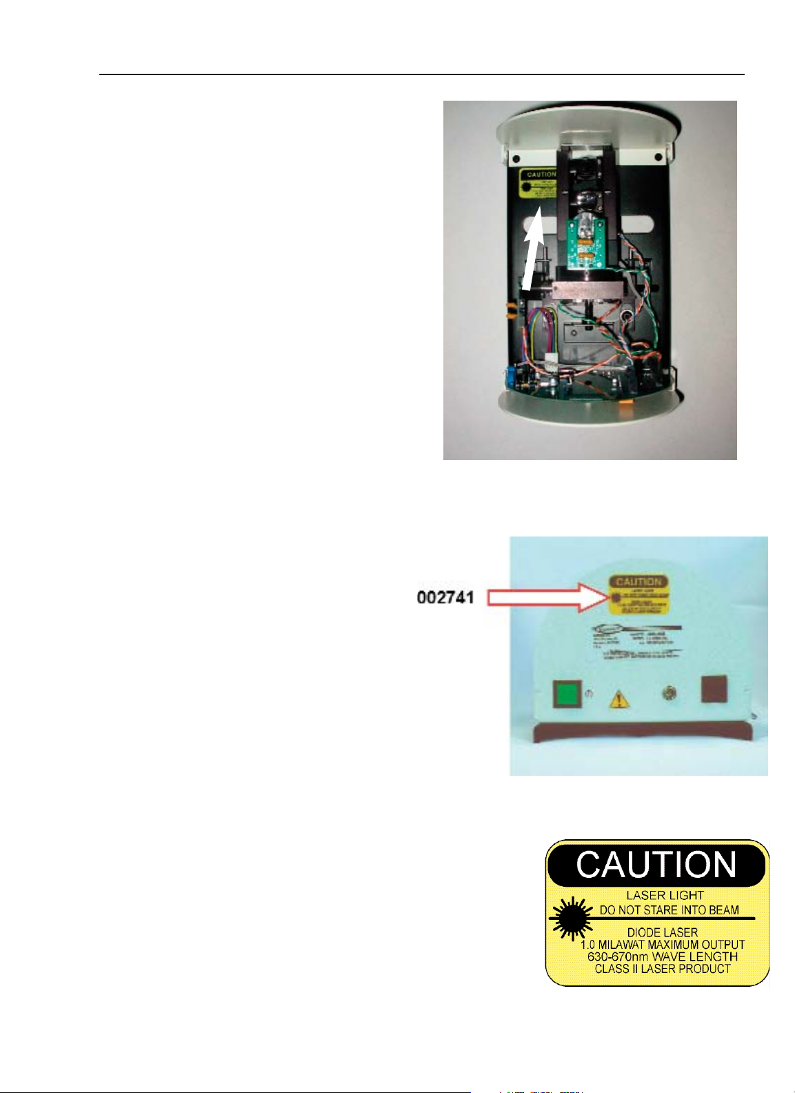
Location of Labels
Safety labels are located in two places on
the laser:
1. inside on the laser baseplate.
2. bottom outside of housing
002741 DECAL/CAUTION CLASS II DIODE LASER
Focus - Remote Control (Red) Diode Laser
Location of Labels
4
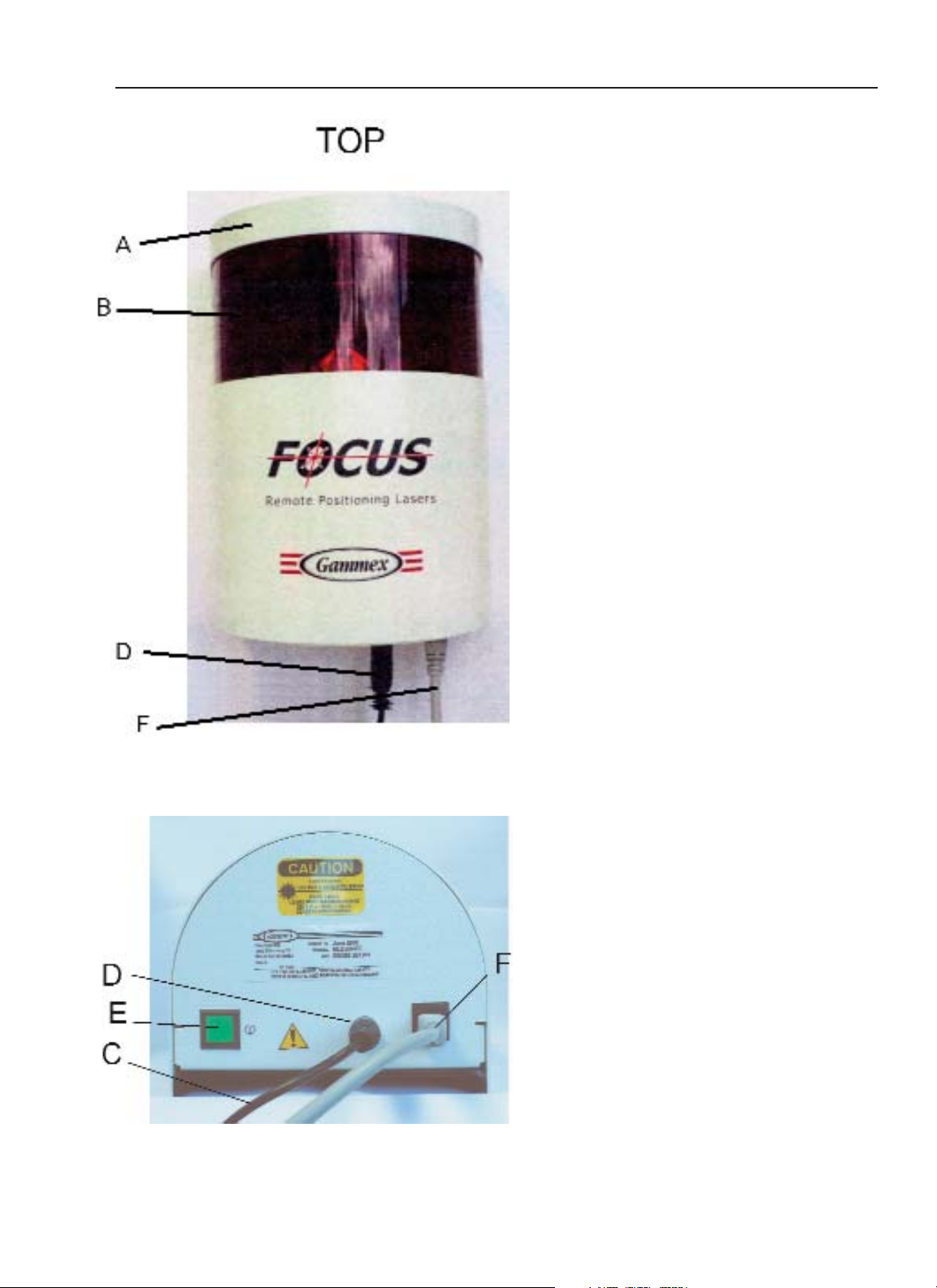
Operator Controls
A - Cover
B - Red Mylar Window
C - Power Supply Cord
D - Screw-on Power Plug
E - ON/OFF Switch (Push on/push off)
Lighted when on.
F - Remote Control Cable
• To turn the laser on: push the
ON/OFF button (E). The switch (E) will glow
green and you will see the beam of the red
laser on the window (B).
• To turn the laser off: push the On/Off
switch (E).The switch goes dark.
• Some facilities like to connect all the
lasers to one wall switch so all lasers
can be turned on and off from a
convenient location.
• Some facilities connect the lasers to a
timer so the lasers are automatically
turned off.
CAUTION - Use of controls or adjustments or
performance of procedures other than those
specified herein may result in hazardous
raditation exposure.
Operator Controls
Installation and User Guide
5
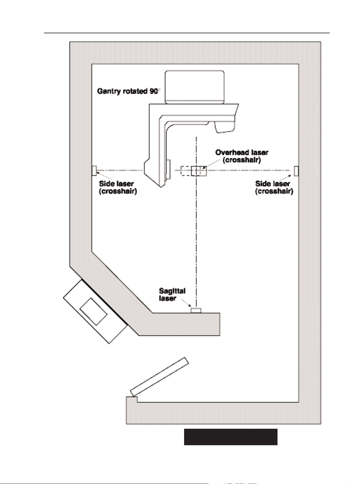
Figure 1
Pre-Installation
Focus - Remote Control (Red) Diode Laser
6

I
ntroduction
GENERAL
All Gammex FOCUS - REMOTE CONTROL (Red) Laser Alignment
Systems provide an optical aid for rapid and accurate patient positioning
and repositioning for therapy and simulator machines.
TECHNICAL DESCRIPTION
Various combinations of the GLD-450-RC crosshair FOCUS - REMOTE
CONTROL (Red) and the GLD-250-RC sagittal (straight line) FOCUS REMOTE CONTROL (Red) are used with different systems. The GLD-
450-RC lasers, mounted on each side, beam crosshairs along the Xaxis. The crosshair GLD-450-RC laser, mounted on the ceiling, beams a
crosshair vertically along the Z-axis. The sagittal GLD-250-RC laser
beams a straight line in the Z-Y plane.
Installation Requirements
ELECTRICAL
Each laser is provided with a universal power supply (transformer) with
an input of 100 to 240 volts at 50 to 60 Hz. The universal power supply
plugs into a wall outlet with 4 interchangeable “snap-in” plugs to fit most
outlets. A 1.2 meter (4 foot) power cord supplies 12 volt dc power to the
laser with a screw-on power plug
TOOLS NEEDED
In addition to some basic tools, such as screwdrivers, hammer and
ladder; you will need an electric hammer drill, plumb bob, level, water
level, masking tape and 15M (50 feet) of string. (The mounting
hardware, a 1/4-20 tap and tap drill, and 4 hex (Allen) wrenches (.050”,
1/8”, 3/32”, & 5/64”) are included with the lasers.)
CAUTION: The location of the lasers is determined in relation to the
therapy machine’s crosshair and isocenter. Before installing lasers, ask
the physicist to verify that the field light aligns with the machine’s
isocenter. Figure 1.
Pre-Installation
Installation and User Guide
7
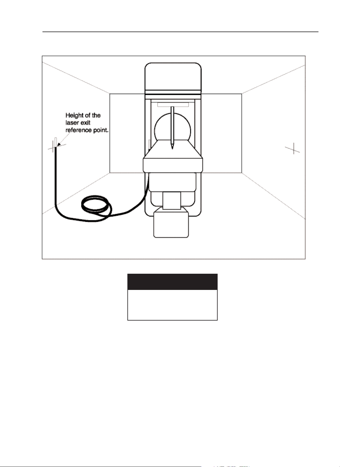
Figure 2
Use a water level to line up
the laser exit reference point
at the height of isocenter.
Pre-Installation
Focus - Remote Control (Red) Diode Laser
8
Pre-Installation
Use a water level, see Fig. 2, to line up the laser exit reference
point at the height of isocenter.
PREPARING THE ROOM
1. Unpack each laser, add the cord and plug into a wall outlet.
2. Turn the linear accelerator lamp on.
3. Set gantry and collimator to 0° and level the collimator.
4. Lower the table as low as possible.
COLLIMATOR CROSSHAIR ACCURACY
The collimator-projected crosshair is used as a reference
when determining the laser locations. The light field should
coincide with isocenter, the gantry should be level and, if
collimator crosshair displacement exists, it should be
compensated for.
1. Project a crosshair onto a piece of paper taped to the table
and mark the center with a dot.
2. Rotate through 360° and mark the center again.
3. If there is a difference between the two dots, find the
center of the distance between the two dots. Mark this
point and use this point as the crosshair center reference
point. Use this point to line up the laser.
USING THE WATER LEVEL
Use a water level, see Fig. 2, to determine the height of the
laser exit reference point when installing lasers in a simulator
room or in a room with angled walls. In standard treatment
rooms, the water level should also be used to verify the laser
location.
1. Raise the table to the front pointer (isocenter).
2. Remove caps on ends of water level and remove air
bubbles.
3. Line up with the table edge and with the wall.
Figure 2
4. The water line on the wall indicates the horizontal axis of
the laser exit reference point.
Use a level to verify:
• Gantry is level each time
it is rotated
• Template is placed
accurately on wall
• Crosshairs on wall are
at 90° angles
Pre-Installation
Installation and User Guide
9

Figure 3
Rotate the gantry
90° and project
a crosshair onto
the wall.
Figure 4
Use a string to
verify the location
of the side lasers.
Side Laser Installation
Focus - Remote Control (Red) Diode Laser
10
Installing Lasers
SIDE LASER INSTALLATION
For all GLD-450-RC (crosshair) installations.
For angled walls, refer to page 35.
1. Rotate the gantry 90° to the 270° position and project
a crosshair onto the wall.
Figure 3
2. Use a pencil and straight rule to trace the crosshair
onto the wall.
3. Line up the template from page 56, so that the
projected crosshair lines up with the laser exit point on
the template. Use a level to line up the template.
4. Mark the outer edge of the template and also mark the
mounting holes.
5. Rotate the gantry 180° to the 90° position and repeat
steps 2-4 on the opposite wall.
6. Return the gantry to 0°.
7. Tape a piece of paper to the table.
8. Project a crosshair onto the paper, keep the field as
wide as possible.
9. Hold the ends of a plumb bob on each wall until string
shadow is in line with projected crosshair.
Figure 4
10. The point at which the string hits the wall is the center
of the laser exit point. Mark the center on the wall.
Use the template to verify the location of the mounting
holes.
11. Drill the mounting holes.
12. Remove the FOCUS - REMOTE CONTROL (Red)
from its carton. Remove two screws at the top of the
cover using a 5/64” hex (Allen) wrench. Slide the
cover up, to disengage it, and lift the cover out.
Remove the packing support from the optics and
remove the plastic tie from around the optics.
Use a level to verify:
• Gantry is level each time
it is rotated
• Template is placed
accurately on wall
• Crosshairs on wall are
at 90° angles
Side Laser Installation
Installation and User Guide
11

Figure 5
Mount the base
plate to the wall
with the supplied
mounting hardware.
Use the template
to indicate where
on the wall to
mount the laser.
A: Exit Reference
B: Base Plate
C: Laser Assembly
D: End Plate
E: Main body cover
F: Mounting Screws
G: Washers
H: Wall Anchors (Masonry)
Use 3/8" drill
I: Mounting Spacers
Side Laser Installation
Focus - Remote Control (Red) Diode Laser
12

Installing Lasers
SIDE LASER INSTALLATION (continued)
13. Attach washers and screws with mounting spacers as
shown in
Figure 5
. Mount the laser to the wall Figure 5.
Laser must be firmly mounted. Oversized holes provide
flexibility to line up the exit reference, Use suitable
anchors. Wall anchors for masonry are provided in the
mounting kit.
Use a 3/8” diameter drill for the provided anchors.
14. Do not replace the cover at this time.
15. Plug in the universal power supply. Attach the threaded
power plug to the bottom of the laser. Turn on the laser.
The push switch will toggle on and off. The switch should
light and the laser lines project.
16. Plug in the remote control receiver.
17. Rotate the gantry 90° (so that the crosshair is projected
onto the laser) and tape a piece of paper to the gantry
head, covering the projected light field.
18. Adjust the laser so that the laser crosshair lines up with
the collimator cross hair. Refer to the following pages for
the methods for making laser adjustments.
19. Place a piece of paper directly in front of the laser.
20. Verify that the center of the projected collimator crosshair
is centered on the top laser lens.
21. Adjust for straight lines if necessary.
Refer to the following pages.
22. Turn off the laser.
23. Place the cover on the laser. Slide it downward to
engage the pins, then replace the screws at the top of
the cover. Take care not to jolt or bang the laser.
24. Check the alignment of the laser several times. Use the
remote control for minor adjustments.
25. Return the gantry to 0°.
Side Laser Installation
Installation and User Guide
13
Remote Control
Remote control is a radio communication feature that allows the operator to align as
many as five lasers with one hand-held controller. Each Focus laser has a separate wall
mounted receiver that communicates with the operator's transmitter. The receivers and
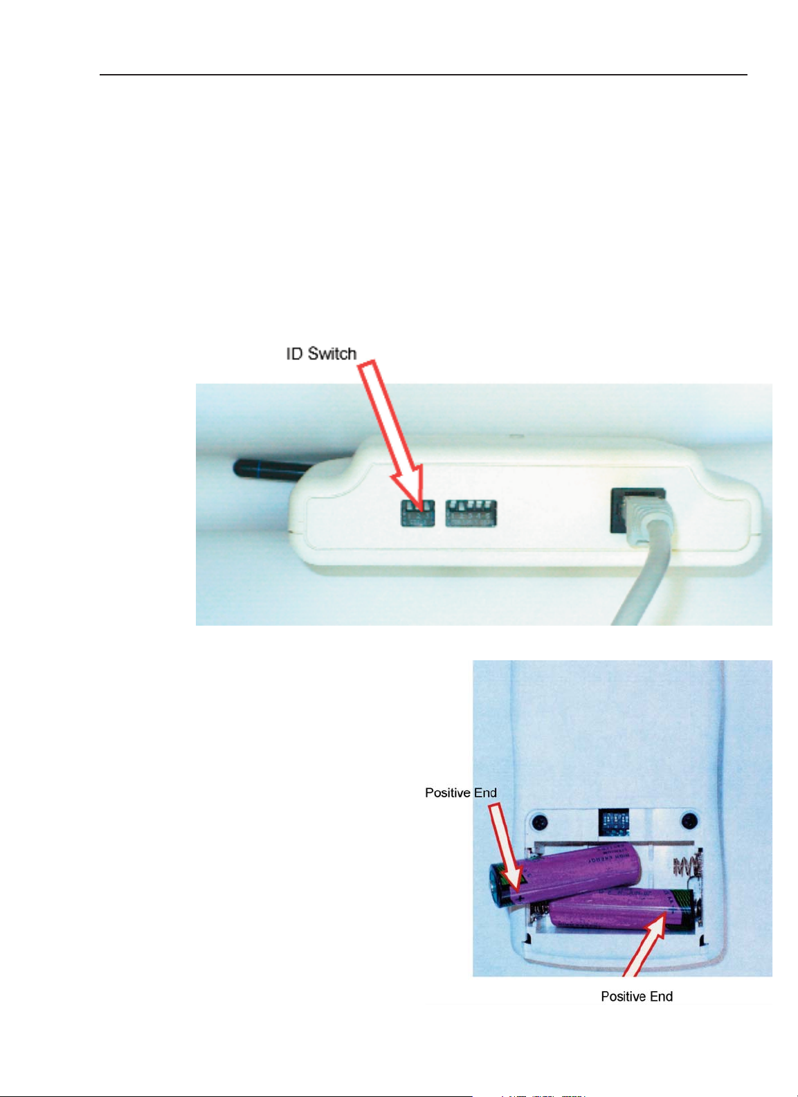
transmitter all have an ID switch. The ID switch sets the identification number for the
system. This allows different rooms to operate remote control lasers in close proximity
without interference. All remote control receivers in a room will have the same ID
number. Different rooms will have different ID numbers. To communicate properly, the
transmitter ID must be set to match the receiver IDs of all of the laser receivers in a
system.
SETTING THE TRANSMITTER ID
The transmitter ID switch is accessible
through the battery compartment. To set
transmitter identification, remove the
battery cover and locate the switch. It will
have three small toggles labeled 1, 2, and
3. Each toggle has an "on" position and
an "off" position. For ID one, set switch 1
"on" and all other switches "off". For ID
two, set switch 2 "on" and all other
switches "off". ID three has 1 and 2 "on"
and 3 "off". ID four has 3 "on" and all other
switches "off". This sequence can continue
up to ID seven which has all switches "on".
The following table gives all of the
combinations.
Operator Controls
Focus - Remote Control (Red) Diode Laser
14
ID SWITCH 1 SWITCH 2 SWITCH 3
0 OFF OFF OFF
1 ON OFF OFF
2 OFF ON OFF
3 ON ON OFF
4 OFF OFF ON
5 ON OFF ON
6 OFF ON ON
7 ON ON ON
Operator Controls
Installation and User Guide
15
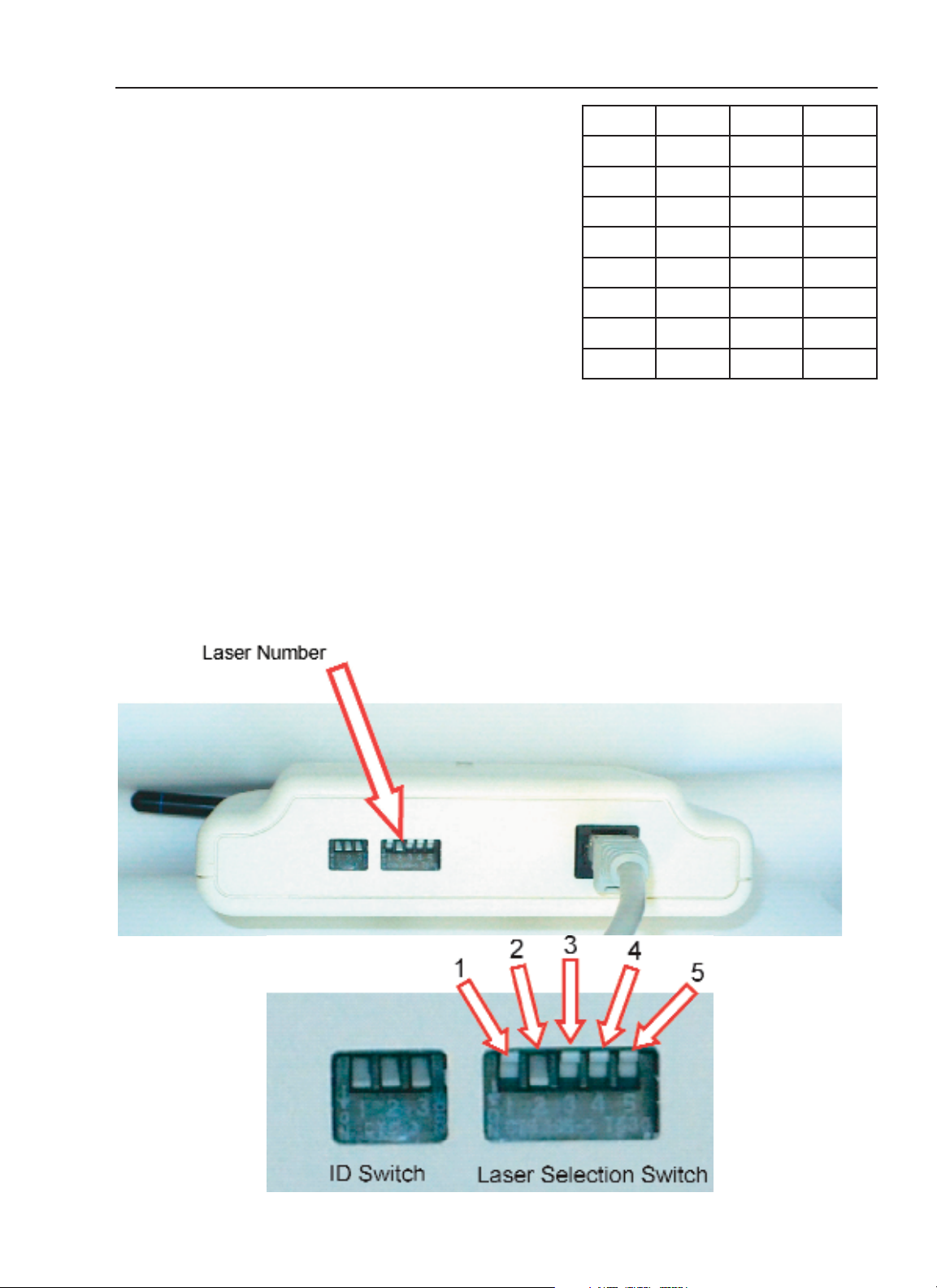
SETTING THE RECEIVER LASER NUMBER
The other switch on the bottom of the receiver selects the number for the laser. This
corresponds directly to the laser number selection on the hand held transmitter.
Each receiver has a switch with five positions. These positions represent the number of the
laser that the receiver controls. If we move the first lever down and the rest up, then that makes
the receiver number one, and the laser connected to it is also number one. The second lever
stands for number two, and the third lever stands for number three. Only one lever may be in
the down position for any given receiver. The other four switch levers must be up.
Verify that the ID switch settings on all receivers in a
system match the transmitter id switch setting.
16
FOCUS - Remote Control (Red) Diode Laser
Laser Positioning Adjustments
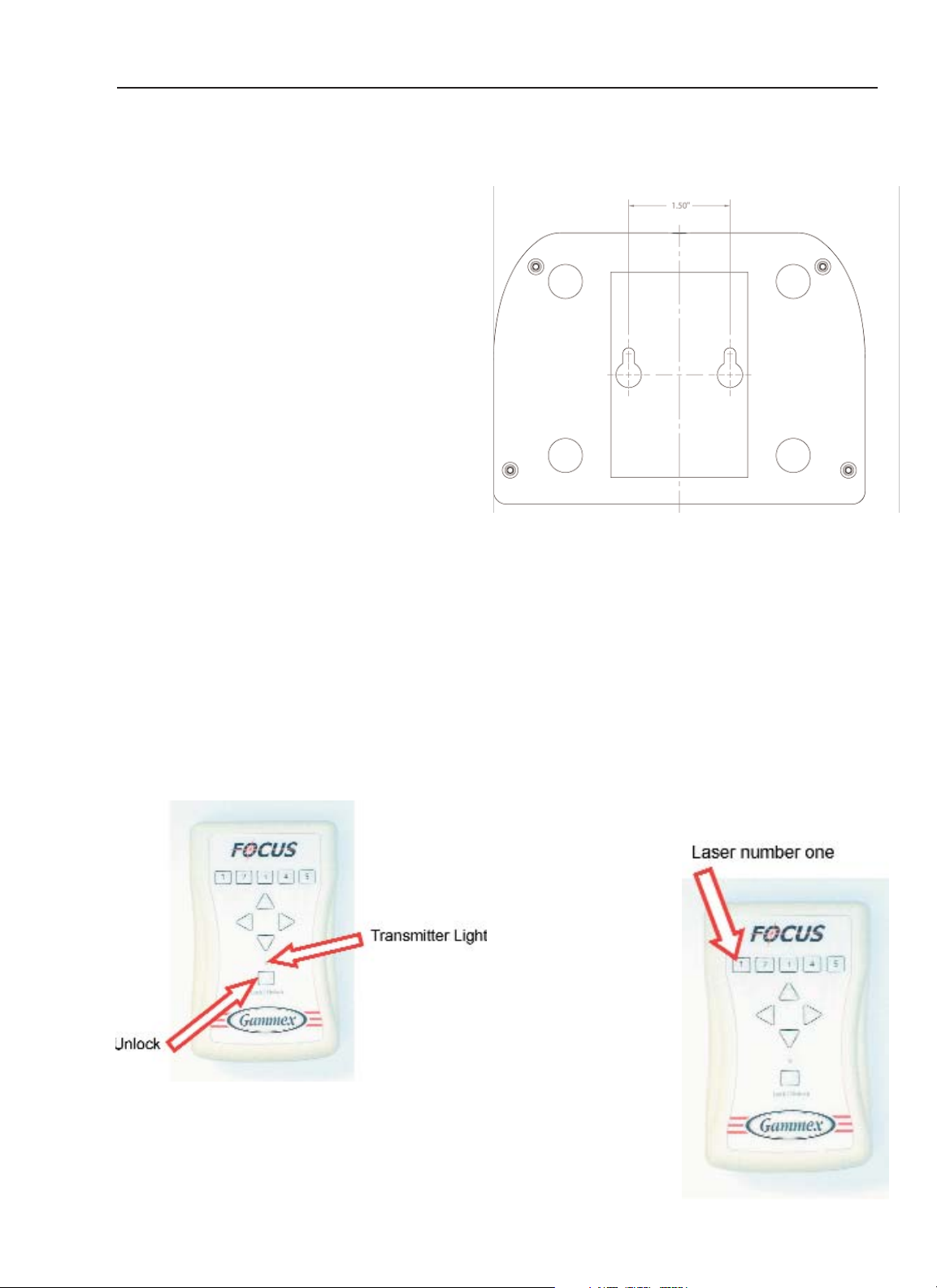
To Align the lasers using the Remote
Control
1. Plug in the receiver if they are not
already connected.
2. Push the unlock button to activate
the transmitter. The transmitter light
should turn on.
3. On the transmitter, select the
number of the laser that you
wish to align.
The remote control receivers can be
mounted to a wall, ceiling or other
appropriate surface using two #8
screws (not included), spaced 1.5”
apart. Keyhole slots in the back of the
receivers will then fit over the screw
heads and hold the receivers in place.
The receivers can be damaged by
radiation and should therefore be
mounted outside of the radiation field.
Once mounted, connect each receiver
to its corresponding laser with the
included cable.
The remote control transmitter can be
damaged by radiation and should not
be left in the radiation field.
17
Installation and User Guide
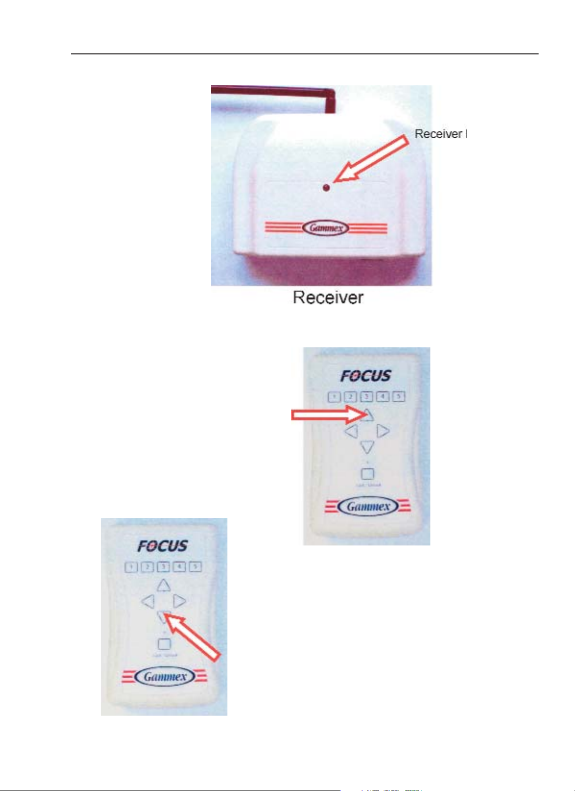
Laser Positioning Adjustments
5. Move the laser line
to its correct position.
This button moves the laser
line upward or toward the
head
This button moves the laser
beam downward or toward the
feet
4. The corresponding
receiver light should
come on.
 Loading...