

Gamma X-Stringer XLT Owner's Manual

XLT
ELECTRONIC
STRINGING MACHINE
OWNER’S MANUAL
Issue 1 - September 2018

XLT
OWNER’S MANUAL
TABLE OF CONTENTS
WARRANTY ................................................................................................ PAGE 2
KEY FEATURES ......................................................................................... PAGE 3
ASSEMBLY INSTRUCTIONS ..................................................................... PAGE 4
POWER CONNECTION & CONTROLS ..................................................... PAGE 6
MOUNTING THE FRAME ........................................................................... PAGE 9
STRINGING THE FRAME .........................................................................PAGE 10
ADDITIONAL FEATURES ......................................................................... PAGE 13
PATHFINDER AWL .................................................................................... PAGE 14
MAINTENANCE & ADJUSTMENTS ......................................................... PAGE 15
TROUBLESHOOTING TIPS ..................................................................... PAGE 17
PARTS LIST ............................................................................................. PAGE 18
PARTS DRAWING..................................................................................... PAGE 19
LIMITED WARRANTY
GAMMA Sports (GAMMA) warrants to the original purchaser that the XLT stringing machine (“EQUIPMENT”) purchased is
free from defects in materials and workmanship for a period of fi ve (5) years from the date of original purchase for mechanical parts and for a period of one (1) year from the date of purchase for all electrical parts and string clamps. Should any
defects develop under normal use within the specifi ed time periods, GAMMA will at its option, repair or replace the defective
EQUIPMENT provided it is returned to GAMMA prepaid at the purchaser’s expense. This warranty does not apply to any
damage or defect caused by negligence, abuse, misuse, unauthorized alteration, shipping, handling, or part wear and tear
as a result of normal use.
Routine maintenance, adjustment, and cleaning required to ensure proper operation are the responsibility of the purchaser and
are not covered under the terms of this warranty. These include, but are not limited to: String Clamp adjustment, as described
on page 16, Quick Action Clamp Base adjustment, as described on page 16 and the cleaning procedures listed on page 16.
GAMMA’s obligation under this warranty is limited to repair or replacement of defective EQUIPMENT, and no one is authorized
to promise any other liability. GAMMA shall in no event be liable for any incidental or consequential damages.
To return defective EQUIPMENT, a return authorization (RA#) must be obtained from a GAMMA customer service representative. The RA# must be marked on the outside of the shipping carton being returned. All returns must be shipped prepaid by
the customer to GAMMA. Please retain the original shipping carton and packing materials for any future shipments. GAMMA
will not be responsible for machines which are not sent in the original undamaged packaging.
A GAMMA Care Service Plan is also available through GAMMA customer service, call 800.333.0337 for details.
2
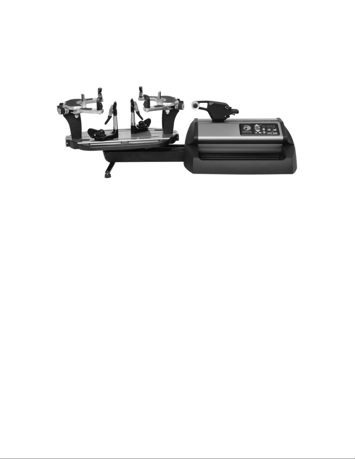
FEATURES
MACHINE FEATURES
Electric Constant Pull Tensioner with 11.0 to 90.0 lbs Tension
Range
Digital Tension Setting with LED Display
Parallel Jaw Linear Gripper with Textured Gripping Surfaces
Professional Six Point “Quick Mount” Racquet Mounting
System- Accommodates All Racquets
Professional “Quick Action” Dual Action, Rotating String Clamp
Bases
5 Tooth, Universal String Clamps with Textured Gripping
Surfaces
High Strength Extruded Aluminum Base with Durable Anodized
Finish
Large (Removable) Padded Tool Tray
3
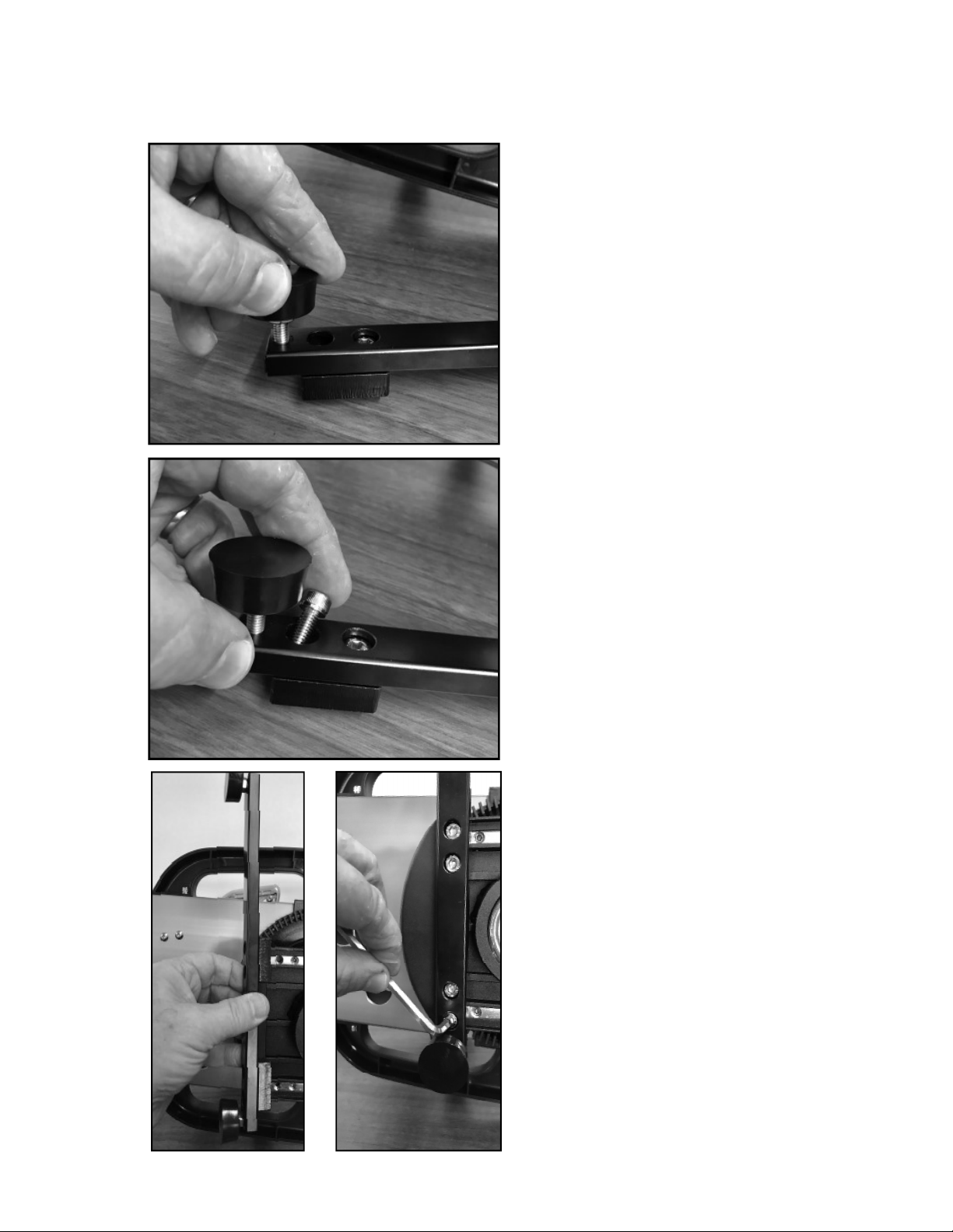
ASSEMBLY INSTRUCTIONS
Leg Bracket with Foot Pads
There are four rubber foot pads supplied
with the machine. Two have exposed
threads and two have a spacer sleeve
over the threads. Install the two rubber
foot pads with the exposed threads into
the outer holes on both ends of the leg
bracket.
Mounting the Leg Bracket
Insert two hex head cap screws to the
holes next to the rubber foot pad.
Mounting the Leg Bracket
Attached the leg bracket on the left side
of the base by aligning the holes in the
leg bracket with the threaded holes in
the rails located on the underside of the
machine base as shown. Tighten the hex
head bolts.
NOTE: If desirted, the Leg Bracket may
also be installed on the right side of
the base. If this position is desireable,
the Tool Tray must be installed prior
to installing the Leg Bracket.
4
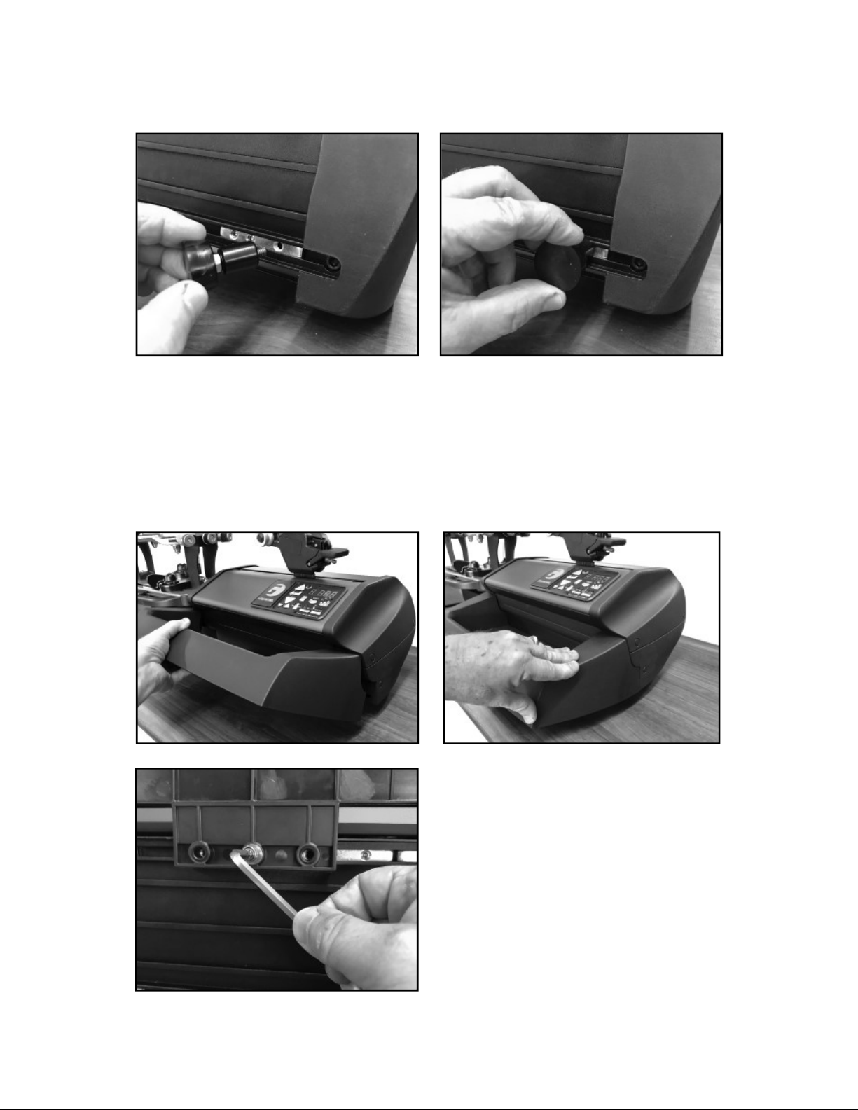
ASSEMBLY INSTRUCTIONS
Rubber Foot Pad Installation
Insert the two rubber foot pads with the spacer sleeve into the into the threaded holes of the
rails located on the underside of the baser on the right side as shown.
NOTE: If desirted, the Rubber Foot Pads may also be installed on the left side of the
machine base.
Installing the Tool Tray
Hold the tool tray on an angle and align the tabs
on the tool tray with the slots in the machine
base. Rotate the tool tray down and apply
pressure until the tool tray “snaps” into place.
Secure the tool tray with three bolts in the
bottom of the machine base from underneath.
Reverse the steps above to remove the tool
tray for ease of travel.
NOTE: If the Leg Bracket is installed on
the right side of the base, the Tool Tray
must be installed prior to installing the
Leg Bracket.
5
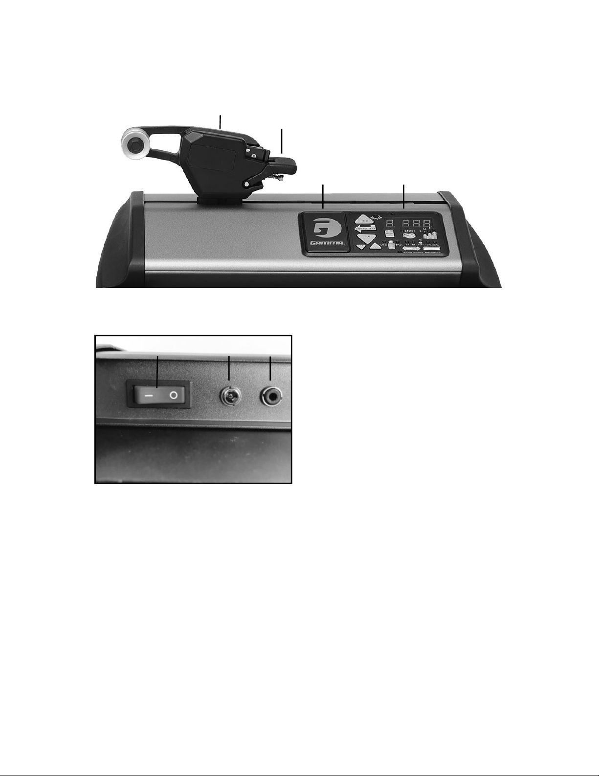
POWER CONNECTION & CONTROLS
Front Panel Features
A
A C
B
A - String Gripper
B
B - Tension Lever
C - Control Panel
D - LED Display
C
Back Panel Features
A - Power On/Off Switch
B - A/C Power Cord Socket
D
C - Foot Pedal Switch Receptacle
Instructions for Power Connection and Controls
CAUTION ! Before connecting to the power supply, check the voltage source that the
machine is being connected to. The acceptable range of input voltages for this machine is between 100 V and 240 V @ 50 to 60 Hz. If you have any questions regarding
the input voltage supply for your area, please ask your electric utility company.
To install the power cord, insert the female end of the power cord into the AC Adapter and
then insert the female end of the cord from the AC Adapter into the A/C Power Cord Socket
“B” located on the back panel of the tensioner. Plug the male end of the power cord into a
grounded power outlet. When using extension cords, use grounded heavy duty extension
cords rated for 15 AMP service.
To connect the foot pedal switch, insert the male pin at the end of the foot pedal switch cord
into the Foot Pedal Switch Receptacle “C” located on the back panel of the tensioner.
Switch on the machine by pressing the Lighted On-Off Power Switch on the back panel. At
start-up, the LED will display a countdown from “9.0” to “0.0” while the machine performs a
self diagnostics check at start-up.
6
 Loading...