

Page 1

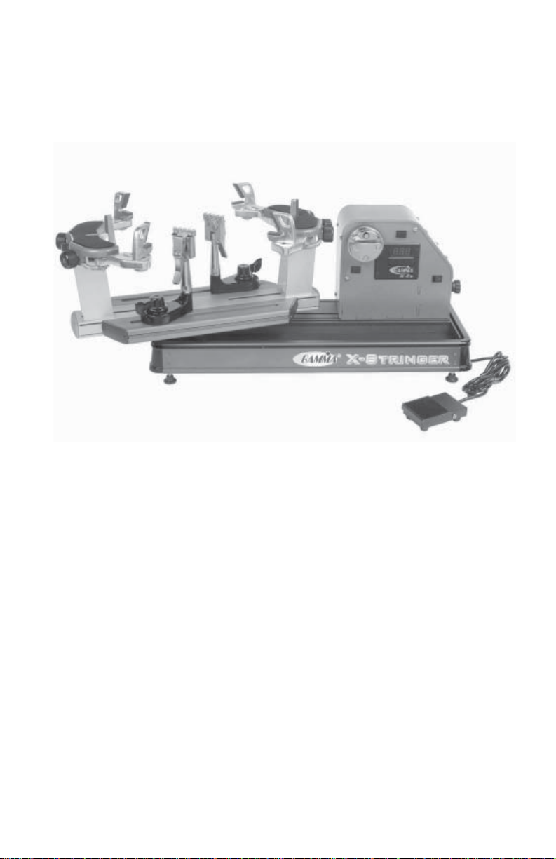
X-ES
STRINGING MACHINE
OWNER'S MANUAL
Issue 1 - May 2004
Copyright 2004 GAMMA Sports - All Rights Reserved
Page 2

OWNER'S MANUAL
GAMMA X-ESGAMMA X-ES
GAMMA X-ES
GAMMA X-ESGAMMA X-ES
TABLE OF CONTENTS
PAGE 1 ................................................................................................ WARRANTY
PAGE 2 ................................................................................................. FEATURES
PAGE 3 ..................................................................... ASSEMBLY INSTRUCTIONS
PAGE 5 .................................................... POWER CONNECTION & CONTROLS
PAGE 6 ........................................................................... MOUNTING THE FRAME
PAGE 8 .......................................................................... STRINGING THE FRAME
PAGE 11 ........................................................................ ADDITIONAL FEATURES
PAGE 12 .................................................................................. PATHFINDER AWL
PAGE 13 ................................................... MAINTENANCE AND ADJUSTMENTS
PAGE 15 ..................................................................... TROUBLESHOOTING TIPS
PAGE 17 ............................................................................................. PARTS LIST
PAGE 18 .................................................................................... PARTS DRAWING
LIMITED WARRANTY
GAMMA Sports (GAMMA) warrants to the original purchaser that the X-STRINGER stringing machine ("EQUIPMENT")
purchased is free from defects in materials and workmanship for a period of five (5) years from the date of original purchase
for mechanical parts (excluding electrical parts and string clamps), and for a period of one (1) year from the date of purchase
for all electrical parts and string clamps. Should any defects develop under normal use within the specified time periods,
GAMMA will at its option, repair or replace the defective EQUIPMENT provided it is returned to GAMMA prepaid at the
purchaser's expense. This warranty does not apply to any damage or defect caused by negligence, abuse, misuse,
unauthorized alteration, shipping, handling, or part wear and tear as a result of normal use.
Routine maintenance, adjustment, and cleaning required to ensure proper operation are the responsibility of the purchaser
and are not covered under the terms of this warranty. These include, but are not limited to: String Clamp adjustment, as
described on page 11, Quick Action Clamp Base adjustment, as described on page 11, and the cleaning procedures listed
on page 13.
GAMMA's obligation under this warranty is limited to repair or replacement of defective EQUIPMENT, and no one is authorized
to promise any other liability. GAMMA shall in no event be liable for any incidental or consequential damages.
To return defective EQUIPMENT, a return authorization (RA#) must be obtained from a GAMMA customer service
representative. The RA# must be marked on the outside of the shipping carton being returned. All returns must be shipped
prepaid by the customer to GAMMA. Please retain the original shipping carton and packing materials for any future shipments.
GAMMA will not be responsible for machines which are not sent in the original undamaged packaging.
1
Page 3
GAMMA X-ESGAMMA X-ES
GAMMA X-ES
GAMMA X-ESGAMMA X-ES
MACHINE FEATURES
MACHINE FEA TURES
Electric Constant Pull Tensioner w/ 11 lb. to 89 lb. Tension
Range
Digital Tension Setting Display
Professional Six Point “Quick Mount” Racquet Mounting
System - Accomodates All Racquets Without Adapters
Parallel Jaw Rotating Gripper w/ Diamond Dust Coated
Gripping Surfaces
Professional Dual Action, Rotating, Diamond Dust Coated,
Fixed String Clamps
High Strength Extruded Aluminum Frame with Durable
Anodized Finish and Convenient Padded Tool Tray
Unique Internal Drawer System for Storing Tools and Adap-
tors.
Convenient Foot Actuated Tensioner Switch
2
Page 4
ASSEMBLY INSTRUCTIONS
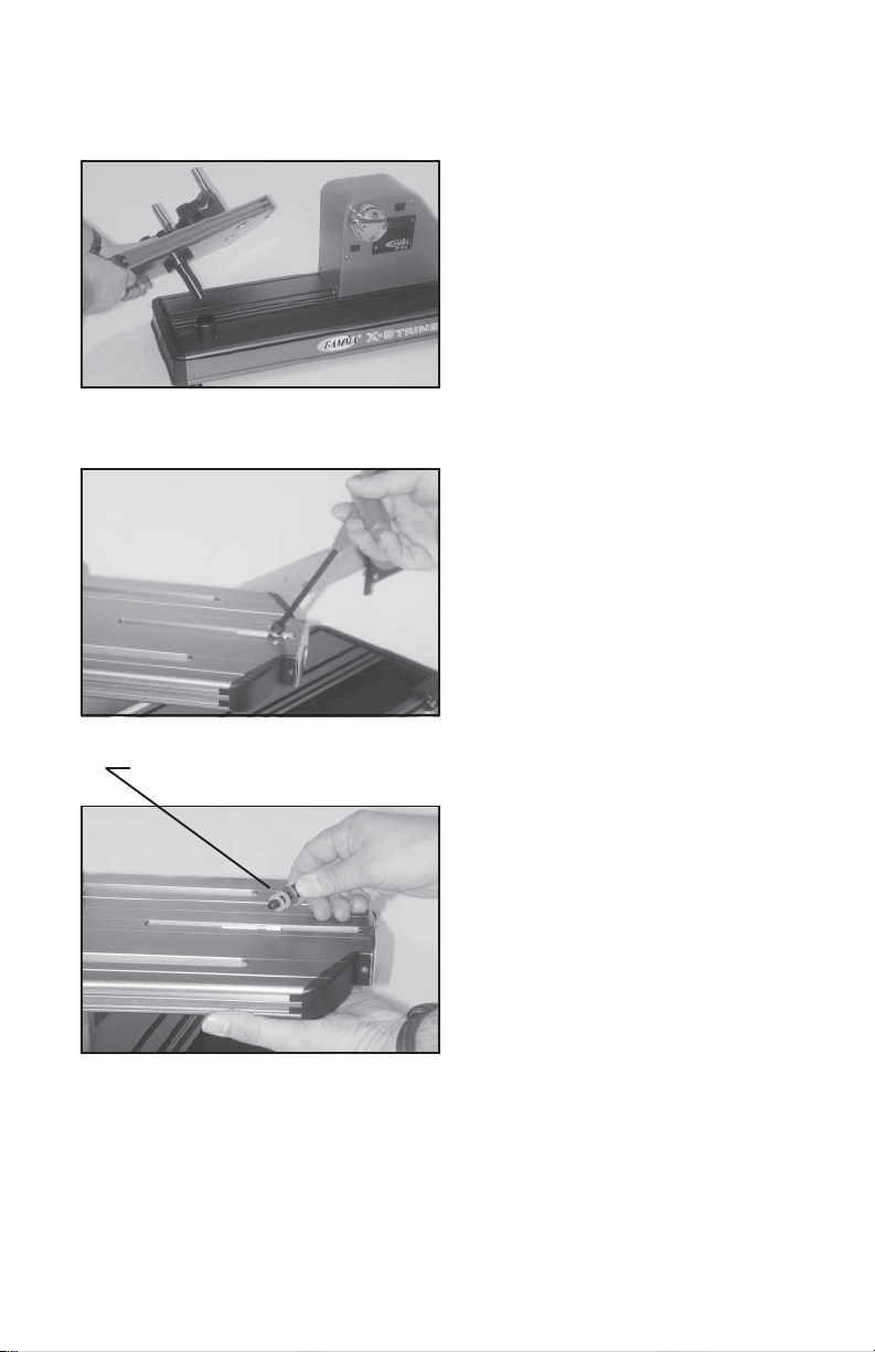
Turntable Installation
Insert the turntable pin into the bushing of
the machine base.
Support Post Installation
To install the support posts you must first
remove the mounting bolt from the mounting
plate that sets inside the central cavity of the
turntable. There are large holes stamped on
the underside of the turntable that allow you
to support the mounting plate with your
fingers while removing the mounting bolt.
Remove and Discard Plastic Washers
Support Post Installation (con’t)
After removing the mounting bolt, remove
and discard the plastic washers that are
installed for shipping purposes.
3
Page 5
ASSEMBLY INSTRUCTIONS
Support Post Installation (cont’d)
Place the support post onto the central slot
of the turntable. With your fingers placed
through the large hole in the underside of the
turntable, press the mounting plate against
the inside top surface of the turntable while
aligning the hole in the support post with the
hole in the mounting plate and fix them with
the mounting bolt. Repeat procedure on to
attach the support post on the opposite side
of the turntable.
String Clamp Installation
The post of the string clamp and tube of the
string clamp base are treated with grease to
provide protection against corrosion during
shipping. Remove any excessive grease
with a clean cloth prior to use. The post and
tube may also be cleaned with isopropyl
alcohol. After this type of thorough cleaning,
the post and tube should be treated with a
light coating of machine oil to protect the
surfaces against corrosion and to ensure
smooth operation.
4
Page 6
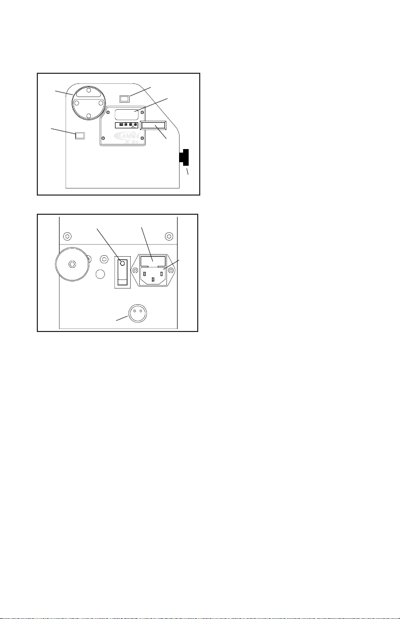
POWER CONNECTION & CONTROLS
A
F
A
D
B
C
E
B
A - String Gripper
B - Tension Switch
C - L.E.D. Tension Display
D - Tension Adjustment Knob
E - Calibration Screw Cover Plate
F - Gripper Reversing Switch
D
Side Panel Features
A - Lighted Power Switch
To turn the power on, press the left
C
side of the switch.
B - 5 Amp Fuse Holder (w/ spare fuse)
C - A/C Power Cord Socket
D - 2 Pin Foot Pedal Switch Receptacle
Instructions for Power Connection and Controls
CAUTION ! Before connecting to the power supply, check the voltage supply switch
located on the back side of the tensioner. To change from 110 to 220 volt service
slide the switch fully to the left or to the right until “115V” or “230V” appears on the
switch plate.
Front Panel Features
The acceptable range of input voltages for the “115 V” setting is between 110 V and 120 V
@ 60 Hz and for the “230 V” setting, between 220 V and 240 V @ 50 to 60 Hz. If you have
any question regarding the input voltage supply for your area, please ask your electric
utility company. When using extension cords, use grounded heavy duty extension cords
rated for 15 AMP service.
To install the power cord, insert the female end of the power cord into the Power Cord
Socket located on the rear panel (letter C). To connect the foot pedal switch, insert the 2
pin male connector located at the end of the foot pedal switch cord into the two pin
receptacle located on the back panel. Tighten the connector with the sleeve nut located on
the foot pedal switch connector.
After checking to be certain that the machine is set for the correct input volt age, switch on
the machine by pressing the Lighted On-Off Power Switch on the rear p anel.
WARNING! FOR INDOOR USE ONLY . TO BE USED
BY ADUL TS OR UNDER ADUL T SUPERVISION ONLY .
NEVER OPEN UNIT WITH POWER CONNECTED
5
Page 7

POWER CONNECTION & CONTROLS
Setting Tension
The stringing machine utilizes an adjustment knob along with a digital L.E.D. display to indicate the tension setting. To set
the tension, rotate the adjustment knob
clockwise to decrease the displayed tension and counter-clockwise to increase the
displayed tension, until the desired tension
is displayed. Aramid fiber and metallic
strings will generally string up tighter on the
X-ES machine compared to synthetic or
ing with Aramid (Kevlar, Technora) hybrid strings or metallic strings, we recommend setting
tension 4-5 lbs. lower than you would normally use for synthetic or natural gut strings.
natural gut strings. Therefore, when string-
MOUNTING THE FRAME
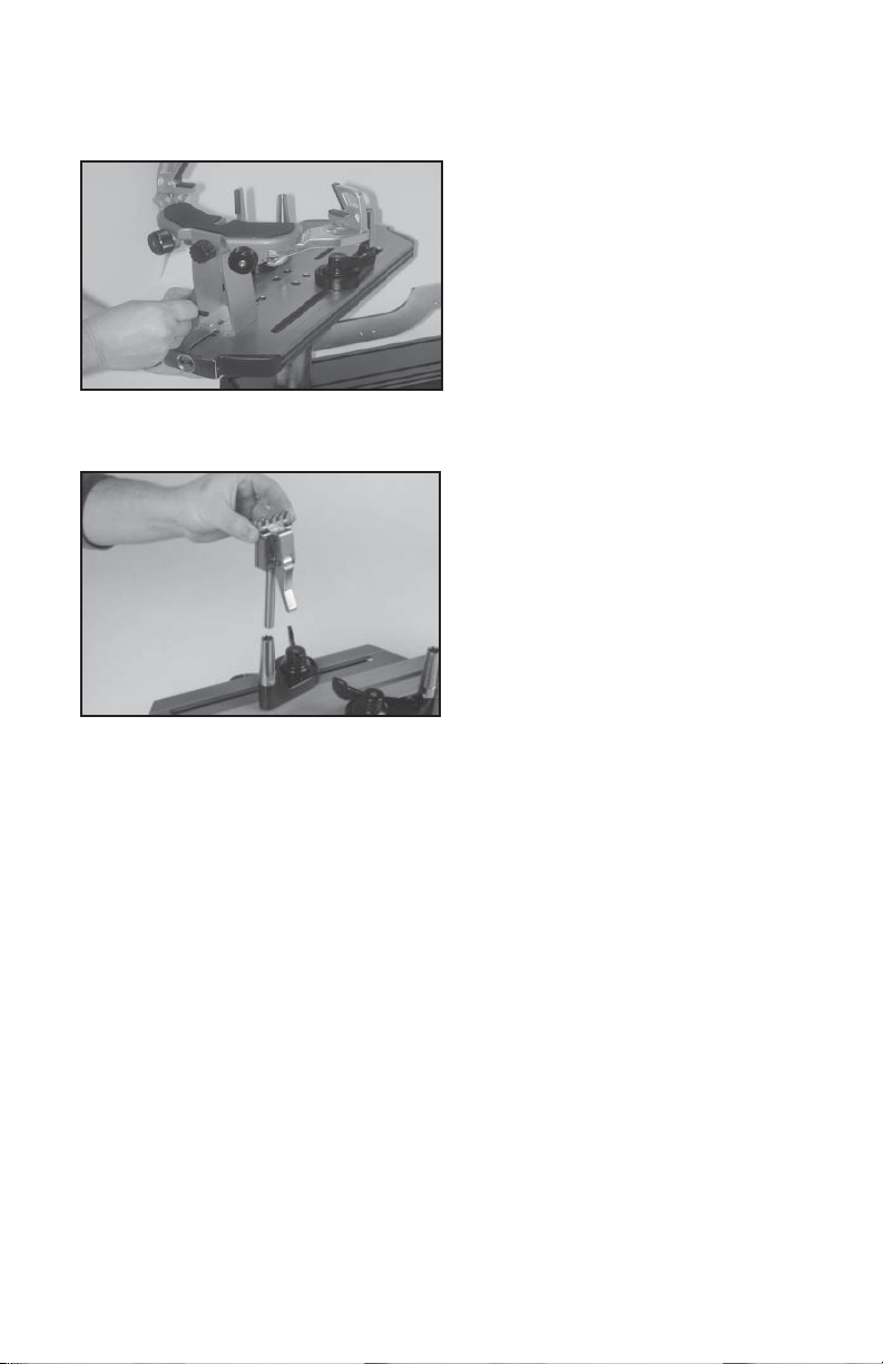
Adjusting the Frame Support Posts
Loosen the lock bolts of the frame support
posts and space them apart with the frame
support slides separated by the approximate length of the racquet head. Although it
is not required, it is good practice to center
the support posts on the turntable. Lock one
of the posts in position by tightening the lock
bolt and position the other post until the
frame support slide is positioned near the
inside surface of the racquet frame. Securely tighten the lock bolt of the second
support post.
Caution: To avoid racquet damage, the center posts should not contact the racquet prior to
locking down the support posts.
Tightening the Frame Supports
Tighten the Frame Support Slides by turning
the adjustment knob clockwise until snug
against the racquet frame and slight resistance is felt.
Caution: Overtightening the Center Supports will stretch the head of the racquet and
could cause racquet damage.
6
Page 8

MOUNTING THE FRAME
Frame Shoulder Support Adjustment
Being sure the shoulder supports are free to
swivel in their mountings, simultaneously
rotate the shoulder support adjustment knobs
clockwise until both shoulder supports gently and squarely contact the frame.
Securing the Frame Shoulder Clamps
Lock the shoulder supports in position by
turning the knob at the base clockwise.
Repeat the adjustment procedure for the
remaining support post.
Re-tighten all of the frame supports in the
same order as before.
Do not overtighten any of the supports as
racquet damage may occur.
The supports should be tightened to the
in the mounting system when the handle is grasped and attempts are made to move it. Should
any supports lose contact with the frame while stringing, they should be re-tightened.
point where the racquet frame will not move
7
Page 9

STRINGING THE FRAME
String Clamp Operation
The string clamps are a dual action design
where the string clamp and clamp base
operate independently of one another.
To clamp a string, lift the clamp head and
place the string between the jaws and depress the string clamp lever to secure the
string. The clamping pressure applied to the
string should be adjusted to provide sufficient pressure to secure the string when
subjected to the desired pulling tension. The
diamond coated gripper plates provide for
the string to allow for reduced clamping pressure while securing and holding the string under
tension.
increased friction between the clamps and
Clamp Base Operation
To lock the string clamp base to the turntable, rotate the clamp base locking lever
clockwise. To release the string clamp base
from the turntable, rotate the clamp base
locking lever counter-clockwise.
The Locking Lever should be tightened
enough to prevent clamp base slippage on
the turntable, when the desired tension is
placed on the string. To go from the loose
position to the clamped position and back,
generally requires the rotation permitted by
the slot in th clamp base.
8
Page 10

STRINGING THE FRAME
Getting Started
To begin stringing the main strings, thread
the two ends of the string through the two
center holes at the appropriate end of the
frame and continue through the opposite
center holes. Thread one end of the string
through the adjacent grommet hole and pull
excess by hand.
Secure one of the strings using a string
clamp.
Pulling Tension
To pull tension, wrap the free string clockwise around the gripper drum and position
the string between the gripper jaws.
The string must pass over the top half of the
gripper before being placed between the
gripper jaws, as the tension on the string
provides the clamping force to the gripper
jaws.
Gently pull the string until all slack is removed.
W ARNING: KEEP FINGERS A WA Y FROM GRIPPER
DRUM WHILE TENSIONING STRING. PUSH GRIPPER
REVERSING SWITCH IN CASE OF EMERGENCY.
To tension a string, push the tension switch
or the foot pedal. The string gripper will
rotate and slowly apply tension to the
string. When the set tension has been
attained, the gripper will stop rotating. As
the tensioned string stretches, the gripper
may rotate intermittently, maintaining the
set tension.
To release the string after clamping, push
the tension switch or foot pedal. If the string
gripper does not release the string, depress and hold the Gripper Reversing Switch
once to release the string.
9
Page 11

STRINGING THE FRAME
Clamping the First Main String
Secure the tensioned main string using the
remaining fixed clamp. Repeat the procedure for all of the remaining main strings and
tie off following the racquet manufacturers
recommendations.
Follow the manufacturer's recommended
stringing pattern for one or two piece stringing. This will determine the starting point for
the cross strings. If applicable, tie the first
cross string using an appropriate starting
knot.
Weaving the Cross Strings
Weave the cross strings over and under the
main strings being careful to alternate the
weave direction of each consecutive cross
string so as to be opposite of the previously
installed cross string.
Completing the String Job
Once the final cross string is tensioned and
clamped, tie off at the appropriate hole specified by the racquet manufacturer. Remove
the frame from the mounting system by
loosening the shoulder supports and frame
supports.
10
Page 12

ADDITIONAL FEA TURES
Storage Drawers
There are two storage drawers located in the
base of the machine. The drawers open
from the right end of the base and lock into
the end cap with a spring loaded latch.
To open the drawers, reach under the right
side end caps to find the the spring loaded
latch handle. Pull the latch handle toward
the outside of the end cap to release latch
View from underside
of end cap showing
latch handle.
from the end cap and
slide the drawer out.
To close the drawer
simply slide the
drawer back inside
the base and the latch
with automatically
lock into place.
Cutting Block
A cutting block is provided to provide a
surface for cutting a point on the strings
using a razor blade cutter.
11
Page 13

PATHFINDER AWL
The X-ES includes the Pathfinder stringing
awl which creates a pathway between or
around strings to make inserting a string
through tight grommets easier and quicker.
Insert the awl through the grommet hole in
the same manner as for traditional awls.
The Pathfinder awl must be in the closed
position before insertion.
Once the awl is inserted, pull the handle of
the awl outward while holding the tip section
in place, leaving the outer sheath in the
grommet hole.
Insert the end of the string into the center of
the sheath.
While holding pressure on the string, slowly
pull the sheath out of the grommet hole to
leave the end of the string exposed.
12
Page 14

MAINTENANCE and ADJUSTMENTS
Adjusting the String Clamp Jaw Spacing
The string clamps will need minor adjustments according
to what string type, construction, and gauge you are
using.
To adjust the gap (clamping pressure) between the clamp
jaws, insert the string through the racquet as if you were
beginning the main strings. Clamp the strings and pull
tension. If the string slips through the jaws of the clamp,
tighten the clamp by compressing the clamp jaws to-
Adjustment
Knob
counter clockwise to open the gap between the jaws. The clamp jaws should be cleaned
periodically to be free from dirt, oil, and any string coating for them to grip properly. Knife
sharpening stones are excellent for removing build-up on the diamond coated surfaces and
are available.
Note: The string clamps supplied with your stringing machine can accomodate tight string
patterns such as badminton. Depending on the string pattern, the clamp may spread the strings
slightly which will not compromise the quality of the string job. String clamps designed
specifically for badminton racquets are available.
Closed Position
Open Position
gether by hand while turning the Adjustment Knob, in the
clockwise direction. If the clamp leaves impressions or
damages the string, it may be excessively tight and
should be adjusted by turning the Adjustment Knob
String Clamp Base Adjustment
The string clamp bases do not require adjustment. The simple “Lever Bolt & Nut”
design, provides maximum flexibility for providing clamping pressure to the turntable
and running clearance for repositioning.
Approximately 1/2 turn is all that is need to
lock and release the clamp base from the
turntable.
NOTE: Do not attempt to adjust the clamp
base using the attachment nut on the underside of the clamp.
Turntable Bushing Adjustment
The turntable bushing is adjusted at the
factory for optimum performance. After time
and use, the turntable bushings may need
minor adjustment. An adjustment is indicated when noticeable turntable looseness
or wobble occurs while stringing.
To adjust the fit between the turntable pin
and the bushings, tighten the set screw at
the top of the bushing using a 3mm hex
wrench. Tighten until the turntable rotates
smoothly without excessive free play.
13
Page 15

MAINTENANCE and ADJUSTMENTS
Tension Calibration Procedure
If you suspect that tensioner is not pulling the
Low LBs
Low KGs
High LBs
High KGs
LBs KGs
Units
Selection
Switch
Rotate screw (“Low LBs”) in small increments until the displayed tension matches the
tension indicated on the calibrator. Set the machine tension to 60 lbs. and apply tension to
the calibrator. If the measured tension is innacurate, rotate screw (“High LBs”) in small
increments until the displayed tension matches the tension indicated on the calibrator. Since
adjustment of the “Low LBs” screw at 20 lbs can influence the tension at 60 lbs and visa
versa, repeat these steps until the set tension matchs the tension reading of the calibrator
at both 20 and 60 lbs. Replace the rectangular cover in the L.E.D. display cover plate.
To switch from Lbs to Kgs, slide the units selection switch to the left for “LBs” and to the right
for “KGs”.
Please note that there will be a range of tension from the maximum tension at which the
tensioner stops pulling (high end of the range), to the minimum tension at which the tensioner
starts pulling again (low end of the range). This difference between the high and low end of
the range can vary from 2-4 lbs depending on the string used to calibrate the machine and
the speed of the tensioner. For consistency, we recommend that the tension setting of the
machine be calibrated as close as possible to the high end of the range, which is the method
used at the factory. Using this method will be the most consistent and will also insure that
the racquet will not be over tensioned.
correct tension, you should check the tension
with a Tension Calibrator which provides a measurement of the actual pulling tension being
applied by the machine.
With the tension set at 20 lbs, place one end of
a calibrator equipped with synthetic string into a
string clamp. Place the opposite end into the
string gripper and apply tension. If the measured
tension is inaccurate, remove the rectangular
cover from the L.E.D. display cover plate cover.
14
Page 16

TROUBLESHOOTING TIPS
PROBLEM SOLUTION
String slips in clamps. - Adjust gap between jaws.
- Clean clamp jaws.
String slips in gripper. - Clean gripper jaws.
- Make sure string is wrapped over top
jaw of gripper prior to inserting between
gripper jaws.
String clamp base slips on turntable. - Adjust Clamp Base Locking Nut.
Electrical system does not function. - Check power source.
- Check power cord connection.
- Check stringing machine fuse.
- Check for proper voltage setting (110/
220) of machine.
- Call customer service.
String tension too tight or too loose. - Check tension using a tension
calibrator and adjust machine calibration if necessary
FUSE REPLACEMENT
To change the fuse, remove the power cord and pull the fuse holder straight out. Remove
the old fuse from the holder and replace it with the supplied spare. Replace the fuse holder
into the machine and check for proper operation.
CARE and CLEANING
With time and use, the clamping surfaces of your machine may become oily or dirty and
result in string or clamp slippage while stringing. Periodic cleaning of the following parts is
recommended.
String Clamps
Clean the inside gripping surfaces of the string clamp jaws by inserting a cloth or pipe cleaner
soaked with isopropyl alcohol between the jaws and rub back and forth. If the build-up is
excessive, dismantle the string clamp jaws to expose the gripping surfaces by removing the
adjustment screw. Using a small nylon brush, (such as a toothbrush), scrub the inside
surfaces until all debris is removed. Clean the jaws with isopropyl alcohol and re-assemble.
String Clamp Base
Clean the base of the clamps and the top of the turntable with isopropyl alcohol.
String Gripper
Follow the same procedure for cleaning the string clamps.
15
Page 17

NOTES
16
Page 18

PARTS LIST
PART #
4A
5
6A
8
9
14
21
MFSPP
MFSPP
MRSGD
37
101
102
103
MMSPP
131
140
141
142
143
144
145
146A
147
148
244
DESCRIPTION
TURNTABLE BUSHING
RUBBER FEET
CAP SCREW - M8
BUSHING SET SCREW
WASHER - M8
WASHER
FRAME SUPP SLIDE
BADMINTON ADAPTER
TENNIS ADAPTER
DIE CAST GRIPPER JAWS
CAP SCREW
A/C POWER CORD
FUSE HOLDER
5A FUSE
SHOULDER PADS
FOOT PEDAL SWITCH
MTNG. STAND TOP PLATE
MTNG. STAND PAD
SUPPORT ARM - LEFT
SUPPORT ARM - RIGHT
SUPPORT LOCK KNOB
ARM RETURN SPRING
ARM ADJUSTMENT KNOB
ARM ADJUSTMENT SCREW
SHOULDER V-CLAMP
GRIPPER DRUM
PART #
259
262
263
265
269
270
271
274
275
276
277
278
279
280
281
282
283
MDCSC10
285
286
287
288
DESCRIPTION
SLIDE BRACKET
SUPP MOUNTING PLATE
SMALL DRAWER
SMALL DRAWER END CAP
BASE CLAMP
FRAME SUPP SLIDE KNOB
SUPP POST MOUNTING PL
CHOP BLOCK
LARGE DRAWER
LARGE DRAWER END CAP
BASE CORNER CAP
BASE CORNER CAP
BASE
TRAY PAD
TENSIONER
TURNTABLE
END CAP
STRING CLAMP
TT END CAP - RIGHT
TT END CAP - LEFT
BASE END CAP
BASE END CAP
TOOLS AND ACCESSORIES
70
MPSA
MA
98A
108
109
167
HEX WRENCH - 5MM
PATHFINDER AWL
STRINGERS AWL
10MM WRENCH
UTILITY KNIFE
NEEDLE NOSE PLIERS
10 PC. HEX WRENCH SET
17
Page 19

P ARTS DRA WING
18
 Loading...