

Page 1

X-6FC
STRINGING MACHINE
OWNER'S MANUAL
Issue 4 - November 2012
Page 2

2
Page 3

X-6FC
MGX6F-12 OWNER’S MANUAL
WARRANTY ................................................................................................PAGE 3
FEATURES .................................................................................................PAGE 4
ASSEMBLY INSTRUCTIONS .....................................................................PAGE 5
MOUNTING THE FRAME ...........................................................................PAGE 7
STRINGING THE FRAME ..........................................................................PAGE 9
ADDITIONAL FEATURES .........................................................................PAGE 13
PATHFINDER AWL ...................................................................................PAGE 14
MAINTENANCE & ADJUSTMENTS .........................................................PAGE 15
TROUBLESHOOTING TIPS .....................................................................PAGE 16
NOTES ......................................................................................................PAGE 17
PARTS LIST ..............................................................................................PAGE 18
PARTS DRAWING ....................................................................................PAGE 19
LIMITED WARRANTY
GAMMA Sports (GAMMA) warrants to the original purchaser that the X-STRINGER stringing machine ("EQUIPMENT")
purchased is free from defects in materials and workmanship for a period of fi ve (5) years from the date of original purchase
for mechanical parts (excluding any electrical parts and string clamps), and for a period of one (1) year from the date of
purchase for any electrical parts and string clamps. Should any defects develop under normal use within the specifi ed time
periods, GAMMA will at its option, repair or replace the defective EQUIPMENT provided it is returned to GAMMA prepaid
at the purchaser's expense. This warranty does not apply to any damage or defect caused by negligence, abuse, misuse,
unauthorized alteration, shipping, handling, or part wear and tear as a result of normal use.
Routine maintenance, adjustment, and cleaning required to ensure proper operation are the responsibility of the purchaser
and are not covered under the terms of this warranty. These include, but are not limited to: String Clamp adjustment, as
described on page 15, Turntable Bushing Adjustment, as described on page 15 and the Rotational String Gripper.
GAMMA's obligation under this warranty is limited to repair or replacement of defective EQUIPMENT, and no one is authorized
to promise any other liability. GAMMA shall in no event be liable for any incidental or consequential damages.
To return defective EQUIPMENT, a return authorization (RA#) must be obtained from a GAMMA customer service representative. The RA# must be marked on the outside of the shipping carton being returned. All returns must be shipped prepaid by
the customer to GAMMA. Please retain the original shipping carton and packing materials for any future shipments. GAMMA
will not be responsible for machines which are not sent in the original undamaged packaging.
A GAMMA Care Service Plan is also available through GAMMA customer service, call 800.333.0337 for details.
TABLE OF CONTENTS
3
Page 4
FEATURES
MACHINE FEATURES
Drop Weight Tensioner with 8 to 90 lbs Tension Range and
Permanently Engraved Weight Scale
Professional Six Point “Quick Mount” Racquet Mounting
System- Accommodates All Racquets
Professional “Quick Action” Dual Action, Rotating, Composite
Fixed String Clamps with Diamond Dust Coating
Parallel Jaw Rotating Ratchet Gripper with Diamond Dust
Coated Gripping Surfaces
High Strength Extruded Aluminum Base with Durable
Anodized Finish and Convenient Padded Tool Tray
Unique Internal Drawer System for Storing Tools and Adaptors
4
Page 5
ASSEMBLY INSTRUCTIONS
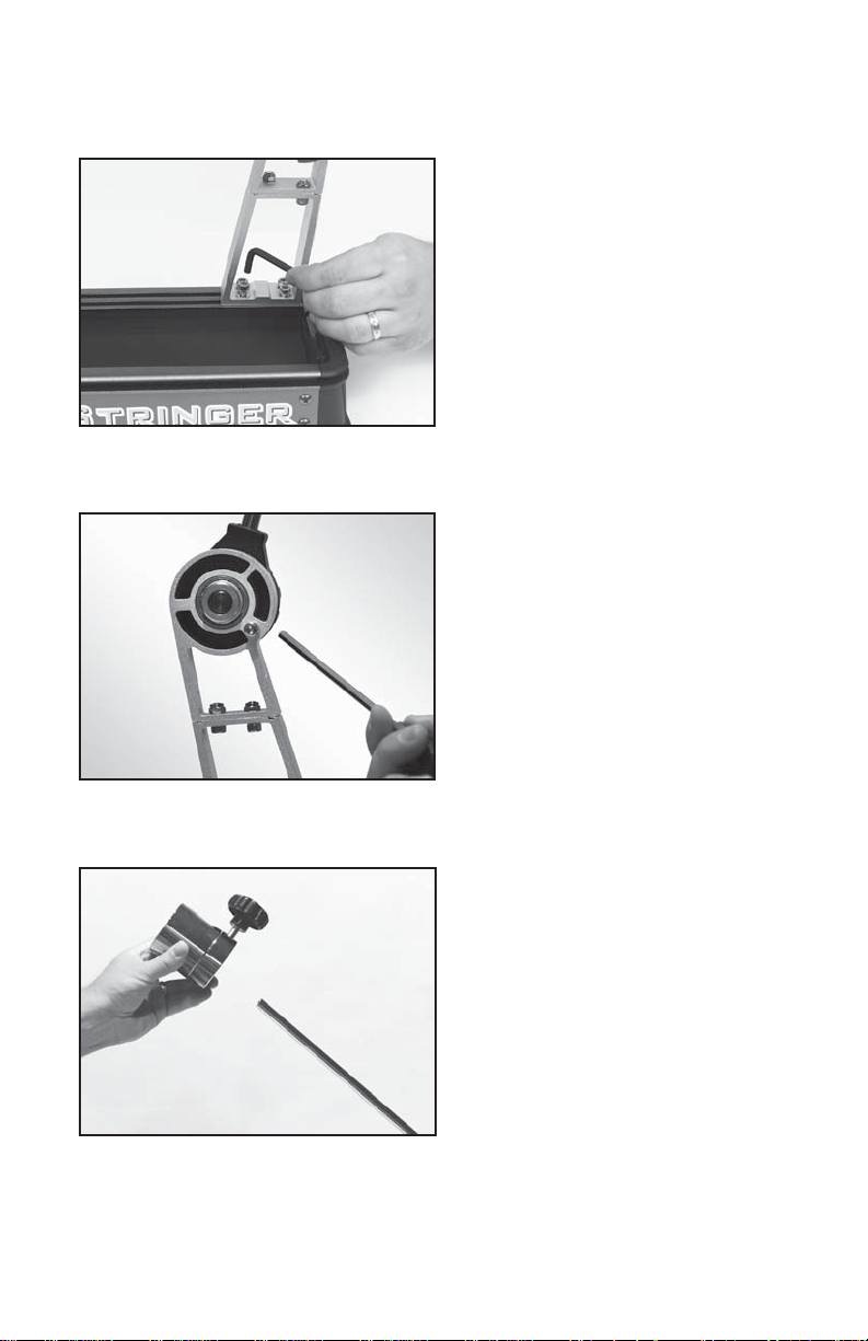
Winder Support Stand Installation
Remove the M5 bolts from the 2 brackets
located in the rear slots of the machine base
using the 5MM hex key. Slide the brackets
to the right end of the base and position the
winder stand over the brackets aligning the
holes in the base of the winder stand with the
holes in the brackets. Attach the winder support stand using the M5 bolts. Install all 4 bolts
loosely at fi rst and then tighten all securely.
Engaging the Drop Weight Bar Stop
The stringing machine is shipped with the
drop weight bar in the horizontal position. T o
limit the rotation of the drop weight bar and
prevent racquet damage during stringing,
the bar stop must be engaged.
Hold the drop weight bar in the vertical position as shown while turning the 5mm stop
screw located on the back side of the winder
stand clockwise.
Installing the Drop Weight
Remove the end cap from the tension bar and
slide the drop weight onto the bar. The weight
should be oriented with the knob end closest
to the string winder. Replace the end cap.
5
Page 6
ASSEMBLY INSTRUCTIONS
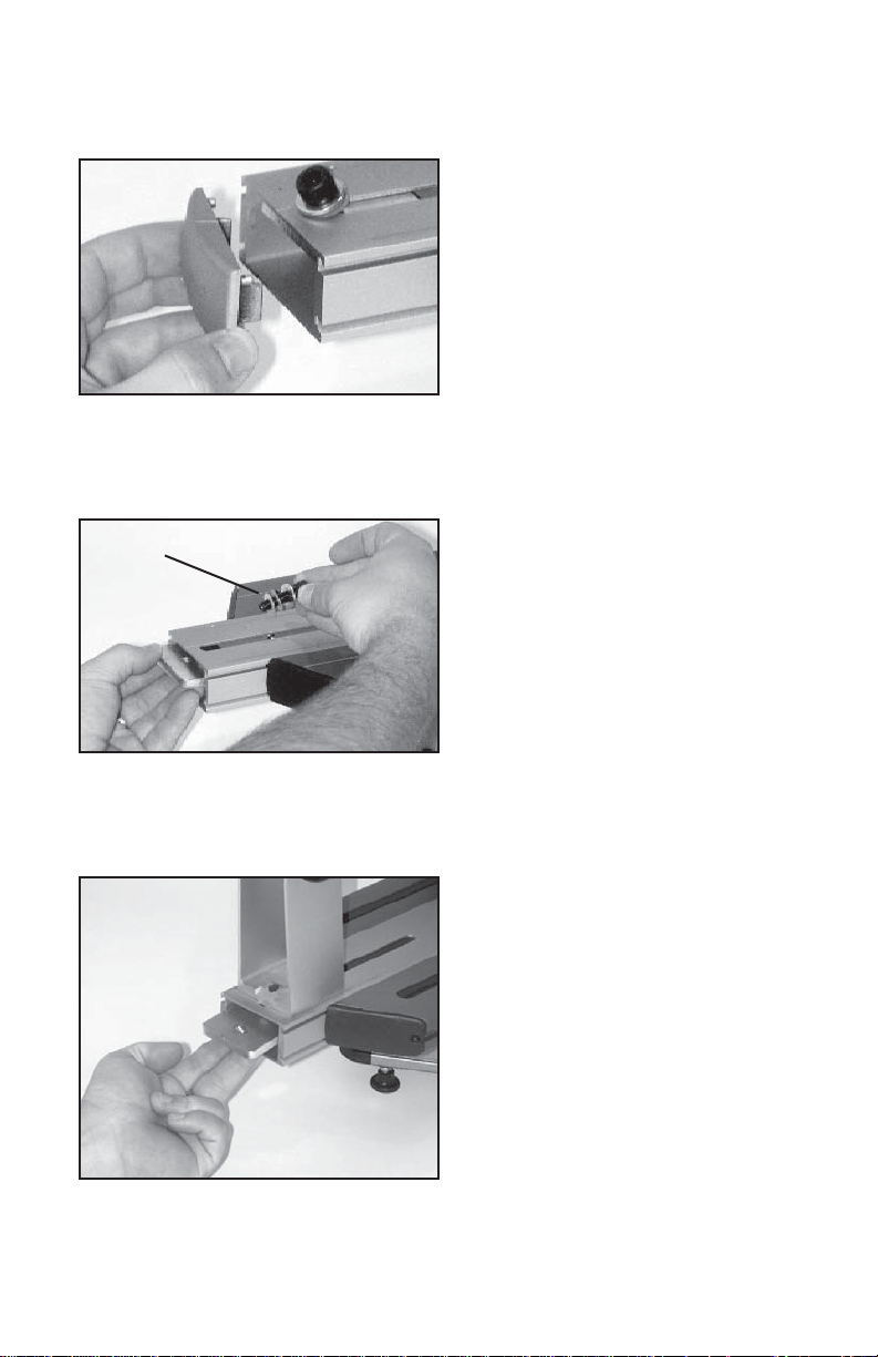
Support Post Installation
To install the support posts you must fi rst
remove the turntable end cap by grasping
the sides of the end cap and removing it, to
gain access to the inside of the turntable.
Repeat procedure on the opposite side of
the turntable.
If end caps are tight, a fl at blade screw driver
may be used to pry the end caps off.
Nylon
Washers
Remove Mounting Bolts
While holding the mounting plate on the
inside of the turntable remove the support
post mounting bolts.
Note: There are two Nylon washers that are
included for shipping purposes only. Remove
and discard the nylon washers.
Repeat procedure on the opposite side of
the turntable
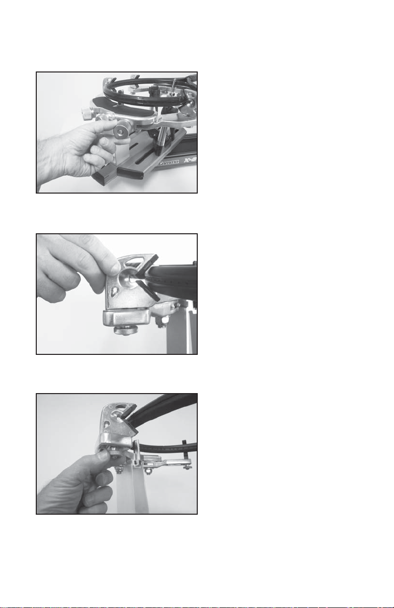
Installing the Frame Support Posts
Place the support post onto the central slot
of the turntable. While holding the mounting
plate against the inside top surface of the
turntable with your fi ngers, align the hole in
the support post with the hole in the mounting
plate. Install the mounting bolt through the
support post and into the plate by hand and
tighten with the 6 mm hex wrench. Re-install
the turntable end caps.
Repeat procedure on the opposite side of
the turntable
6
Page 7

ASSEMBLY INSTRUCTIONS
String Clamp Installation
The post of the string clamp and tube of
the string clamp base are treated with
grease to provide protection against corrosion during shipping. Remove any excessive grease with a clean cloth prior to use.
The post and tube may also be cleaned
with isopropyl alcohol. After this type of
thorough cleaning, the post and tube
should be treated with a light coating of
machine oil to protect the surfaces against
corrosion and to ensure smooth operation.
MOUNTING THE FRAME
Adjusting the Frame Support Posts
Loosen the lock bolts of the frame support
posts and space them apart with the frame
support slides separated by the approximate
length of the racquet head. Although it is not
required, it is good practice to center the support posts on the turntable. Lock one of the
posts in position by tightening the lock bolt and
position the other post until the frame support
slide is positioned near the inside surface of
the racquet frame. Securely tighten the lock
bolt of the second support post.
center posts should not contact the racquet prior to locking down the support posts.
Caution: To avoid racquet damage, the
Tightening the Frame Supports
Tighten the Frame Support Slides by turning the adjustment knob clockwise until
snug against the racquet frame and slight
resistance is felt.
Caution: Overtightening the Center Supports will stretch the head of the racquet and
could cause racquet damage.
7
Page 8
MOUNTING THE FRAME
Frame Shoulder Support Arm
Adjustment
Being sure the shoulder supports are free
to swivel in their mountings, simultaneously
rotate the shoulder support adjustment knobs
clockwise until both shoulder supports gently
and squarely contact the frame.
Frame Shoulder Support Adjustment
The shoulder supports are designed to rotate
and can be adjusted to provide maximum
support to the racquet frame. Rotate the
support so that the pads contact the frame
squarely when the arms are closed against
the racquet.
Securing the Frame
Lock the shoulder supports in position by
turning the knob at the base clockwise.
Repeat the adjustment procedure for the
remaining support post.
Re-tighten all of the frame supports in the
same order as before.
Do not overtighten any of the supports as
racquet damage may occur.
The supports should be tightened to the point
mounting system when the handle is grasped and attempts are made to move it. Should any
supports lose contact with the frame while stringing they should be re-tightened.
where the racquet frame will not move in the
8
Page 9

Badminton Shoulder Support Protection Pad Installation
Slide the badminton shoulder support cover
over the shoulder supports. There is no need
to remove the tennis shoulder supports.
Note: An optional badminton frame support
for the head of the racquet is available.
STRINGING THE FRAME
Setting Tension
To set the stringing tension, loosen the
locking knob on the side of the drop weight.
Slide the weight in the appropriate direction
until the face closest to the string gripper
is indexed with the desired tension mark on
the tension bar.
The drop weight is of a two piece design.
When assembled, it will accommodate tensions from 20 to 90 lbs For tensions from 8
to 20 lbs, remove the 5mm bolt on the face of
the drop weight, and use the smaller portion
of the weight as described above.
Note: Tensions above 77lbs require the
removal of the drop weight bar end cap.
9
Page 10

STRINGING THE FRAME
String Clamp Operation
The fi xed clamps are of a dual action de-
sign. The string clamp and the clamp base
operate independently of one another.
To clamp a string, lift the clamp head
and place the string between the jaws.
Depress the clamp head lever to secure
the string. The clamping pressure applied
to the string should be adjusted to provide
suffi cient pressure to secure the string
sion. The diamond coated gripper plates provide for increased friction between the clamps
and the string to allow for reduced clamping pressure while securing and holding the string
under tension.
Note: If the string slips in the string clamp while tensioning, adjust the gap between the
clamp jaws as per the instructions on page 15.
high tensions, additional tightness may be required.
when subjected to the desired pulling ten-
Base Clamp Operation
Rotate the lever lock clockwise to secure
the clamp base to the turntable.
Reverse the clamping procedure to unlock
the string clamp.
The lever should be tightened enough to
prevent clamp base slippage on the turntable, when the desired tension is placed
on the string. To go from the loose position
to the clamped position and back, generally requires about 1/2 to 3/4 quarters of a
turn. Although when stringing at extremely
Clamping the First Main String
To begin stringing the main strings, thread
the two ends of the string through the two
center holes at the appropriate end of the
frame and continue through the opposite
center holes. Thread one end of the string
through the adjacent grommet hole and
pull excess by hand.
Secure one of the strings using a string
clamp.
10
Page 11

STRINGING THE FRAME
Gripping the String
While holding the tension bar slightly above
horizontal, wrap the free string clockwise
around the gripper drum once and position
between the gripper jaw.
Gently turn the gripper clockwise while
squeezing the jaws together until all slack
in the string is removed.
Note: For proper operation, the string gripper jaw must be in the position shown. The
tension in the string provides the clamping
force to the jaws.
Pulling Tension
While securely holding the string gripper drum
with your hand, lift the tension bar above
horizontal and gently lower the bar under its
own weight. If the tension bar drops below
horizontal, repeat the above action until the
bar comes to rest parallel to the racquet.
WARNING: TO AVOID INJURY, KEEP FINGERS AWAY
FROM GRIPPER JAWS WHILE TENSIONING STRING.
When the correct tension is attained, the drop
weight bar will rest horizontally as shown. For
accurate tensioning, it must be lowered and
come to rest at horizontal without assistance.
Manually forcing the tension bar to the horizontal position will greatly increase the string
tension and may result in racquet damage.
If the tension bar comes to rest above horizontal, release the string by lifting the bar
and re-pull the string.
11
Page 12
STRINGING THE FRAME
Clamping the String
Secure the tensioned main string using
the remaining fi xed clamp. Release the
string from the gripper by raising the tension arm.
Repeat the procedure for all of the remaining main strings and tie off following the
racquet manufacturers recommendations.
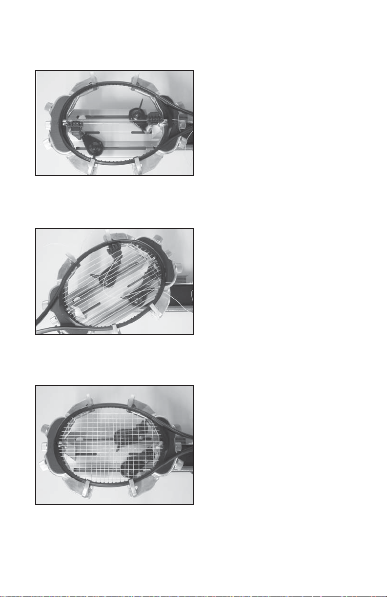
Weaving the Cross Strings
Follow the manufacturer's recommended
stringing pattern for one or two piece stringing.
This will determine the starting point for the
cross strings. If applicable, tie the fi rst cross
string using an appropriate starting knot.
Weave the cross strings over and under
the main strings being careful to alternate
the weave direction of each consecutive
cross string so as to be opposite of the
previously installed cross string.
Completing the String Job
Once the fi nal cross string is tensioned and
clamped, tie off at the appropriate hole specifi ed by the racquet manufacturer.
Remove the frame from the mounting system
by loosening the shoulder supports and
frame supports.
12
Page 13

ADDITIONAL FEATURES
Storage Drawers
There is one storage drawer located in the
base of the machine. The drawer opens from
the right side of the base and lock into the
end cap with a spring loaded latch.
To open the drawer depress the latch in the
face of the drawer and slide it to the right.
To close the drawer simply slide the drawer
back inside the base and the latch with automatically lock into place.
13
Page 14

P ATHFINDER A WL
The machine includes the pathfi nder string-
ing awl which creates a pathway between
or around strings to make inserting a string
through blocked grommets easier and
quicker.
Insert the awl through the grommet hole in
the same manner as for traditional awls. The
Pathfi nder awl must be in the closed position
before insertion.
Once the awl is inserted, pull the handle of
the awl outward while holding the tip section
in place. This leaves the outer sheath in the
grommet hole. Insert the end of the string
into the outer sheath.
While holding the string, slowly pull the sheath
out of the grommet hole to leave the free end
of the string exposed.
14
Page 15

MAINTENANCE & ADJUSTMENTS
Turntable Bushing Adjustment
The turntable bushing is adjusted at the factory for optimum performance. After time and
use, the turntable bushings may need minor
adjustment. An adjustment is indicated when
noticeable turntable looseness or wobble
occurs while stringing.
To adjust the fi t between the turntable pin
and the bushings, tighten the set screw at the
top of the bushing using a 3mm hex wrench.
Tighten until the turntable rotates smoothly
without excessive free play.
Adjusting the Clamps
The clamps provided with your stringing
machine will need minor adjustments according to string type, construction, and gauge.
T o adjust, route the string through the racquet
as if you were beginning the main strings.
Clamp the strings and pull tension. If the
string slips through the jaws of the clamp,
Adjustment
Knob
The clamp jaws must be clean and free from dirt, oil, and any string coating for them to grip
properly. Clean the clamp jaws with alcohol.
tighten the clamp by turning the adjustment
knob opposite of the handle, in the clockwise
direction. If the clamp leaves impressions or
damages the string, it is too tight and must
be adjusted by turning the adjustment knob
counterclockwise.
Note: The string clamps supplied with your stringing machine can accommodate tight string
patterns such as badminton. Depending on the string pattern, the clamp will spread the strings
slightly which will not compromise the quality of the string job.
Clamp Base Locking Nut Adjustment
In the event the Locking Lever rotation is
insuffi cient to ensure smooth operation of the
clamp base, very minor adjustments to the
Clamp Base Locking Nut can be made with
the supplied 17mm socket. Tighten or loosen
the locking nut in very small increments to
provide more clamping pressure or running
clearance as needed.
15
Page 16

TROUBLESHOOTING TIPS
PROBLEM SOLUTION
String slips in clamps - Adjust gap between clamp jaws
- Clean clamp jaws
String slips in gripper - Clean gripper jaws
- Make sure string is wrapped over top gripper
prior to inserting between gripper jaws
String clamp base slips on turntable - Clean bottom of clamp & top of turntable with
alcohol
- Adjust clamp base locking nut
With time and use, the clamping surfaces of your machine may become oily or dirty and result
CARE & CLEANING
in string or clamp slippage while stringing. Periodic cleaning of the String Clamps and String
Gripper is recommended. Knife sharpening stones work well for cleaning the diamond coated
string clamping surfaces. Cleaning with a solvent such as isopropyl alcohol and a mild abrasive
tool such as a toothbrush also works well to remove oily or greasy build up.
16
Page 17

NOTES
17
Page 18

PARTS LIST
PART # DESCRIPTION
4A TURNTABLE BUSHING
6A CAP SCREW
8A SET SCREW- M5x6
9 WASHER
14 WASHER
21A FRAME SUPPORT SLIDE
25 TENSION BAR
26 TENSION BAR CAP
27 DROP WEIGHT KNOB
28 FRONT WEIGHT- BADM
29 BACK WEIGHT- TENNIS
30 TENSION BAR DRUM
30A SET SCREW
31 STRING GRIPPER DRUM
34 RATCHET TEETH
35 RATCHET TEETH SPRING
83X TENSION BAR STOP SCREW
88 CAP SCREW
133 FRAME SUPP SLIDE SCREW
140 MTNG STAND TOP PLATE
141 MTNG STAND TOP PAD
144 SHLDER SUPP LOCK KNOB
146A SUPP ARM ADJUST KNOB
161 WINDER BEARING
162 GRIPPER PIVOT PIN
163 PIVOT PIN RETAINER COLLAR
255 BASE
256 TRAY PAD
257 LOWER WINDER STAND
258 UPPER WINDER STAND
259 SLIDE BRACKET
261 TURNTABLE END CAP
262 SUPP POST MT PLATE
265 DRAWER END CAP
266 BASE CORNER CAP
267 TT RIGHT END CAP
268 TT LEFT END CAP
PART # DESCRIPTION
271 SUPPORT POST
278 BASE CORNER CAP
284 TURNTABLE
288 BASE END CAP
301 RUBBER FOOT
319 TT RISER RING
323 SMALL DRAWER
356 QM ARM (LONG) RIGHT
357 QM ARM (LONG) LEFT
381 SHOULDER V-MOUNT
MCFCT COMP FIXED CLAMP
MRSG ROTATIONAL GRIPPER
MQAC11 TALL QA BASE CLAMP
TOOLS & ACCESSORIES
69 3MM HEX WRENCH*
71 6MM T-HANDLE HEX WRENCH*
98 10MM WRENCH*
108 UTILITY KNIFE*
109 NEEDLE NOSE PLIERS*
229 5MM HEX WRENCH*
MA STRINGER’S AWL*
MBMSP11 BADM SHOULDER SUPP COVER
MFSPP11 FRAME SUPPORT PADS
SHORT BADMINTON (SB)
SQUASH (SQ)
TENNIS (T)
TAPERED BADMINTON (B)
MMSPP13 V-MOUNT SUPP PADS
MPSA PATHFINDER AWL*
* (NOT SHOWN)
OPTIONAL TOOLS & ACCESS
MBFC BADM FLOATING CLAMP
MBFS11 BADM FRAME SUPPORT
MBMSS11 BADM MOUNTING SYS UPG
MDCSC BADM FIXED CLAMP
MPMC MACHINE COVER
MPG STARTING CLAMP
MPS CLEANING STONE
MPXFS FLOOR STAND
SGSM STRINGER’S MA T
18
Page 19

MQAC11
PARTS DRAWING
MCFCT
MMSPP
146A
26
28
133
268
261
140
14
262
141
357
96A
267
288
271
284
4A
21A
381
144
356
83X
319
258
257
259
25
163
161
259
88
30
31
162
29
30A
35
34
MFSPP11
27
MRSG
323
266
265
278
8A
255
19
256
301
SQ SB T B
MBMSP11
Page 20

MMAN-36
(MGX6F-12)
GAMMA SPORTS
200 Waterfront Drive
Pittsburgh, Pennsylvania 15222
Phone: 800.333.0337 Fax: 412.323.0317
Visit our website at www.gammasports.com
Copyright 2012 GAMMA Sports - All Rights Reserved
 Loading...