

Gamma X-6 Owner's Manual

OWNER'S MANUAL
Issue 4 - November 2012
X-6
STRINGING MACHINE

2
LIMITED WARRANTY
GAMMA Sports (GAMMA) warrants to the original purchaser that the X-STRINGER stringing machine ("EQUIPMENT")
purchased is free from defects in materials and workmanship for a period of fi ve (5) years from the date of original purchase
for mechanical parts (excluding any electrical parts and string clamps), and for a period of one (1) year from the date of
purchase for any electrical parts and string clamps. Should any defects develop under normal use within the specifi ed time
periods, GAMMA will at its option, repair or replace the defective EQUIPMENT provided it is returned to GAMMA prepaid
at the purchaser's expense. This warranty does not apply to any damage or defect caused by negligence, abuse, misuse,
unauthorized alteration, shipping, handling, or part wear and tear as a result of normal use.
Routine maintenance, adjustment, and cleaning required to ensure proper operation are the responsibility of the purchaser
and are not covered under the terms of this warranty. These include, but are not limited to: String Clamp adjustment, as
described on page 13, Turntable Bushing Adjustment, as described on page 13 and the Rotational String Gripper.
GAMMA's obligation under this warranty is limited to repair or replacement of defective EQUIPMENT , and no one is authorized
to promise any other liability. GAMMA shall in no event be liable for any incidental or consequential damages.
T o return defective EQUIPMENT , a return authorization (RA#) must be obtained from a GAMMA customer service representative. The RA# must be marked on the outside of the shipping carton being returned. All returns must be shipped prepaid by
the customer to GAMMA. Please retain the original shipping carton and packing materials for any future shipments. GAMMA
will not be responsible for machines which are not sent in the original undamaged packaging.
A GAMMA Care Service Plan is also available through GAMMA customer service, call 800.333.0337 for details.
X-6
MGX6-12 OWNER’S MANUAL
TABLE OF CONTENTS
WARRANTY ................................................................................................P AGE 2
FEATURES .................................................................................................PAGE 3
ASSEMBLY INSTRUCTIONS .....................................................................PAGE 4
MOUNTING THE FRAME ...........................................................................PAGE 6
STRINGING THE FRAME ..........................................................................PAGE 8
ADDITIONAL FEATURES ......................................................................... PAGE 11
PATHFINDER AWL ...................................................................................PAGE 12
MAINTENANCE & ADJUSTMENTS .........................................................PAGE 13
TROUBLESHOOTING TIPS .....................................................................P AGE 13
PARTS LIST ..............................................................................................PAGE 14
PARTS DRAWING ....................................................................................PAGE 15
3
MACHINE FEATURES
Drop Weight Tensioner with 8 to 90 lbs Tension Range and
Permanently Engraved Weight Scale
Professional Six Point “Quick Mount” Racquet Mounting
System- Accommodates All Racquets
Parallel Jaw Rotating Ratchet Gripper with Diamond Dust
Coated Gripping Surfaces
Two Composite Floating Clamps with Thumb Screw
Adjustment
High Strength Extruded Aluminum Base with Durable
Anodized Finish and Convenient Padded Tool Tray
Unique Internal Drawer System for Storing Tools and Adaptors
FEATURES
4
ASSEMBLY INSTRUCTIONS
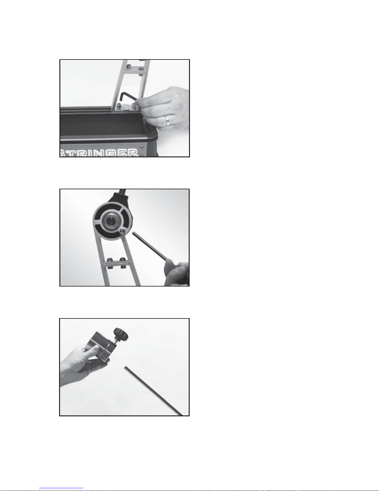
Engaging the Drop Weight Bar Stop
The stringing machine is shipped with the
drop weight bar in the horizontal position. T o
limit the rotation of the drop weight bar and
prevent racquet damage during stringing,
the bar stop must be engaged.
Hold the drop weight bar in the vertical position as shown while turning the 5mm stop
screw located on the back side of the winder
stand clockwise.
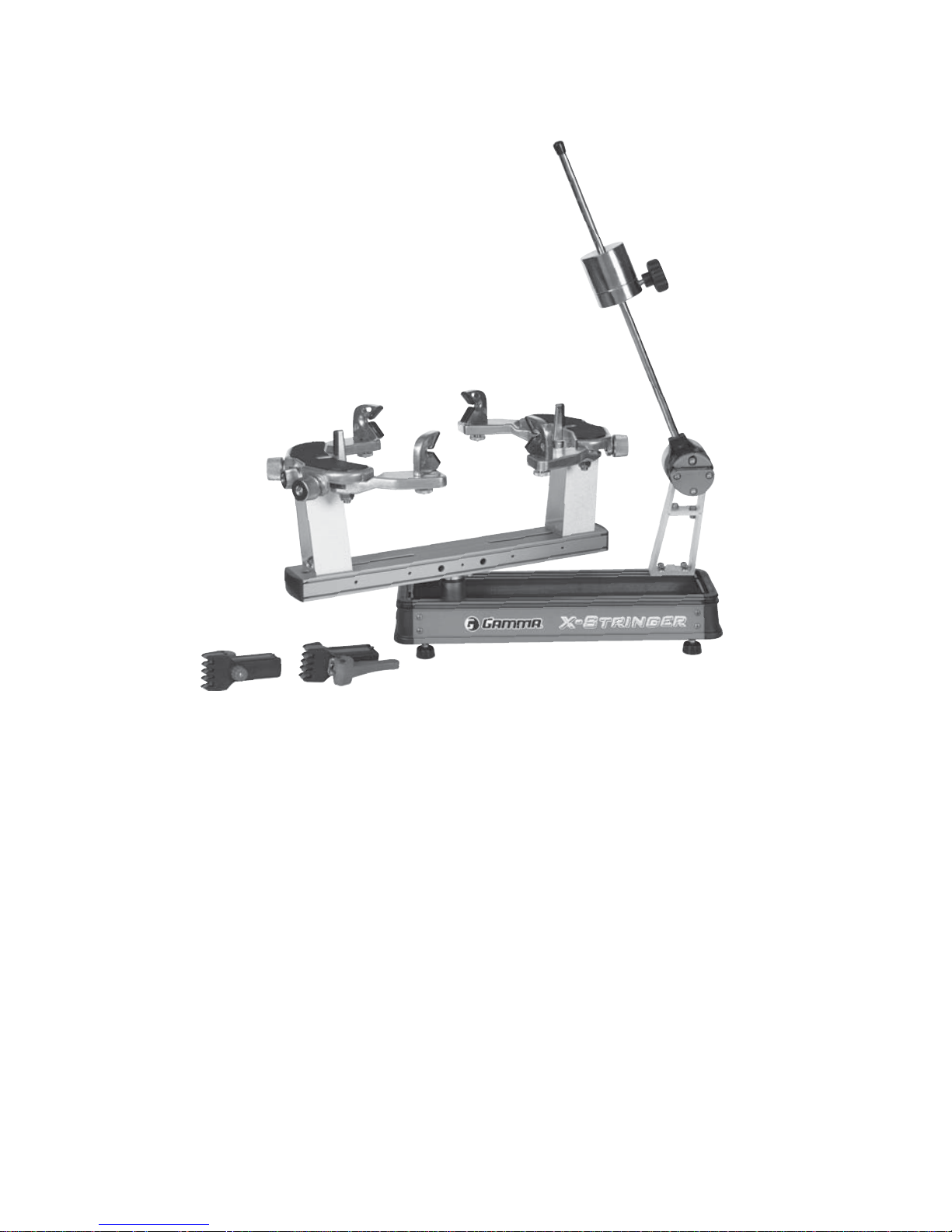
Winder Support Stand Installation
Remove the M5 bolts from the 2 brackets
located in the rear slots of the machine base
using the 5MM hex key. Slide the brackets
to the right end of the base and position the
winder stand over the brackets aligning the
holes in the base of the winder stand with the
holes in the brackets. Attach the winder support stand using the M5 bolts. Install all 4 bolts
loosely at fi rst and then tighten all securely.
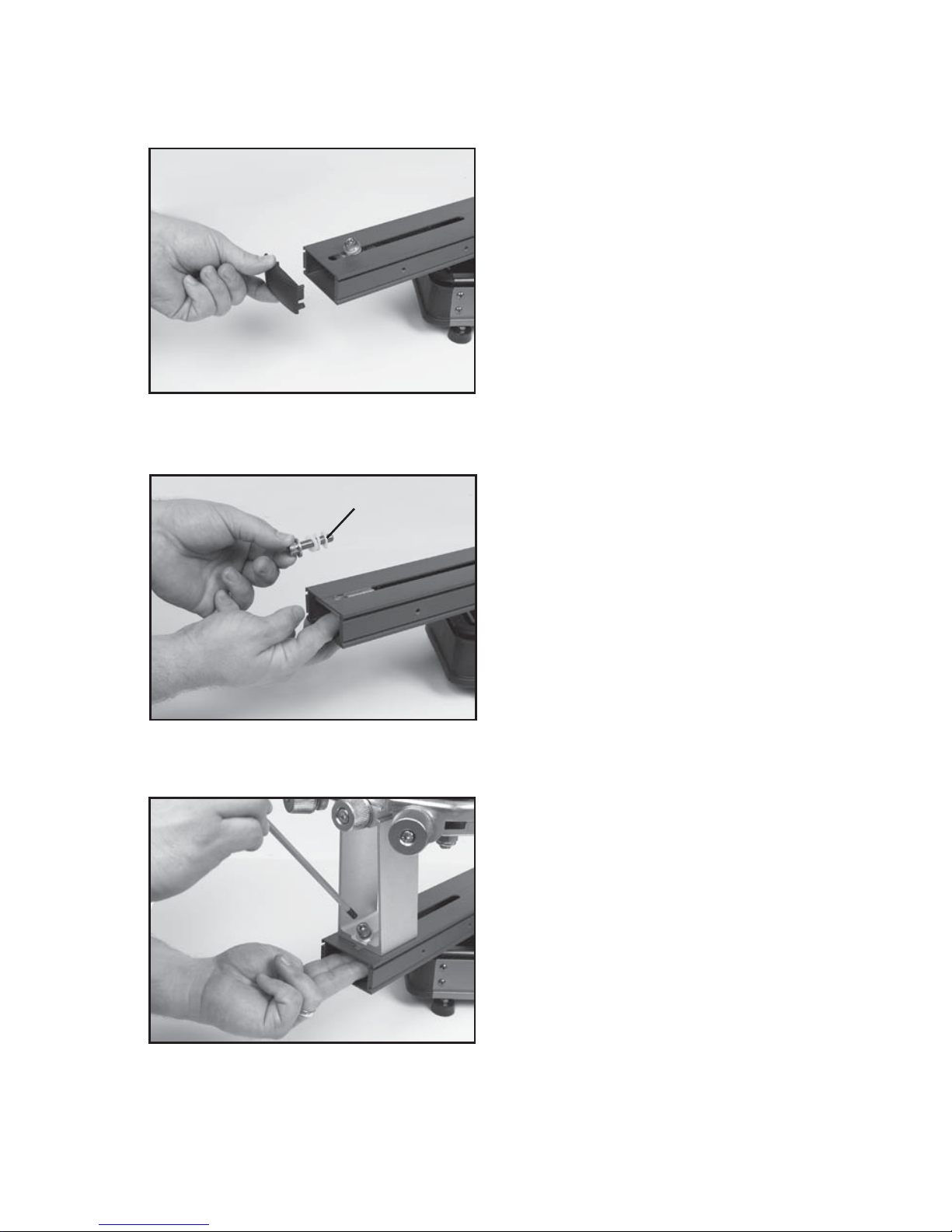
Installing the Drop Weight
Remove the end cap from the tension bar and
slide the drop weight onto the bar. The weight
should be oriented with the knob end closest
to the string winder. Replace the end cap.
5
ASSEMBLY INSTRUCTIONS
Installing the Frame Support Posts
Place the support post onto the central slot
of the turntable. While holding the mounting
plate against the inside top surface of the
turntable with your fi ngers, align the hole in
the support post with the hole in the mounting
plate. Install the mounting bolt through the
support post and into the plate by hand and
tighten with the 6 mm hex wrench. Re-install
the turntable end caps.
Repeat procedure on the opposite side of
the turntable
Remove Mounting Bolts
While holding the mounting plate on the
inside of the turntable remove the support
post mounting bolts.
Note: There are two Nylon washers that are
included for shipping purposes only. Remove
and discard the nylon washers.
Repeat procedure on the opposite side of
the turntable
Support Post Installation
To install the support posts you must fi rst
remove the turntable end cap by grasping
the sides of the end cap and removing it, to
gain access to the inside of the turntable.
Repeat procedure on the opposite side of
the turntable.
If end caps are tight, a fl at blade screw driver
may be used to pry the end caps off.
Nylon
Washers
 Loading...