

Page 1
PROGRESSION
ST
OO
WNER'S MANUWNER'S MANU
O
WNER'S MANU
OO
WNER'S MANUWNER'S MANU
Issue 2 / Version E - Oct. 28, 1997Issue 2 / Version E - Oct. 28, 1997
Issue 2 / Version E - Oct. 28, 1997
Issue 2 / Version E - Oct. 28, 1997Issue 2 / Version E - Oct. 28, 1997
Copyright 1997 GAMMA Sports - All Rights Reserved
ALAL
AL
ALAL
Page 2

PROGRESSION S T
OWNER'S MANUAL
TABLE OF CONTENTS
PAGE 1................................................................................................WARRANTY
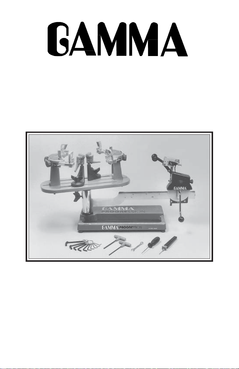
PAGE 2 ................................................................................................. FEATURES
PAGE 3..................................................................... ASSEMBLY INSTRUCTIONS
PAGE 6........................................................................... MOUNTING THE FRAME
PAGE 7...........................................................................STRINGING THE FRAME
PAGE 10 ........................................................................................ MAINTENANCE
PAGE 13 .................................................................................. PATHFINDER AWL
PAGE 14 ..................................................................... TROUBLESHOOTING TIPS
PAGE 15 .............................................................................................. PARTS LIST
PAGE 16 ........................................................................ COMPONENT DRAWING
PAGE 17 .....................................................................MOUNTING STAND PARTS
LIMITED WARRANTY
GAMMA SPORTS ("GAMMA") warrants to the original purchaser that the GAMMA PROGRESSION ST stringing machine
("EQUIPMENT") purchased is free from defects in materials and workmanship for a period of five (5) years from the date of
original purchase for mechanical parts (excluding string clamps), and for a period of one (1) year from the date of purchase
for string clamps. Should any defects develop under normal use within the specified time periods, GAMMA will at its option,
repair or replace the defective EQUIPMENT provided it is returned to GAMMA prepaid at the purchaser's expense. This
warranty does not apply to any damage or defect caused by negligence, abuse, misuse, unauthorized alteration, shipping,
handling, or part wear and tear as a result of normal use.
GAMMA's obligation under this warranty is limited to repair or replacement of defective EQUIPMENT, and no one is authorized
to promise any other liability. GAMMA shall in no event be liable for any incidental or consequential damages.
To return defective EQUIPMENT, a return authorization (RA#) must be obtained from a GAMMA customer service
representative by calling 1-800-333-0337. The RA# must be marked on the outside of the shipping carton being returned. All
returns must be shipped prepaid by the customer to GAMMA. Please retain the original shipping carton and packing materials
for any future shipments. GAMMA will not be responsible for machines which are not sent in the original undamaged
packaging.
1
Page 3
FEA TURES
Professional Six Point Mounting System - Accomodates All
Racquets Without Adapters
Parallel Jaw String Gripper w/ Diamond Dust Coated Gripping
Surfaces
Professional Dual Action, Diamond Dust Coated, Fixed String
Clamps
Durable Polystyrene Base Cover w/ Convenient Padded Tool
Tray
Strong, Light Weight, Powder Coated Molded Aluminum
Construction
2
Page 4
ASSEMBLY INSTRUCTIONS
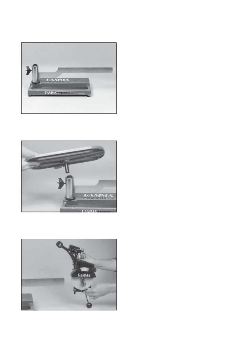
Machine Base Setup
Remove all parts from the shipping cartons.
Set the base with attached tensioner bar onto
a table or floor.
When purchased with the optional floor stand,
it is more convenient to attach the base to the
floor stand at this point. See instructions
provided with the optional floor stand.
Installing the Turntable
The turntable is located on top of the foam
packing in the the shipping carton.
Insert the center post of the turntable into the
bushing located in the top of the tensioner bar
post.
Installing the Tensioner
Remove the button head screw and washer
located at the end of the tensioner bar with
the 3 mm hex wrench provided. Slide the
tensioner onto the bar, being careful to align
the bar with all of the bearings and the drive
gear with the gear track. Replace the set
screw and washer into the end of the tensioner
bar.
Note: The tensioner bar is equipped with a
tensioner travel stop to limit travel of the
tensioner along the bar. See page 7 for more
details about this feature.
3
Page 5
ASSEMBLY INSTRUCTIONS
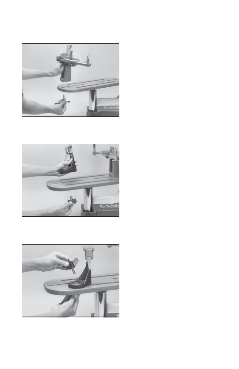
Installing the Frame Support Posts
The Progression ST support post assemblies are precision aligned at the factory and
are marked for proper installation on the
turntable.
Install the support post with the dot on its
base to an identical dot on the turntable. Align
the threaded hole in the bottom of the frame
support post with the slot in the turntable.
Screw the lever lock bolt with washer into the
bottom of the support post and tighten
gently.Position the washer with the rounded
edge toward the turntable. Repeat procedure
on the opposite side of the turntable.
Fixed Clamp Installation
To install the clamps, remove the winged
lock knob to separate the knob from the lower
guide bushing. Be careful not to lose the
thrust bearing components located in the
center recess of the knob.
Align the clamp base with the clamp slot of
the turntable base. Insert the lower guide
bushing into the clamp from the bottom of the
turntable making sure to engage the guide
with the clamp slot.
Place the load bushing into the top of the
clamp base mating it to the lower guide
bushing. After checking that the thrust bearing is positioned correctly in the base of the
winged lock knob, screw the knob into the
base bushing until fully seated.
The post of the string clamp head and tube of
the string clamp base are treated with grease
to provide protection against corrosion during shipping. Remove any excessive grease
with a clean cloth prior to use. The post and
tube may also be cleaned with isopropyl
the post and tube should be treated with a light coating of machine oil to protect the surfaces
against corrosion and to ensure smooth operation.
alcohol. After this type of thorough cleaning,
4
Page 6

ASSEMBLY INSTRUCTIONS
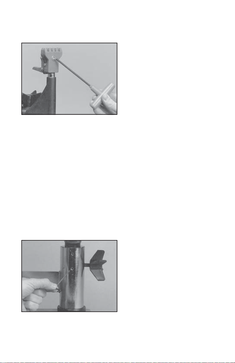
Locking the Turntable
The turntable may be locked in any position.
The turntable winged lock knob is packed
separately in the accessory polybag. Install
the lock knob into the threaded hole located
on the side of the tensioner bar post.
Rotate the knob clockwise to lock the turntable, and counter-clockwise to release the
turntable.
5
Page 7

MOUNTING THE FRAME
Adjusting the Frame Support Posts
Place the racquet frame over the center
posts and onto the frame support. Loosen the
lever lock bolt on one support post. Slide the
post outward until the center support of the
racquet support slide is positioned near the
inside surface of the racquet frame. Securely
tighten the lever lock bolt.
Adjust the opposite post using the same
procedure.
Caution: To avoid racquet damage, the center posts should not contact the racquet prior
to fixing the support posts.
Adjusting the Frame Shoulder Supports
Being sure the shoulder supports are free to
swivel in thier mountings, simultaneously
rotate the shoulder support adjustment knobs
clockwise until both shoulder supports gently
and squarely contact the frame.
Tighten the Frame Support Slides at the
head and throat of the racquet until they
gently contact the frame between the two
center main string grommets.
Securing the Frame
Lock the shoulder supports in position by
turning the knob at the base clockwise.
Repeat the adjustment procedure for the
remaining support post.
Re-tighten all of the frame supports in the
same order as before.
Do not overtighten any of the supports as
racquet damage may occur.
The supports should be tightened to the point
mounting system when the handle is grasped and attempts are made to move it. Should any
supports lose contact with the frame while stringing, they should be re-tightened.
where the racquet frame will not move in the
6
Page 8

STRINGING THE FRAME
Setting Tension
The Progression ST utilizes a rotary adjusting knob along with a linear tension scale to
indicate the tension setting. The scale is
divided into 3 lb increments and each 1/3 turn
of the tension knob changes tension by 1 lb.
To set the desired tension, rotate the tension
knob and align the mark on the spring guide
with the desired tension setting on the scale.
When the “0” mark on the knob aligns with the
line on the knob support the tension will be
that indicated on the scale. To increase ten-
wise until the “1” or “2” mark on the knob aligns with the line on the knob support. To decrease
tension by 1 or 2 lbs, turn the knob clockwise until the “2” or “1” mark on the knob aligns with
the line on the knob support.
Travel Stop
sion by 1 or 2 lbs turn the knob counterclock-
Tensioner Travel Stop
To prevent contact between the tension head
and the racquet and/or turntable, a stop
screw is located about midpoint along the
tensioner bar below the gear track. In the
event the tension head must be moved closer
to the racquet, turn the stop screw counterclockwise with the 5 mm hex wrench until the
end of the stop screw no longer protrudes
beyond the surface of the tensioner bar. To
re-engage the stop, simply turn the stop
screw clockwise until the screw is seated
against the tensioner bar.
Fixed Clamp Operation - Step 1
The fixed clamps for the Progression ST are
of a dual action design. The string clamp and
the clamp base operate independently of one
another.
To clamp a string, lift the clamp head and
place the string between the jaws. Depress
the clamp head lever to secure the string.
The clamping pressure applied to the string
should be adjusted to provide sufficient pressure to secure the string when subjected to
the desired pulling tension. The diamond
friction between the clamps and the string to allow for reduced clamping pressure while securing
and holding the string under tension.
coated gripper plates provide for increased
7
Page 9

STRINGING THE FRAME
Fixed Clamp Operation - Step 2
Rotate the winged lock knob clockwise to
secure the clamp base to the turntable.
Reverse the clamping procedure to unlock
the string clamp.
The winged lock knob should be tightened
enough to prevent clamp base slippage on
the turntable, when the desired tension is
placed on the string. To go from the loose
position to the clamped position and back,
generally requires about 1/2 to 3/4 quarters
tremely high tensions, additional tightness may be required. Note: If the string slips in the
string clamp while tensioning, adjust the gap between the clamp jaws as per the
instructions on page 11.
of a turn. Although when stringing at ex-
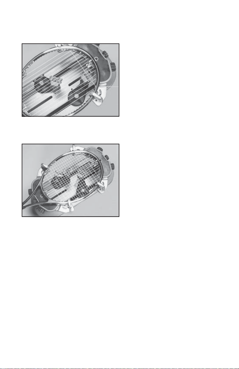
Clamping the First Main String
To begin stringing the main strings, thread
the two ends of the string through the two
center holes at the appropriate end of the
frame and continue through the opposite
center holes. Thread one end of the string
through the adjacent grommet hole and pull
excess by hand.
Secure one of the strings using a string
clamp.
Pulling Tension
Wrap the loose section of string once around
the roller guide and insert the string between
the diamoind dust coated string gripper
plates. Pull the string perpendicular to the
gripper plates while slowly rotating the
tensioner crank clockwise until the brake
lever pops out of the latching block. The
string is now tensioned and can be clamped
in place with the remaining fixed clamp.
Repeat the above steps until all main strings
are installed. Tie off ends of main strings as
per racquet manufacturers recommendations.
8
Page 10
STRINGING THE FRAME
Weaving the Cross Strings
Weave the cross strings over and under the
main strings being careful to alternate the
weave direction of each consecutive cross
string so as to be opposite of the previously
installed cross string.
Once the final cross string is tensioned and
clamped, tie off at the appropriate hole specified by the racquet manufacturer.
9
Page 11

MAINTENANCE
Tension Calibration Procedure - Step 1
Set the tension to 60 lbs. as indicated by the
linear scale and rotary knob. Place the string
on one end of a tension calibrator into a string
clamp and secure. Place string located on
the other end of the calibrator into the string
tensioner and apply tension. If the brake
lever releases before 60 lbs. or after 60 lbs.,
the tension head should be calibrated as
follows.
Tension Calibration Procedure - Step 2
Loosen the plastic locking screw located on
the side of the latching block as shown. The
plastic screw is used to hold the adjustment
screw in place.
Tension Calibration Procedure - Step 3
If the lever releases before 60 lbs., turn the
adjustment screw located on the left side of
the latch block counter-clockwise to increase
the engagement of the brake release latch
with the brake lever. Repeat step 1 and
adjust until the correct tension is indicated on
the calibrator.
If the tension indicated in step 1 is greater
than 60 lbs., turn the adjustment screw clockwise to reduce the engagement of the brake
release latch with the brake lever. Repeat
step 1 and adjust until the correct tension is
indicated on the calibrator.
10
Page 12
MAINTENANCE
Adjusting the String Clamps
The clamps provided with your stringing machine will need minor adjustments according
to what string type, construction, and gauge
you are using.
To adjust, route the string through the racquet
as if you were beginning the main strings.
Clamp the strings and pull tension. If the
string slips through the jaws of the clamp,
tighten the clamp by turning the flat head
screw clockwise with the 4 mm hex wrench
located on the side of the string clamp oppo-
sions or damages the string, it is too tight and must be adjusted by turning the hex screw
counterclockwise.
The clamp jaws must be clean and free from dirt, oil, and any string coating for them to grip
properly. The diamond dust coated clamping surfaces should be cleaned periodically by
removing the flat head screw to completely expose the clamping surfaces. Clean the clamping
surfaces with alcohol and a nylon brush until all surfaces are clean. Replace the screw and
spring to re-assemble the clamps.
Note: The string clamps supplied with your Gamma stringing machine can accomodate tight
string patterns such as badminton. Depending on the string pattern, the clamp may spread the
strings slightly which will not compromise the quality of the string job.
site of the handle. If the clamp leaves impres-
Turntable Bushing Adjustment
The Progression ST is adjusted at the factory
for optimum performance. After time and
use, the turntable bushings may need minor
adjustment. An adjustment is indicated when
noticeable turntable looseness or wobble
occurs while stringing.
To adjust the fit between the turntable pin and
the bushings, tighten the set screws located
on the back side of the tensioner bar post
using a 3mm hex wrench. Tighten until the
turntable rotates smoothly without excessive
free play.
11
Page 13
MAINTENANCE
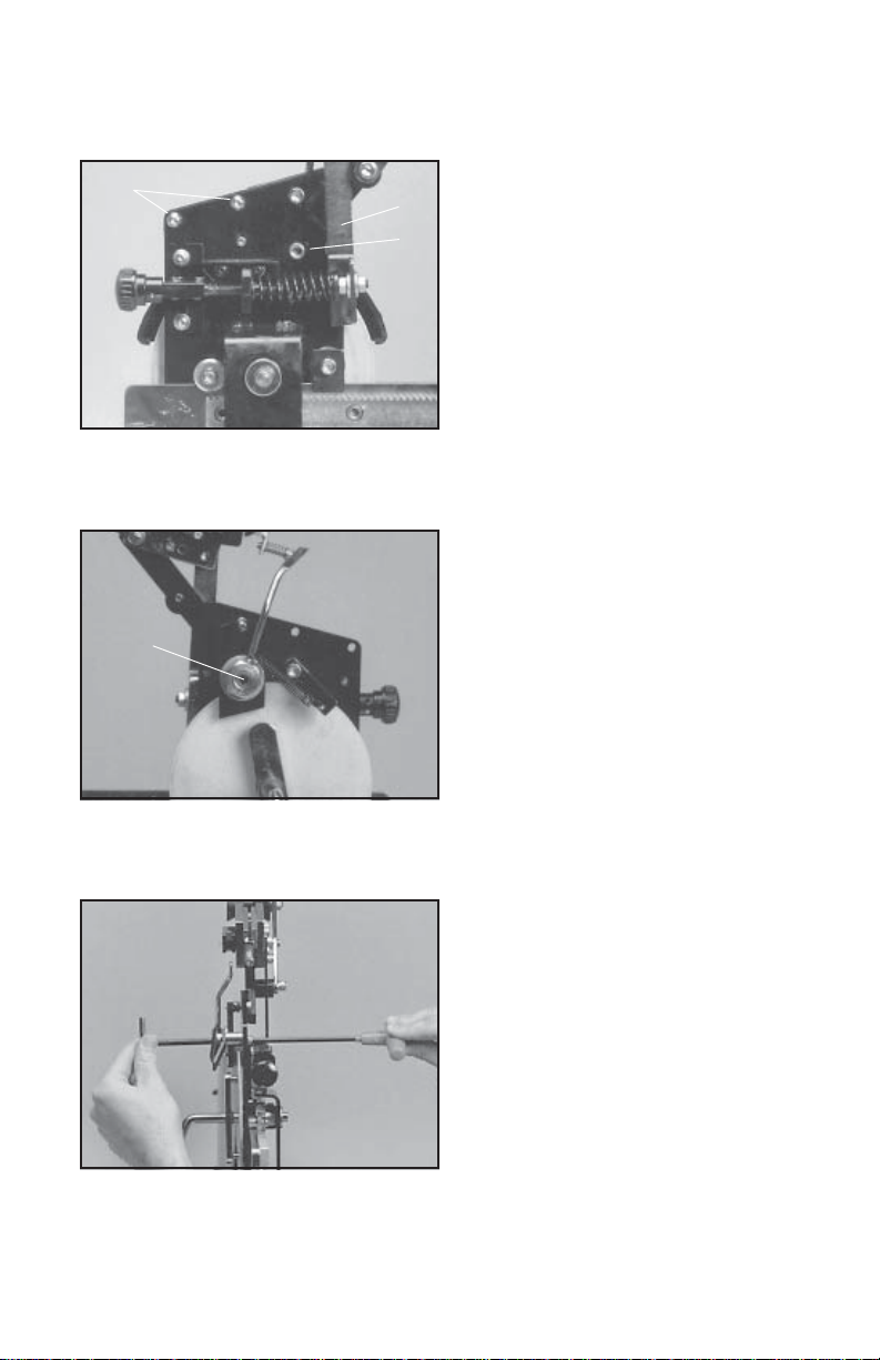
A
A
B
A - Cover Screws B - Lock Bolt
C
Adjusting the Tensioner Brake - Step 1
After stringing many racquets, the brake of
the tensioner may need to be adjusted. To
tighten the braking mechanism, the cover of
the tensioner must be removed. To remove
the cover, remove the 2 button head screws
located on the back side of the tensioner
frame near the top of the frame, and the flat
head screw located behind the tensioner
lever on the back side of the tensioner frame
using the 3 mm hex wrench. With the brake
lever released remove the cover.
Adjusting the Tensioner Brake - Step 2
With the cover removed, and the brake lever
engaged, loosen the lower hex bolt located
on the back side of the tensioner frame with
the 10 mm box wrench. Note: The hex bolt
should only be loosened until loose enough
to turned by hand and must not be removed
completely.
C - Brake Adjustment Bolt
Adjusting the Tensioner Brake - Step 3
With the hex bolt loosened and the brake
lever engaged in the latch, insert the 6 mm
hex wrench into the set screw locted inside
the nut located at the base of the brake lever.
To tighten the braking mechanism, turn the
set screw counter clockwise by about 1/8
tunr. Retighten the hex bolt on the back side
of the tensioner frame and check for brake
tightness. The tensioner should move freely
along the track with the brake lever engaged
and should hold tension with the brake lever
peat steps above until properly adjusted. After adjustment is complete, replace the tensioner
cover by aligning the holes of the cover with the holes in the tensioner frame and secure with
the 2 button head screws and flat head screw.
released. If more adjustment is needed, re-
12
Page 14

PATHFINDER AWL
The Progression ST includes the new Pathfinder stringing awl which creates a pathway
between or around strings to make inserting
a string through tight gromets easier and
quicker.
Insert the awl through the grommet hole in
the same manner as for traditional awls. The
Pathfinder awl must be in the closed position
before insertion.
Once the awl is inserted, pull the handle of
the awl outward while holding the tip section
in place, leaving the outer sheath in the
grommet hole.
Insert the end of the string into the center of
the sheath.
While holding pressure on the string, slowly
pull the sheath out of the grommet hole to
leave the end of the string exposed.
13
Page 15

TROUBLESHOOTING TIPS
PROBLEM SOLUTION
String slips in clamps
- Adjust gap between jaws
- Clean clamp jaws
String slips in gripper
String clamp slips on base - Clean base of clamp and top of
String clamp winged lock knob is difficult to
turn
String tension too tight or too loose
For additional assistance, contact Gamma Sports Customer Service at 1-800-333-0337
- Clean gripper jaws
- Adjust Gripper Jaw Stop Screw
turntable
- Check for proper position of thrust
bearing in the base of the winged lock
knob
- Check tension using a tension calibrator
and adjust machine calibration if necessary
CARE and CLEANING
With time and use, the clamping surfaces of your machine may become oily or dirty and result
in string or clamp slippage while stringing. Periodic cleaning of the following parts is recommended.
String Clamps
Clean the inside gripping surfaces of the string clamp jaws by inserting a cloth or pipe cleaner
soaked with isopropyl alcohol between the jaws and rub back and forth. If the build-up is
excessive, dismantle the string clamp jaws to expose the gripping surfaces by removing the
adjustment screw. Using a small nylon brush, (such as a toothbrush), scrub the inside surfaces
until all debris is removed. Clean the jaws with isopropyl alcohol and re-assemble.
String Clamp Base
Clean the base of the clamps and the top of the turntable with isopropyl alcohol.
String Gripper
Clean inner gripping surfaces with isopropyl acohol soaked cloth or pipe cleaner.
14
Page 16

ST
Parts Listing
PART #
1
2
3
4
5
6
7
8
9
11
12
13
14
15
17
21
22
23
24
104
105
106
107
DESCRIPTION
ALUMINUM BASE
BASE COVER
TRAY PAD
TURNTABLE BUSHING
RUBBER FEET
CAP SCREW
FOOT NUT
BUSHING SET SCREW
WASHER
TURNTABLE
TURNTABLE PIN
POST LOCK LEVER
WASHER
SUPPORT POST
CAP SCREW
FRAME SUPPORT SLIDE
BADMINTON ADAPTER
TENNIS ADAPTER
KNOB
TENSIONER ASSEMBLY
RETAINER SCREW
TABLE BRAKE KNOB
TENSIONER BAR
PART #
50
52
53
54
55
56
57
57A
58
59
60
61
62
66
67
67A
68
99
69
70
71
72
73
74
DESCRIPTION
PIVOT PIN
CLAMP HEAD ASSEMBLY
CLAMP BASE ASSEMBLY
CLAMP BASE
GUIDE BUSHING
GUIDE BUSHING NUT
LOAD BUSHING
RADIAL BEARING
WINGED KNOB
FIXED JAW
LOOSE JAW
PIVOT BLOCK
LEVER
RETURN SPRING
HEX SCREW - FLAT HEAD
PIVOT BLOCK NUT
O-RING
HEX WRENCH / 2.5MM
HEX WRENCH / 3MM
HEX WRENCH / 4MM
HEX WRENCH / 5MM
HEX WRENCH / 6MM
PATHFINDER AWL
STRINGERS AWL
15
Page 17
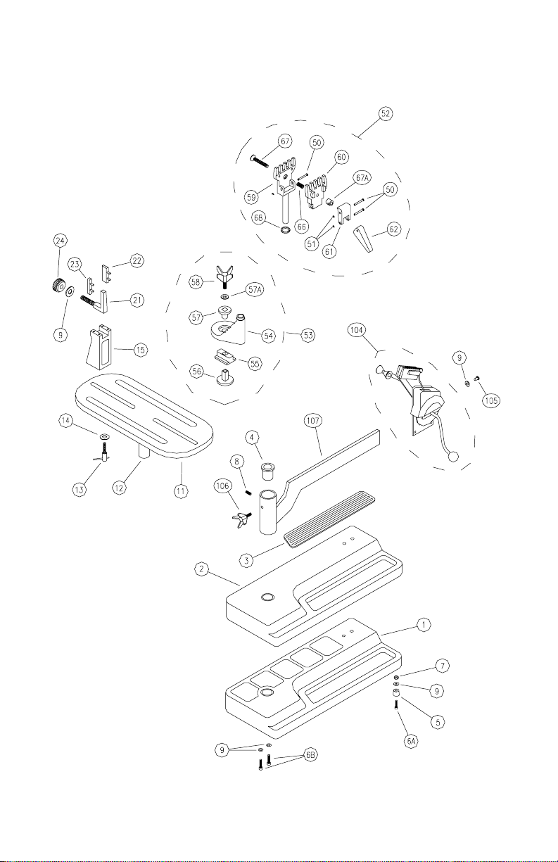
EXPLODED PARTS VIEW
16
Page 18

MOUNTING STAND PARTS
147
13
15
146
144
PART #
9
13
14
15
21
22
23
24
140
14
145
143
148
DESCRIPTION
WASHER - M8
POST LOCKING LEVER
WASHER - M10
SUPPORT POST
FRAME SUPPORT SLIDE
BADMINTON ADAPTER
TENNIS ADAPTER
SUPPORT SLIDE KNOB
MTNG. STAND TOP PLATE
24
122
21
PART #
141
142
143
144
145
146
147
148
140
141
142
9
22
23
DESCRIPTION
MTNG. STAND PAD
SUPPORT ARM - LEFT
SUPPORT ARM - RIGHT
SHOULDER SUPP. LOCK KNOB
SUPP. ARM RETURN SPRING
ARM ADJUSTMENT KNOB
ARM ADJUSTMENT SCREW
SHOULDER V-CLAMP
Page 19

NOTES
18
 Loading...