

Page 1
GAMMA Prog ression II / X-Stringer Floor Stand Assembly Instructions
Base Assembly
Remove the Lower Support Column from the carton. Align the holes in the Base Leg with the
matching holes in the Lower Support Column Post Plate. Loosely secure the Base Leg with one
button head cap screw, inserted through the Lower Support Column Post Plate, the hole in the leg
and threaded into the Bottom Plate. Repeat this procedure for the three remaining Base Legs.
Once all Base Legs are in place, securely tighten the cap screws. Place one lock washer and one
locking nut on each screw, where it protrudes from the Bottom Plate, and tighten securely with
the 10MM Box Wrench.
Support Column Assembly
Insert the Upper Support Column into the Lower Support Column / Base Leg assembly. Leave the
Upper Column extended about 1/2 of its length and lock in place with the two Column Height Lock
Screws located at the top of the Lower Column Support.
Attachment to Progression II Machine Base
Position the Progression II machine over the Flange Plate and align the four holes located in the center
of the machine base with the four center “P” holes of the flange plate. Secure the base of the machine
to the flange plate using the four feet from the machine base.
Attachment to X-Stringer X-Es and X-ST Machine Base
Position the X-Es or X-ST machine over the Flange Plate and align the attachment holes located in
the two slide brackets near the center of the machine base with the two “XA” holes of the flange
plate. Secure the base of the machine to the flange plate using two of the feet from the machine
base.
Attachment to X-Stringer X-6FC, X-6 and X-2 Machine Base
Remove the four feet from the base of the machine and loosen the set screws in the four slide
brackets located in the corners. Reposition the slide brackets to align the feet attachment holes with
the four corner “XB” holes located in the flange plate of the floor stand with the machine base
centered on the flange plate. Tighten the set screws in the slide brackets and secure the base of
the machine to the flange plate using the four feet.
Base Foot Height Adjustment
Each foot of the Floor Stand can be adjusted to level the stand on uneven surfaces. Remove the
Endcap from the leg to be adjusted, loosen the Base Foot Nut located inside of the leg tube with
the 10MM wrench. Adjust the foot to the desired level by turning the hex nut located between the
Base Foot and the the Leg Tube. Tighten the hex nut inside the leg tube to lock the foot in place.
Replace the Endcap.
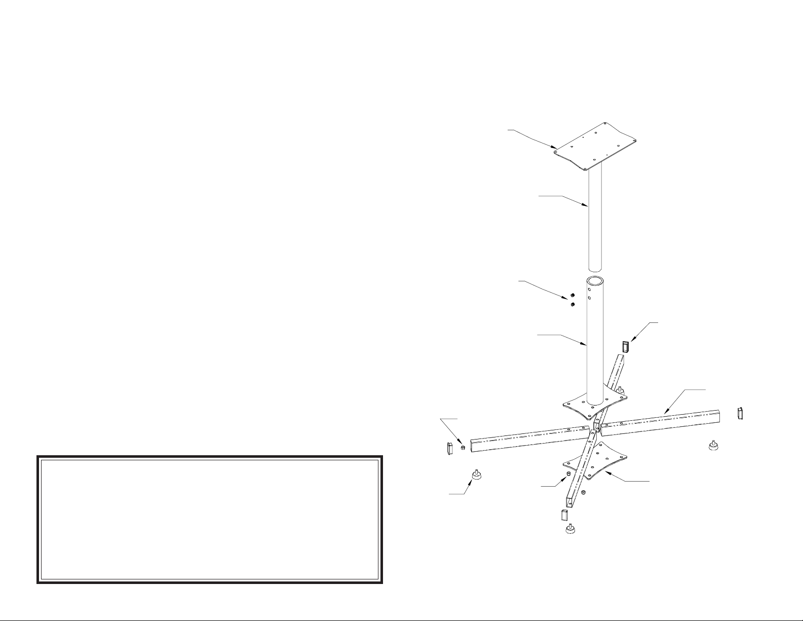
Upper Support Column
Flange Plate
Upper Support Column
Column Height Lock
Screws
Lower Support Column
Base Foot Nut
"XB"
"XA"
"P"
"XB"
"P"
"P"
"XB"
"XA"
"P"
"XB"
End Cap
Leg Tube
LIMITED WARRANTY
GAMMA SPORTS ("GAMMA") warrants to the original purchaser that the GAMMA Progression Floor Stand ("EQUIPMENT")
purchased is free from defects in materials and workmanship for a period of five (5) years from the date of original purchase. Should any
defects develop under normal use within the specified time periods, GAMMA will at its option, repair or replace the defective
EQUIPMENT provided it is returned to GAMMA prepaid at the purchaser's expense. This warranty does not apply to any damage or
defect caused by negligence, abuse, misuse, unauthorized alteration, shipping, handling, or wear and tear as a result of normal use.
GAMMA's obligation under this warranty is limited to repair or replacement of defective EQUIPMENT, and no one is authorized to
promise any other liability. GAMMA shall in no event be liable for any incidental or consequential damages.
To return defective EQUIPMENT, a return authorization (RA#) must be obtained from a GAMMA customer service representative by
calling 1-800-333-0337. The RA# must be marked on the outside of the shipping carton being returned. All returns must be shipped
prepaid by the customer to GAMMA. Please retain the original shipping carton and packing materials for any future shipments.
Base Foot
Lock Nut
Bottom Pla te
MPXFS Manual Issue 1 - 051804
 Loading...