

Page 1
PRO 100
STRINGING MACHINE
OO
WNER'S MANUWNER'S MANU
O
WNER'S MANU
OO
WNER'S MANUWNER'S MANU
Issue 3 - September 22, 1998Issue 3 - September 22, 1998
Issue 3 - September 22, 1998
Issue 3 - September 22, 1998Issue 3 - September 22, 1998
Copyright 1998 GAMMA Sports - All Rights Reserved
ALAL
AL
ALAL
Page 2

PRO 100
OWNER'S MANUAL
TABLE OF CONTENTSTABLE OF CONTENTS
TABLE OF CONTENTS
TABLE OF CONTENTSTABLE OF CONTENTS
PAGE 1 ............................................................................................WARRANTY
PAGE 2 .....................................................................ASSEMBLY INSTRUCTIONS
PAGE 5 ..................................................................... MOUNTING THE RACQUET
PAGE 6 ..........................................................................STRINGING THE FRAME
PAGE 9 ............................................................................................PARTS LIST
PAGE 10 ....................................................................... EXPLODED PARTS VIEW
LIMITED WARRANTYLIMITED WARRANTY
LIMITED WARRANTY
LIMITED WARRANTYLIMITED WARRANTY
GAMMA SPORTS ("GAMMA") warrants to the original purchaser that the GAMMA PROGRESSION stringing machine
("EQUIPMENT") purchased is free from defects in materials and workmanship for a period of five (5) years from the date of
original purchase for mechanical parts (excluding electrical parts and string clamps), and for a period of one (1) year from
the date of purchase for all electrical parts and string clamps. Should any defects develop under normal use within the
specified time periods, GAMMA will at its option, repair or replace the defective EQUIPMENT provided it is returned to GAMMA
prepaid at the purchaser's expense. This warranty does not apply to any damage or defect caused by negligence, abuse,
misuse, unauthorized alteration, shipping, handling, or part wear and tear as a result of normal use.
GAMMA's obligation under this warranty is limited to repair or replacement of defective EQUIPMENT, and no one is authorized
to promise any other liability. GAMMA shall in no event be liable for any incidental or consequential damages.
To return defective EQUIPMENT, a return authorization (RA#) must be obtained from a GAMMA customer service
representative by calling 1-800-333-0337. The RA# must be marked on the outside of the shipping carton being returned. All
returns must be shipped prepaid by the customer to GAMMA. Please retain the original shipping carton and packing materials
for any future shipments. GAMMA will not be responsible for machines which are not sent in the original undamaged
packaging.
1
Page 3
ASSEMBLY INSTRUCTIONS
Installing the Base Legs
A
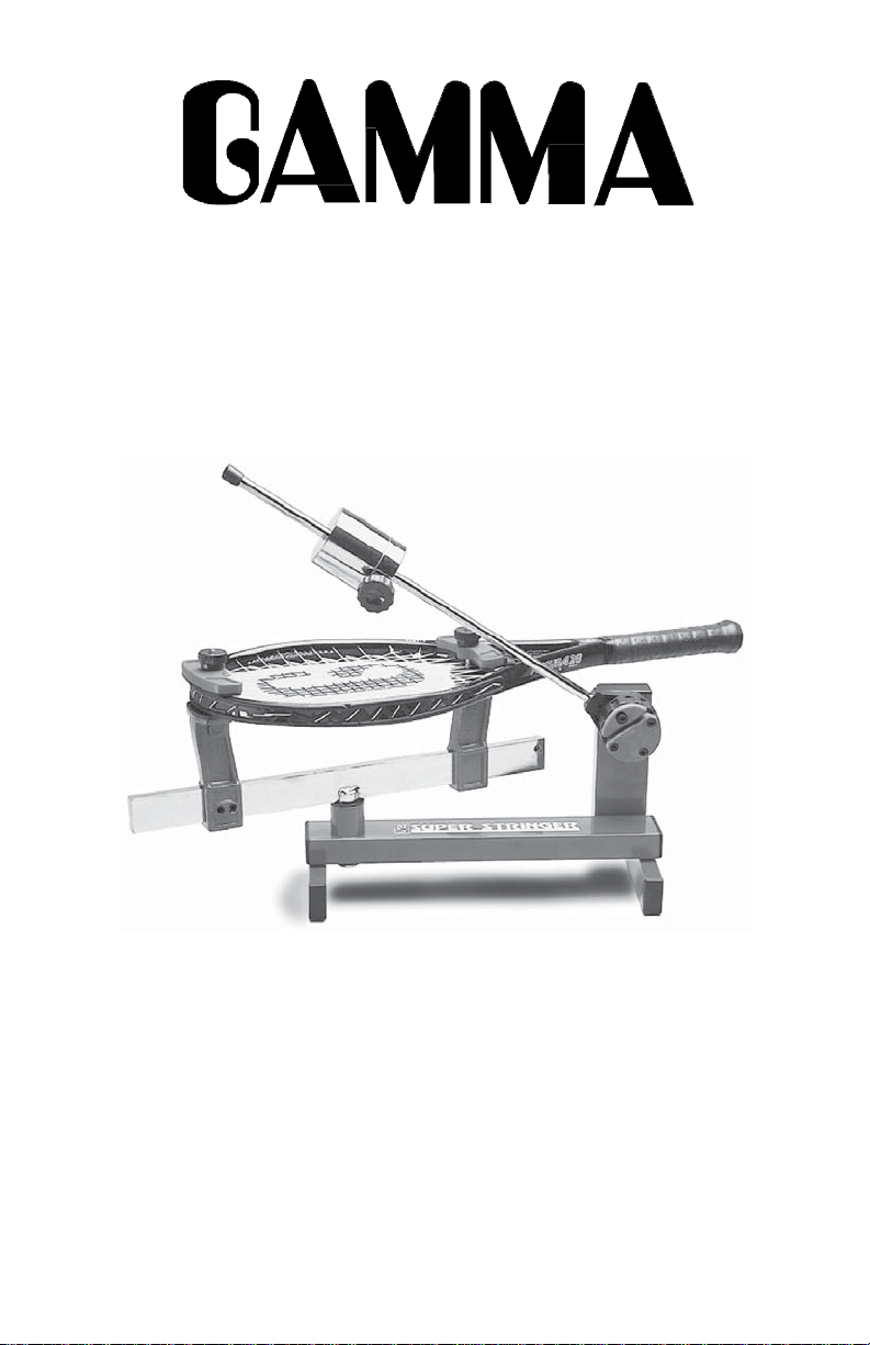
The PRO 100 is shipped with the legs separate from the base and requires assembly
before use.
Hole (A) in the machine base is the attaching
point for the base leg.
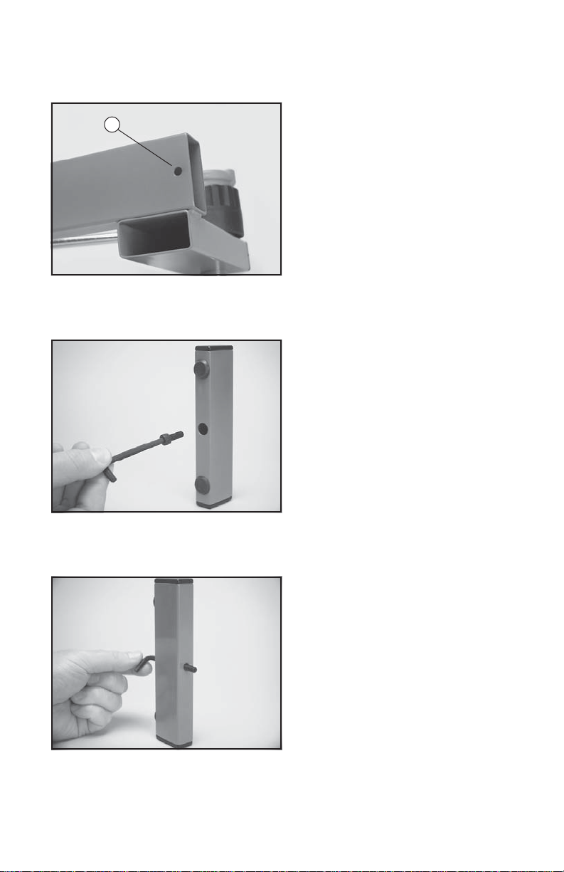
Place one screw onto the end of the 4mm
hex wrench. Carefully insert the screw
through the large hole in the bottom of the leg
and continue through the small hole at the
top of the leg.
While holding the leg, screw and wrench as
one unit, place the exposed end of the screw
through hole (A) in the machine base.
Place one washer over the exposed screw
end inside of the machine base. Thread one
locking nut onto the screw end.
2
Page 4
ASSEMBLY INSTRUCTIONS
Installing the Base Legs ( cont. )
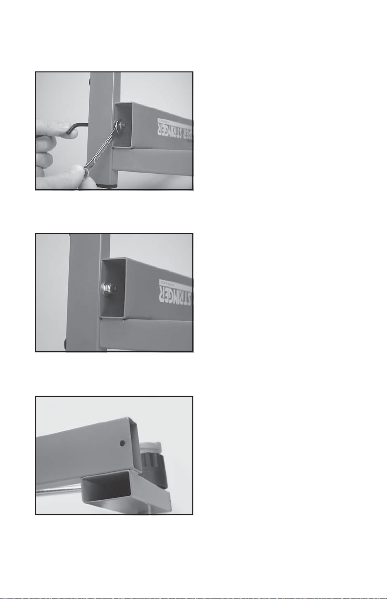
Using the included 10mm box wrench, securely tighten the locking nut.
The completed leg / base assembly.
Replace the base endcap making sure the
notched side of the endcap is aligned with
the leg attachment screw.
3
Page 5

ASSEMBLY INSTRUCTIONS
Installing the Turntable
Insert the turntable center post into the bushing assembly of the machine base.
Installing the Support posts
Slide each support post onto the end of the
turntable bar. The posts should be oriented
so as to angle away from the turntable center
post.
Installing the Drop Weight
Remove the endcap from the tension bar
and slide the drop weight onto the bar. The
weight should be oriented with the knob end
closest to the string winder. Replace the
endcap.
4
Page 6

MOUNTING THE RACQUET
Installing the Racquet Support Adapters
The PRO 100 is supplied with two styles of
Racquet Support Adapters. A thick profile
adapter for widebody racquets and a thin
profile adapter for conventional racquet
frames. The Adapters are also tapered, use
the highest side of the adapter that does not
interfere with the string grommet holes.
Adjusting the Frame Support Posts
Place the racquet frame over the center
posts and onto the frame support posts.
Loosen the locking screws on one support
post and slide the post in the appropriate
direction until the plastic adapter contacts
the frame. Securely tighten the locking
screws. Adjust the opposite post in the same
manner.
It is extremely important both plastic adapters are in contact with the frame to prevent
racquet damage.
Securing the Racquet
With the frame support posts properly adjusted, place the frame hold down plates
over the center screws and tighten the clamp
bar knobs securely. Do not overtighten the
knobs as frame damage may occur.
Note: Inverted throat racquet frames may
require the throat clamp plate to be rotated
180 degrees to match the frame.
5
Page 7

STRINGING THE FRAME
Starting the Main Strings
To begin stringing the main strings, count
the number of holes at the throat of the
frame, which will determine the starting point.
For racquets with 4 or 8 holes at the throat,
the main strings will begin at the head. For
racquets with 2 or 6 holes at the throat, the
main strings will begin at the throat.
Thread the two ends of the string through the
two center grommet holes at the head or
throat as determined in the previous step.
Route the strings through the opposite center
holes.
Clamping the First Main String
Thread one end of the string through the
adjacent grommet hole and pull excess by
hand. Clamp both the center and the adjacent string to each other on the inside of the
frame.
Pulling Tension
While holding the tension bar slightly above
horizontal, wrap the free string clockwise
around the gripper drum once and position
between the gripper jaw.
Gently turn the gripper clockwise while
squeezing the jaws together until all slack in
the string is removed.
Note: For proper operation, the string gripper
jaw must be in the position shown. The
tension in the string provides the clamping
force to the jaws.
6
Page 8

STRINGING THE FRAME
Pulling Tension
While holding the string gripper drum with
your hand, lift the tension bar to approx. 45
degree angle and let fall. If the tension bar
drops below horizontal, repeat the above
action until the bar comes to rest parallel to
the racquet. The set tension will be reached
when the bar rests horizontal.
If the bar comes to rest above horizontal,
release the string and re-pull tension.
Manually forcing the bar into the horizontal
position will greatly increase string tension
and may result in racquet damage.
Clamping the String
Clamp the tensioned string to the next adjacent string using the secong string clamp.
Release the tensioned string by raising the
tension arm.
Repeat the procedure for all of the remaining
main strings and tie off following the racquet
manufacturers recommendations.
Starting the Cross Strings
Follow the manufacturer's recommended
stringing pattern for one or two piece stringing. This will determine the starting point for
the cross strings. Weave the first two cross
strings and pull tension as per Step 3. Clamp
the cross strings as per Step 4.
7
Page 9

STRINGING THE FRAME
Finishing the String Job
Weave and tension the remaining cross
strings and tie off at the specified grommet
hole.
Remove the strung racquet from the Super
Stringer in the reverse order of mounting.
8
Page 10

PARTS LIST
PART #
4
24
25A
26
27
28
29
30A
31
32B
33B
34
36
37
42
43
44
45
46
47
48
49
50
51
DESCRIPTION
TURTABLE BUSHING
KNOB
SET SCREW
TENSION BAR CAP
DROP WEIGHT KNOB
FRONT WEIGHT
BACK WEIGHT
SET SCREW
STRING GRIPPER DRUM
UPPER GRIPPER JAW
LOWER GRIPPER JAW
RATCHET TEETH
GRIPPER JAW SPRING
CAP SCREW
FLOATING CLAMP ASMBLY
LEVER JAW
INNER JAW
KNOB JAW
LEVER
KNOB
SWING BOLT
RETURN SPRING
PIVOT PIN
RETAINING RING
PART #
78
79
82
82A
83
84
85
86A
87
88
89
92
93
94
95
161
162
163
69
70
72
73
98
DESCRIPTION
CLAMP PLATE
CLAMP PLATE PAD
FRM SUPP ADPTR - SHORT
FRM SUPP ADPTR - TALL
BASE
LEG
LEG CAP
WINDER STAND ENDCAP
RUBBER FEET
CAP SCREW
WASHER
TURNTABLE
SUPPORT POST
SUPPORT PIN
SUPPORT POST PAD
WINDER BEARING
GRIPPER PIVOT PIN - BS
PIVOT PIN RET. COLLAR
( NOT SHOWN )
HEX WRENCH / 3MM
T - HEX WRENCH / 5MM
PATHFINDER AWL
STRINGERS AWL
BOX WRENCH / 10MM
9
Page 11

EXPLODED PARTS VIEW
10
 Loading...