

Gamma 9900 Els Owner's Manual

9900 Els
STRINGING MACHINE
2 PT SC MOUNTING
OWNER’S MANUAL
Issue 1 - June 2015

9900 Els
OWNER’S MANUAL
TABLE OF CONTENTS
WARRANTY ................................................................................................PAGE 2
FEA TURES .................................................................................................PAGE 3
UNPACKING & ASSEMBLY INSTRUCTIONS ............................................PAGE 4
POWER CONNECTION & CONTROLS.....................................................PAGE 11
CONTROL PANEL FUNCTIONS AND FEATURES....................................PAGE 12
DISPLAY SCREEN.....................................................................................PAGE 13
MACHINE FUNCTIONS..... ......................................................................PAGE 14
STRING GRIPPER OPERATION .............................................................PAGE 19
MOUNTING THE FRAME ........................................................................ PAGE 20
STRINGING THE FRAME ........................................................................PAGE 21
STRING LENGTH METER .......................................................................PAGE 25
ADDITIONAL FEATURES..........................................................................PAGE 26
P A THFINDER A WL....................................................................................P AGE 27
MAINTENANCE & ADJUSTMENTS .........................................................PAGE 28
TROUBLESHOOTING TIPS .....................................................................PAGE 30
PARTS LIST ............................................................................................. PAGE 32
PARTS DRAWING ....................................................................................PAGE 33
LIMITED WARRANTY
GAMMA SPORTS warrants to the original purchaser that the 9900 Els stringing machine (“EQUIPMENT”) purchased is free
from defects in materials and workmanship for a period of fi ve (5) years from the date of original purchase for mechanical
parts (excluding electrical parts and string clamps), and for a period of one (1) year from the date of purchase for all electrical
parts and string clamps. Should any defects develop under normal use within the specifi ed time periods, GAMMA will at its
option, repair or replace the defective EQUIPMENT provided it is returned to GAMMA prepaid at the purchaser’s expense.
This warranty does not apply to any damage or defect caused by negligence, abuse, misuse, unauthorized alteration, shipping, handling, or part wear and tear as a result of normal use.
Routine maintenance, adjustment, and cleaning required to ensure proper operation are the responsibility of the purchaser
and are not covered under the terms of this warranty. These include, but are not limited to: String Clamp adjustment, as
described on page 28, Clamp Base adjustment, as described on page 28, and the cleaning procedures listed on page 29.
GAMMA’ s obligation under this warranty is limited to repair or replacement of defective EQUIPMENT , and no one is authorized
to promise any other liability. GAMMA shall in no event be liable for any incidental or consequential damages.
T o return defective EQUIPMENT , a return authorization (RA#) must be obtained from a GAMMA customer service representative. The RA# must be marked on the outside of the shipping carton being returned. All returns must be shipped prepaid by
the customer to GAMMA. Please retain the original shipping carton and packing materials for any future shipments. GAMMA
will not be responsible for machines which are not sent in the original undamaged packaging.
A GAMMA Care Service Plan is also available through GAMMA customer service, call 800.333.0337 for details.
2
MACHINE FEATURES
MACHINE FEATURES
Electric Constant Pull Tensioner with 11.0 to 90.0 lbs Tension
Range
Digital Tension Setting with LCD Display
Auto Start Quick Closing Linear String Gripper
Professional Two Point Self Centering Racquet Mounting
System- Accommodates All Racquets
Auto-Release Cam-Lock Swivel Base Clamps
4 Tooth Universal String Clamps
High Strength Extruded Aluminum Frame with Durable FRP
Finish and Convenient Deep Padded Tool Tray
Unique Turntable Clutch to Customize Rotation Friction
Convenient Foot Actuated Tensioner Switch
String Length Meter
3

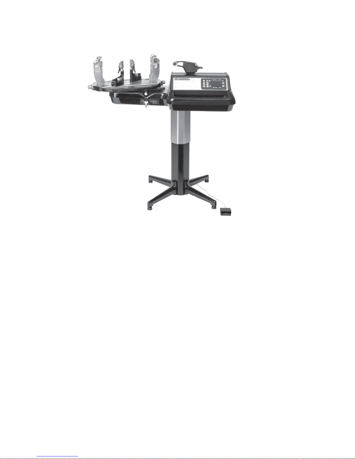
9900 Els
Unpacking Instructions & Contents
Instructions for Unpacking and Preparing for Assembly
The stringing machine is shipped in three cartons, a large master carton for the stringing
machine base with tensioner module and accessories, a medium carton for the turntable
and mounting system and a smaller carton for the fl oor stand post and base legs. Please
save the cartons and packing materials for possible shipments in the future. Gamma
Sports cannot be responsible for machines that are not returned, shipped in their original,
undamaged packaging. The tools you will need to assemble the machine are provided
with the machine. Due to the weight of the tensioner unit, you may need the assistance of
someone to help lift the tensioner unit out of the carton.
Once the cartons are opened, remove all inner cartons and check to be sure that all parts
are present and accounted for.
Contents of Electric Floor Stand (MMU3-20)
(1) Column Assembly
(4) Legs
(4) Leveling Feet
(4) M8 x 30 Flat Head Screws
(4) M8 x 35 Cap Screws
(4) M6 x 20 Cap Screws
(1) String Reel Holder (M8 Threaded Pin), (1) Knob, (8) Spacers, & (2) M8 Washers
Contents of Mounting System Carton (MMU3-28)
(1) Turntable Assembly w/ String Clamp Base and Mounting Stands w/ Frame Support
Slide, Side Supports, and Adapters
(2) String Clamps
(1) Package of spare plastic adapters for frame and mounting system supports
Contents of Machine Base Carton (MMU3-18)
(1) Stringer Assembly Unit w/ Tensioner Module
(1) Power Cord
(1) AC Adaptor
(1) Foot Pedal Tensioner Switch
(4) Rubber Feet for Table Top Use
(1) Wiring Harness for Electric Floor Stand Connection
(1) Stringing Tool Set - Includes 1 ea Diagonal Cutter, Bent Nose Pliers, Straight Nose
Pliers, Starting Clamp, Straight Awl & Pathfi nder Specialty A wl
(1) Tools for assembly and maintenance
4
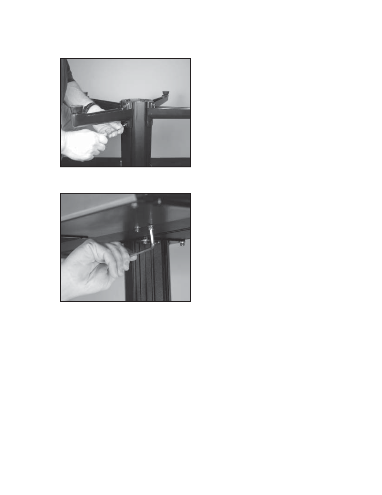
ASSEMBLY INSTRUCTIONS
Floor Stand Leg Assembly
The stringing machine uses a four leg fl oor
stand design. The legs must be assembled
to the Lower Column before use. Remove
all parts from the shipping carton to confi rm
that contents match the parts list.
Align the holes in the Leg Flange with the
matching holes in the Lower Column. Secure the leg with one M8x30 fl at head screw
through the upper hole, and one M8x35
socket head cap screw through the bottom
hole. Repeat this procedure for the three
remaining legs.
Mounting the Floor Stand to the
Machine Base
The Floor Stand can be mounted to the machine base by laying the machine on the fl oor
to align the 4 holes in the fl ange plate to the
machine base or by setting the machine on top
of the upright Floor Stand. Note: If mounting
the machine base to the top of the upright
Floor Stand use the help of an assistant to
balance the machine base while aligning
and tightening the four cap bolts. Orient the
fl oor stand to the machine so that the boss
for the string reel will be on the left side of
the machine base and the fl oor stand power
switch is at the rear side of the machine base.
CAUTION: To prevent damage to the string gripper, never lift or
move the machine by the string gripper.
5
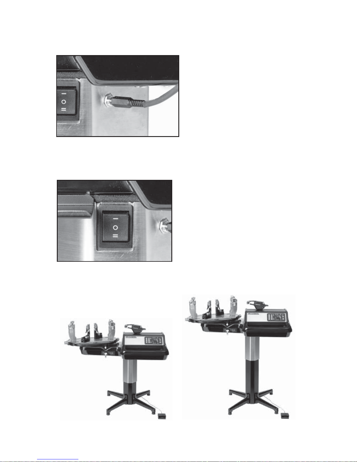
ASSEMBLY INSTRUCTIONS
Floor Stand Power Connection
Plug the Floor Stand power cord from bottom
left side of the tensioner housing into the
socket on the Floor Stand column.
Floor Stand Height Adjustment
The electric fl oor stand permits height adjust-
ments from 39” to 49”. The machine height
can be raised or lowered by depressing the
rocker switch Up or Down. When the desired
height is reached set the rocker switch to the
neutral position.
6
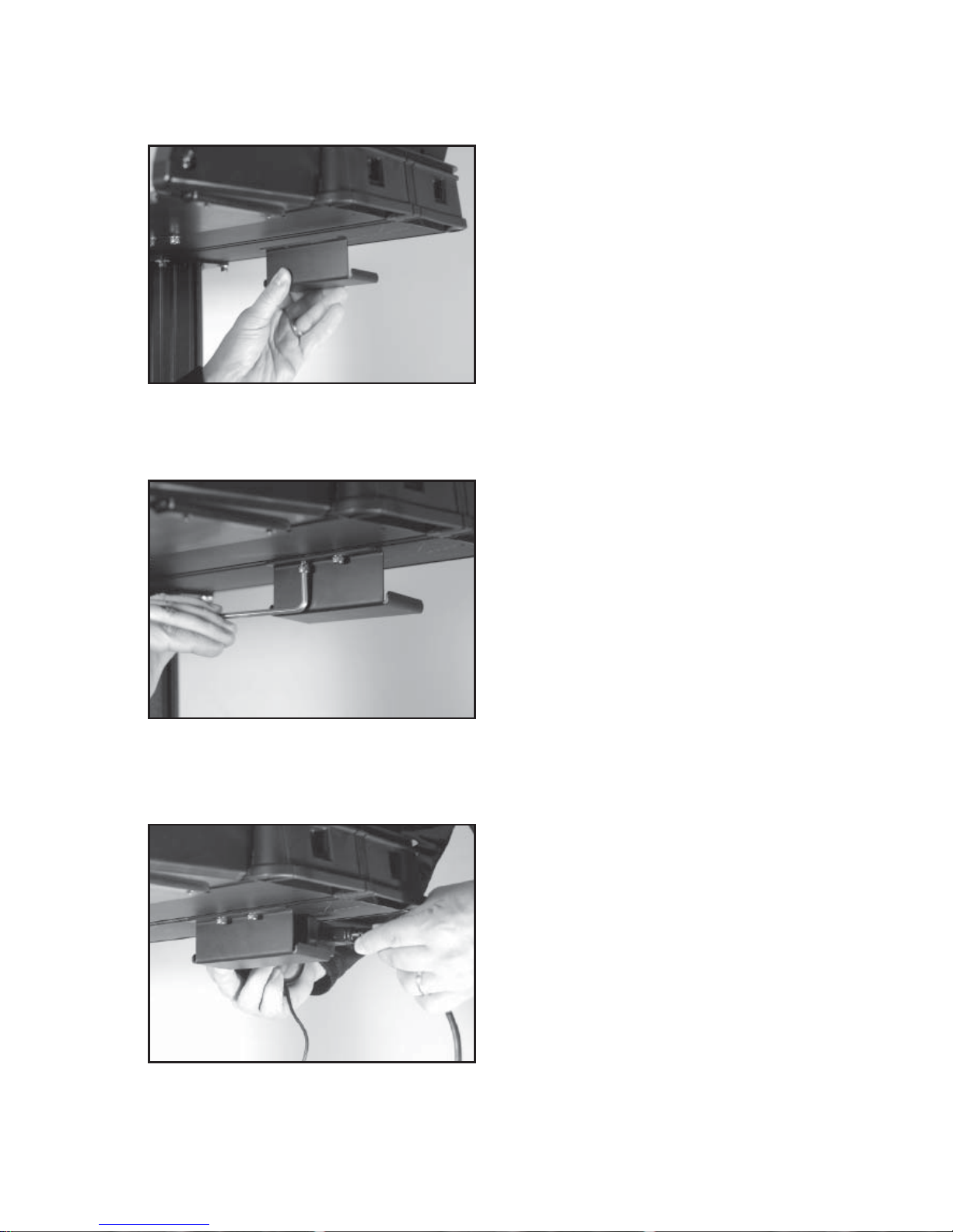
ASSEMBLY INSTRUCTIONS
AC Power Adapter Storage Shelf
The AC Power Adapter Storage Shelf provides a means to secure and protect the
power adapter by storing it safely under the
machine base. This will reduce a potential
tripping hazard as well as eliminate potential
damage to the AC Power Supply if laying
on the fl oor.
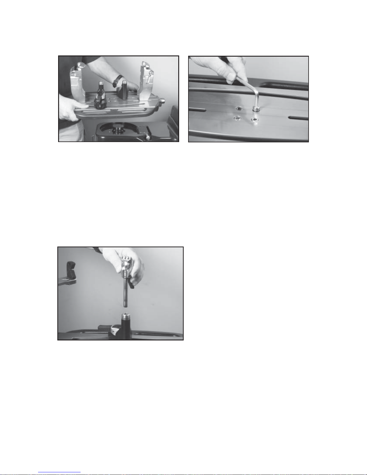
AC Power Adapter Storage Shelf
T o mount the Storage Shelf to the underside
of the base, align the holes in the storage
shelf bracket with the holes in the base. Use
a 6 mm hex wrench to tighten the two hex
head cap screws.
NOTE: T o avoid risk of damaging the threads
in the base, DO NOT OVERTIGHTEN.
AC Power Adapter Storage Shelf
Place the AC Power Adapter into the Storage
Shelf. Coil the pin connector cable and tuck
it between the top of the AC Power Adapter
and the machine base.
7
ASSEMBLY INSTRUCTIONS
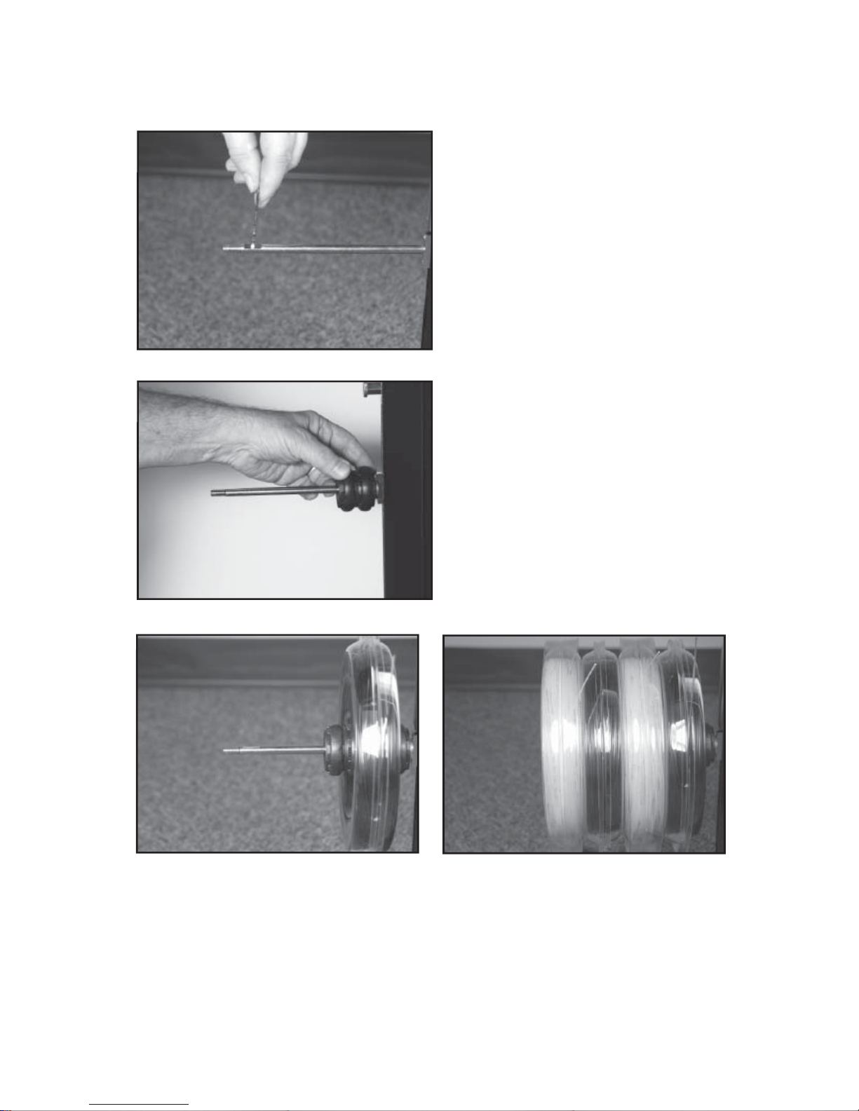
String Reel Installation
The String Reel Holder pin is an 8 mm rod
with threads on both ends and fl at surfaces
machined on one end. Thread the end of the
pin without the fl at surfaces into the threaded
boss on the right side of the Lower Column.
Using the M6 open end wrench positioned
on the fl at surfaces, securely tighten the pin
to the Lower Column.
The String Reel Holder can hold up to 4 reels
of string (depending on the size of the string
reel). Before placing the fi rst reel on the rod,
slide two spacers over the pin and slide them
to the connector on the Lower Column.
After the fi rst reel is placed onto the rod, place two spacers between each reel to provide
enough space between reels to allow them to turn freely without rubbing against one another.
(To provide a smooth feed to the String Length Meter , place the reels on the rod so the string
spools off the reel from the underside of the reel).
After the last reel is installed, place the two M8 washers on the pin and attach the threaded
knob to the end of the rod.
8
ASSEMBLY INSTRUCTIONS
Turntable and Mounting System Installation
To install the T urntable position the T urntable over the turntable pin and align the holes in the
turntable with the holes in the turntable pin. Insert the bolts through the holes in the turntable
and turntable pin and tighten with an M6 hex wrench.
STRING CLAMP INSTALLATION
String Clamp Installation
The post of the String Clamp and tube of
the String Clamp Base may be treated with
grease to provide protection against corrosion during shipping and while in storage.
Remove any excessive grease with a clean
cloth prior to use. The post and tube may
also be cleaned with isopropyl alcohol. After
this type of thorough cleaning, the post and
tube should be treated with a light coating of
machine oil to protect the surfaces against
corrosion and to ensure smooth operation.
9
POWER CONNECTION & CONTROLS
A
B
C
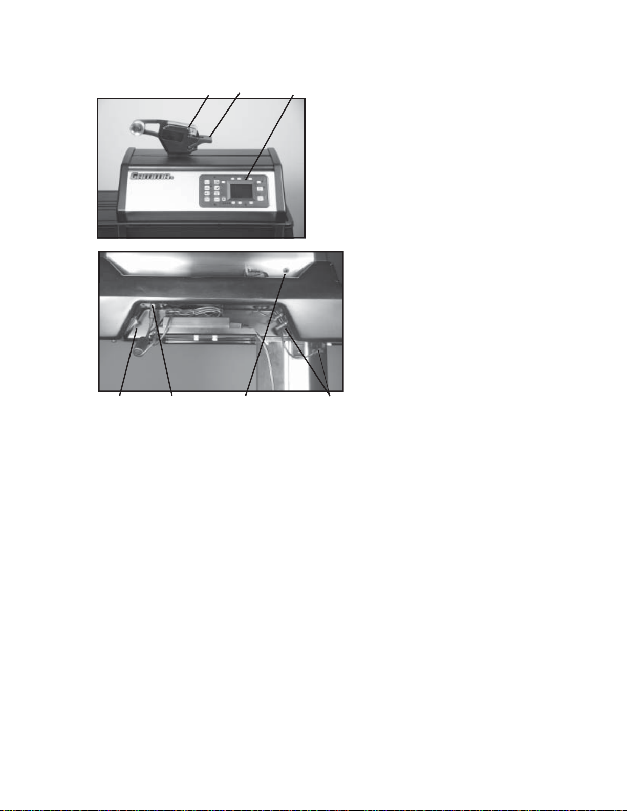
Front Panel Features
A - String Gripper
B - Tension Lever Switch
C - Control Panel with LCD Display
Back Panel Features
D - Power Switch
E - A/C Power Cord Socket
F - Foot Pedal Switch Socket
G - Floor Stand Power Socket
D
E
F
G
Instructions for Power Connection and Controls
CAUTION ! Before connecting to the power supply, check the voltage source that the
machine is being connected to. The acceptable range of input voltages for this machine is between 100 V and 240 V @ 50 to 60 Hz. If you have any questions regarding
the input voltage supply for your area, please ask your electric utility company.
To install the power cord, insert the female end of the power cord into the AC Adapter and
then insert the female end of the cord from the AC Adapter into the A/C Power Cord Socket
“E” located on the back side below the tensioner. Plug the male end of the power cord into
a grounded power outlet. When using extension cords, use grounded heavy duty extension
cords rated for 15 AMP service.
Insert one end of fl oor stand power cord into the Floor Stand Power Socket “F” and the
other end into the power socket next to the rocker switch on the top column of the fl oor
stand.
Connect the Foot Pedal Switch by inserting the male pin at the end of the Foot Pedal
Switch cord into the Foot Pedal Switch Socket “G” located on the back panel of the Tensioner.
Switch on the machine by pressing the On-Off Power Switch “D”. At start-up, the machine
will perform a self diagnostics check.
WARNING! FOR INDOOR USE ONLY.
NEVER OPEN UNIT WITH POWER CONNECTED.
CHILDREN SHOULD NEVER BE PERMITTED TO OPERATE THIS MACHINE
WITHOUT ADUL T SUPERVISION.
10
 Loading...