

Page 1
8500 Els
STRINGING MACHINE
OWNER'S MANUAL
Issue 1 - May 24, 2001
Copyright 2001 GAMMA Sports - All Rights Reserved
Page 2

8500 Els
Owner’s Manual
TABLE OF CONTENTS
INSIDE FRONT COVER .....................................................................WARRANTY
PAGE 1................................................................................................. FEATURES
PAGE 2................................................................ CONTENTS AND UNPACKING
PAGE 3..................................................................... ASSEMBLY INSTRUCTIONS
PAGE 9.................................................... POWER CONNECTIONS & CONTROL
PAGE 10................................ CONTROL PANEL FUNCTIONS AND FEATURES
PAGE 11................................................. STRING LENGTH METER OPERATION
PAGE 12........................................................... CAM-LOCK CLAMP OPERATION
PAGE 13.................................... STRING GRIPPER / TENSIONER OPERATION
PAGE 14......................................................................... MOUNTING THE FRAME
PAGE 15........................................................................ STRINGING THE FRAME
PAGE 16 ............................................................ PATHFINDER AWL OPERATION
PAGE 17................................................... MAINTENANCE AND ADJUSTMENTS
PAGE 18........................................ CARE AND CLEANING / BUZZER CONTROL
PAGE 19.................................................................... TROUBLE SHOOTING TIPS
PAGE 20.............................................................. PART NUMBERS AND LISTING
GAMMA SPORTS ("GAMMA") warrants to the original purchaser that the GAMMA stringing machine ("EQUIPMENT") purchased is free from
LIMITED WARRANTY
defects in materials and workmanship for a period of five (5) years from the date of original purchase for mechanical parts (excluding electronic
parts and string clamps), and for a period of one (1) year from the date of purchase for electronic parts and string clamps. Should any defects
develop under normal use within the specified time periods, GAMMA will at its option, repair or replace the defective EQUIPMENT provided it is
returned to GAMMA prepaid at the purchaser's expense. This warranty does not apply to any damage or defect caused by negligence, abuse,
misuse, unauthorized alteration, shipping, handling, or part wear and tear as a result of normal use.
Routine maintenance, adjustment, and cleaning required to ensure proper operation are the responsibility of the purchaser and are not covered
under the terms of this warranty. These include, but are not limited to: String Clamp adjustment, as described on page 12, Linear Gripper Plate
adjustment, as described on page 13, Cam-Lock Base adjustment, as described on page 17, Linear String Gripper adjustment, as described on
page 18, and cleaning of String Clamps, as described on page 18.
GAMMA's obligation under this warranty is limited to repair or replacement of defective EQUIPMENT, and no one is authorized to promise any
other liability. GAMMA shall in no event be liable for any incidental or consequential damages.
To return defective EQUIPMENT, a return authorization (RA#) must be obtained from a GAMMA customer service representative by calling 1-800333-0337. The RA# must be marked on the outside of the shipping carton being returned. All returns must be shipped prepaid by the customer
to GAMMA. Please retain the original shipping carton and packing materials for any future shipments.
Page 3
8500 Els
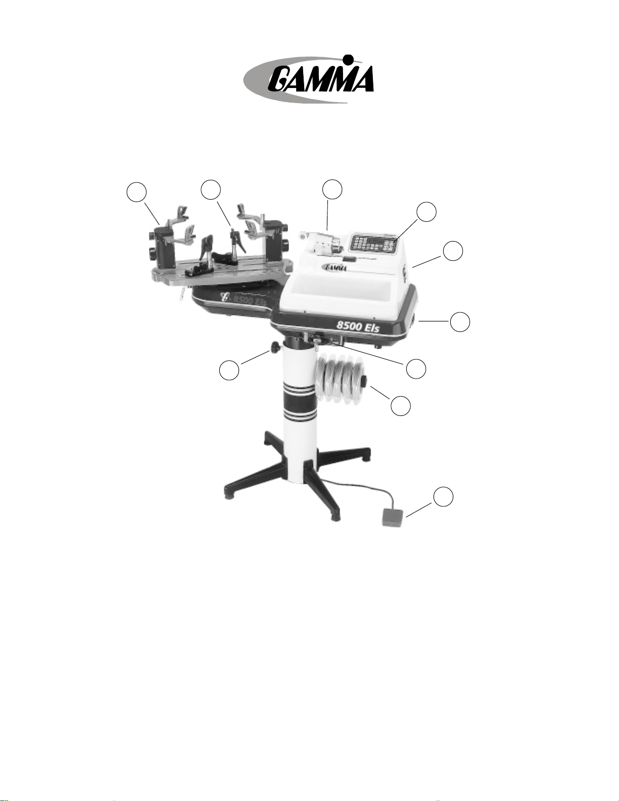
Key Product Features
5
6
9
1
2
8
10
4
3
1. Electric Constant Linear Pull String Tensioner w/ Diamond Coated String Gripper
(10-90 lbs tension range in 0.10 lbs increments)
2. Electronic Control Panel w/ Keypad, Knot, Prestretch, & String Length Functions
3. String Reel Holder
4. Electronic String Length Meter
5. 6 Point “Suspension” Mounting System (10 point support)
6. Dual Action, CAM-Lock, Swivel, String Clamps w/ Diamond Coating
7. Convenient Foot Actuated Tensioner Switch
8. Full Fiberglass Cover w/ Integrated Tool Trays (60 sq in of storage area)
9. Height Adjustable from 39” to 46” (can also be used on table top)
10. 110 V / 220 V Compatibility
1
7
Page 4

8500 Els
Unpacking Instructions & Contents
Instructions for Unpacking and Preparing for Assembly
The 8500 Els is shipped in two cartons, a large carton for the stringing machine and accessories and a smaller
carton for the post and base legs. Please save the cartons and packing materials for possible shipments in
the future. Gamma Sports cannot be responsible for machines that are not returned, shipped in their original,
undamaged packaging. The tools you will need to assemble the 8500 Els are provided with the machine. Due to
the weight of the tensioner unit, you may need the assistance of someone to help lift the tensioner unit out of the
carton.
Once the cartons are opened, remove all inner cartons and check to be sure that all parts are present and
accounted for.
Contents of Base & Leg Carton
(1) Lower Post
(2) Upper Post with Flange Plate
(4) Legs
(1) Locking Knob Screw
(4) M8 x 25 Flat Head Screws
(4) M8 x 30 Cap Screws
(1) String Reel Holder (M8 Threaded Pin), (1) Knob, (8) Spacers, & (2) M8 Washers
Contents of Large Master Carton (including accessory cartons packed inside)
(1) Stringer Assembly Unit w/ Tensioner Module and Turntable
(1) Power Cord w/ Ground Pin
(2) Suspension Mounting Stands w/ Frame Support Slide, Side Supports, and Adapters
(2) Mounting Stand Locking Levers w/ Washers
(2) String Clamp Heads
(2) Badminton Frame Support Slides Fitted w/ Plastic Adapter
(1) Package of Spare plastic adapters for mounting system supports (contains 16 pcs)
(1) Face Plate for String Length Meter & (4) Spare String Length Meter Clamp Pads
(4) Rubber Feet w/ Screws
(1) Foot Pedal Tensioner Switch
(1) Tool Kit (contains side cutter, bent nose pliers, needle nose pliers)
(1) Straight Stringers Awl & (1) Pathfinder Specialty Awl
(1) Starting Clamp
(2) Composite Badminton Floating Clamps
(1) 6 mm “T” Handle Hex Wrench
(1) 5 mm “T” Handle Hex Wrench
(1) 10 pc L-Hex Wrench Set
(2) Support Post Screws (M10)
(1) Open End Wrench – 6 mm
2
Page 5
Assembly Instructions
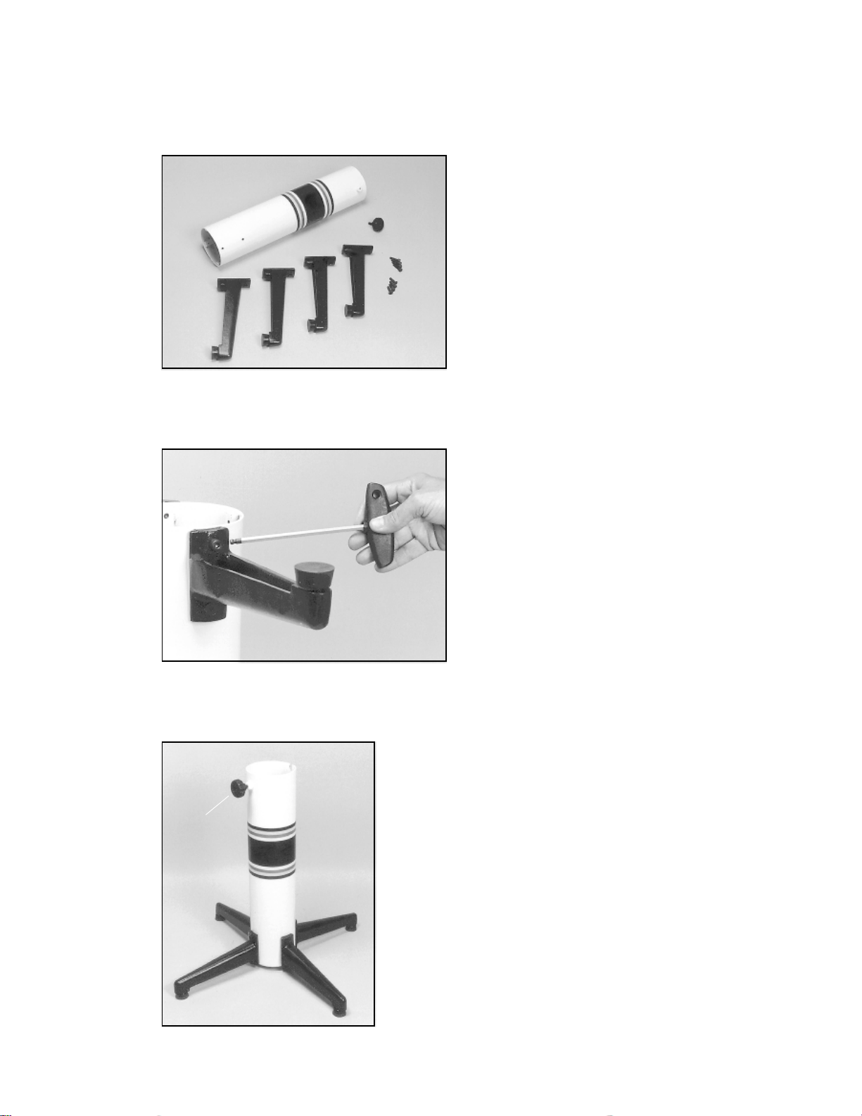
Base Leg Assembly
The stringing machine uses a four leg base design. The
legs must be assembled to the support post before use.
Remove the lower column support, the upper column
support, four (4) legs, four (4) socket head cap screws
and four (4) flat head cap screws from the small shipping
carton.
Base Leg Assembly (Cont.)
Align the holes in the leg flange with the matching holes
in the lower column support post. Secure the leg with one
FLAT HEAD cap screw through the upper hole, and one
SOCKET HEAD cap screw through the bottom hole.
Repeat this procedure for the three remaining legs.
“A”
Base Leg Assembly (Cont.)
To complete the base stand, screw the height adjustment locking knob
(“A”) into the side of the support column. The locking knob should not
protrude beyond the inside of the support column at this time.
3
Page 6
Assembly Instructions
Unpacking the Tensioner Assembly
The tensioner assembly is packed inside the inner
carton and is bolted to a sheet of wood with four (4) bolts
to prevent damage during shipment. Another sheet of
wood is bolted to the underside of the inner carton
through the first piece of wood. First locate the nuts
attached to the bolts that secure the outer piece of wood
to the inner piece of wood. Remove the nuts and with
assistance carefully lift the tensioner assembly from the
inner carton and lay it floor. To remove the inner piece of
wood from the base of the machine, raise each end and
remove the four (4) shipping bolts from the underside of
the wooden sheet. Note: Please retain the bolts, wood
and cartons for future shipment.
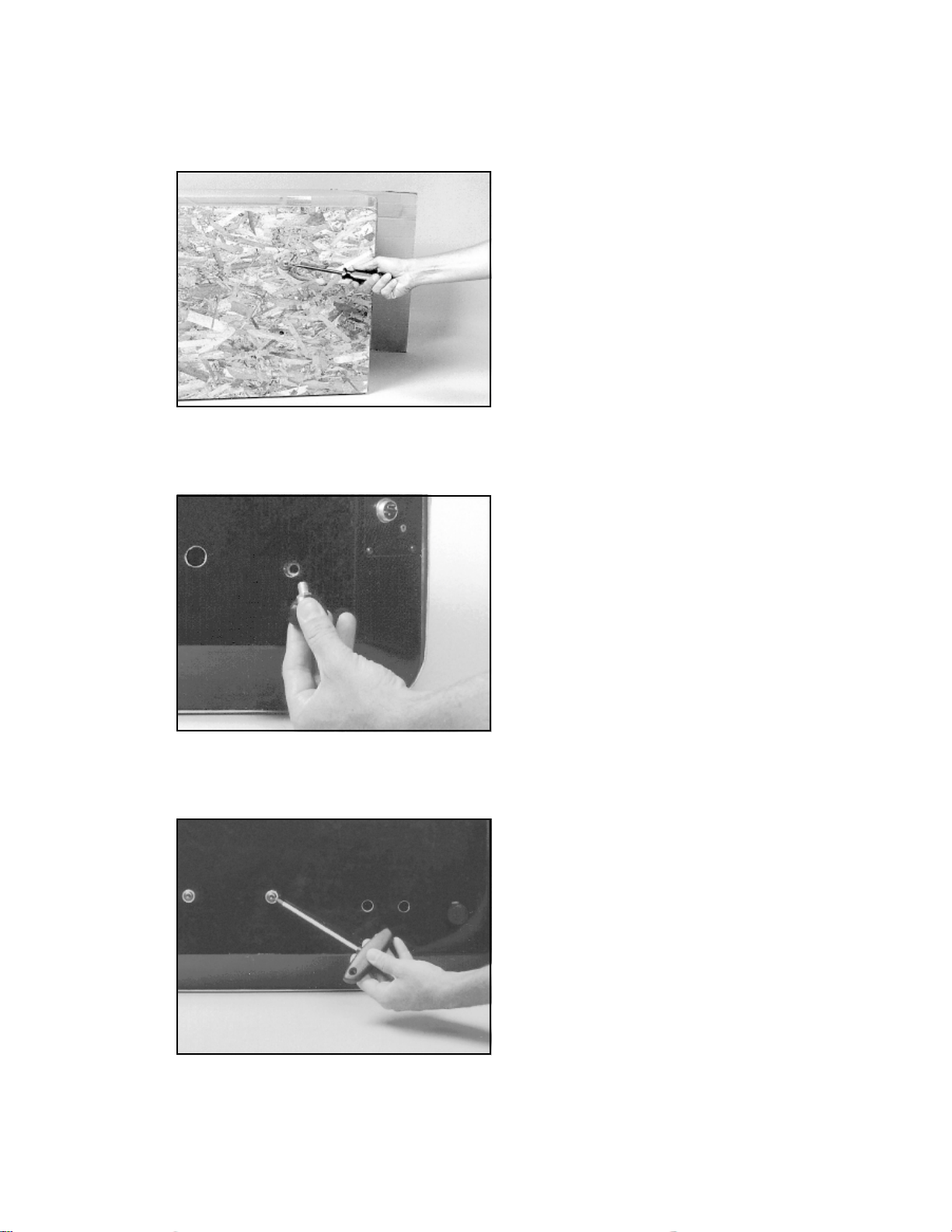
Foot Installation
CAUTION ! To maintain the alignment between the
fiberglass covers and the frame, it is very important
that the feet be installed before removing the four
center screws that attach the tensioner assembly to
the upper post flange.
To install the feet, tilt the tensioner back on its side and
screw the four feet into the holes at the corners of the
base.
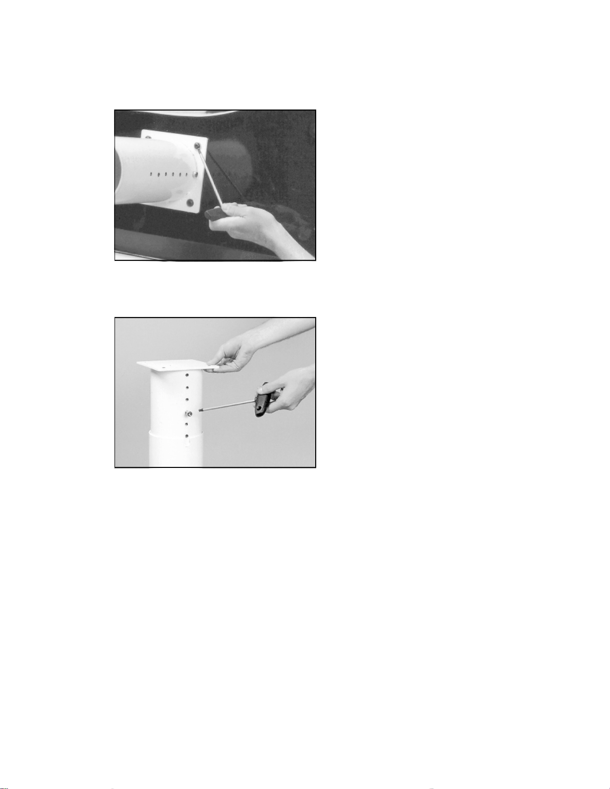
Stand Upper Post Installation
After installing the four corner feet, remove the four (4)
button head cap screws from the base of the assembly.
4
Page 7
Assembly Instructions
Stand Upper Post Installation (cont.)
With the height adjustment cap screw on the upper post
facing the right side of the tensioner, align the four (4)
holes in the upper post flange with the holes in the
tensioner base. Secure the flange to the base with the
four cap screws.
Height Adjustment
The height of the machine is adjustable from 39” to 46”.
To change the height, remove the socket head cap
screw from its current position and place it in the
appropriate hole to set the desired height of the machine.
5
Page 8

Assembly Instructions
Installing the Racquet Mounting System
Align the threaded hole in the bottom of the frame
support post with the slot in the turntable. Screw the lever
lock bolt with washer into the center hole located in the
bottom of the support post and loosely tighten. Position
the washer with the rounded edge toward the turntable.
Repeat procedure for the support post on the opposite
side of the turntable.
There are two guide pins located in the bottom of the
support post. The outer guide pin may be removed if
needed to provide additional separation space between
the mounting arms for mounting super oversize racquets.
Clamp Head Installation
The post of the string clamp head and the tube of the
string clamp base are treated with grease to provide
protection against corrosion during shipping. Remove
any excessive grease with a clean cloth prior to use. The
post and tube may also be cleaned with isopropyl
alcohol. After this type of thorough cleaning, the post
and tube should be treated with a light coating of
machine oil to protect the surfaces against corrosion and
to ensure smooth operation.
6
Page 9

String Reel Holder Installation
The string reel holder pin is an 8 mm rod with threads on
both ends, and flat surfaces machined on one end.
Thread the end of the pin without the flat surfaces into the
threaded boss on the right side of the lower column
support. Using the M6 open end wrench positioned on
the flat surfaces, securely tighten the pin to the lower
column support.
The string reel holder can hold up to 5 reels of string
(depending on the size of the string reel). Before placing
the first reel on the pin, slide two M8 washers over the pin
and slide them to the boss on the lower column support.
After the first reel is placed onto the pin, place two
spacers between each reel to provide enough space
between reels and allow them to turn freely without
rubbing against one another. (To provide a smooth feed
to the String Length Meter, place the reels on the pin so
the string spools off the reel from the underside of the
reel.)
After the last reel is installed, place the remaining
spacer(s) on the pin and attach the threaded knob to the
end of the pin.
7
Page 10

SLM Face Plate Installation
Remove the tape covering the opening on the front side
of the bottom cover to expose the string length meter.
Position the face plate assembly over the opening in the
bottom cover, and align the two countersunk end holes
of the face plate with the threaded attachment holes in
the front of the string length meter. With the two flat head
machine screws, secure the face plate assembly to the
string length meter.
To check for proper alignment, lift the top clamp of the
face plate assembly and insert a section of racquet
string at least 12 inches long into the entrance hole of the
face plate. Continue feeding the string section into the
string length meter, until it appears through the exit hole.
If the entrance or exit holes appear to be blocked, loosen
the attachment screws and adjust the position of the
face plate assembly until the section of string exits the
face plate. After the face plate is properly aligned,
tighten the flat head screws.
8
Page 11

Power Connection & Controls
Instructions for Power Connection (Refer to Figure 1)
CAUTION ! Before connecting to the power supply, check the voltage supply switch setting located on the
side panel as shown in Figure 1. To change from 110 volts service to 220 volt service simply slide the
switch fully to the top or to the bottom until “110V” or “220V” appears on the switch plate.
The acceptable range of input voltages for the “110 V” setting is between 110 V and 120 V @ 60 Hz and for
the “220 V” setting, between 220 V and 240 V @ 50 to 60 Hz. If you have any question regarding the input
voltage supply for your area, please ask your electric utility company.
To install the power cord, insert the female end of the power cord into the Power Cord Socket located on the side
panel and plug the male end into a grounded power outlet.
When using extension cords, use grounded heavy duty extension cords rated for 15 AMP service. To connect the
foot pedal switch, insert the 2 pin male connector located at the end of the foot pedal switch cord, into the two pin
receptacle located in the side panel. Tighten the connector with the sleeve nut located on the foot pedal switch
connector.
After checking to be certain that the machine is set for the correct input voltage, switch on the machine by
pressing the Lighted On-Off Power Switch on the side panel. At start-up, the LED will display a countdown from
“9.0” to “0.0” while the machine performs a self diagnostics check at start-up. The machine should be permitted
to warm-up for 10 minutes prior to stringing. After ten minutes, it is recommended that the “TEST” button be
pressed to self calibrate after warm-up.
“E” “A”
“F”
“G”
“B” “D”
“C”
Figure 1 - Side Panel Features
“A” - Lighted On-Off Power Switch
“B” - Power Cord Socket
“C” - Sliding Fuse Holder w/ Spare Fuse
“D” - 110V / 220V Switch
110
“E” - 2 Pin Foot Pedal Switch Socket
Figure 2 - Front Panel Features
“I”
“H”
“F” - Parallel Plate String Gripper
“G” - Tensioning Button Switch
“H” - Control Panel
“I” - LED Display
9
Page 12

Control Panel Functions and Features
Keypad - Used to enter
tension settings
Tension Index Buttons - Changes tension setting
in +/- 1.0 or 0.1 Lb or Kg increments. Holding the
button down will scroll the tension setting values
up or down. Tension settings entered with the
tension index buttons are placed into temporary
memory setting “0”.
Single Digit (0-4)
Memory LED Display
Three Digit (XX.X) Tension Settings or String
Length LED Display
Release Button - Returns gripper to starting
position and releases tension
Memory Button - Indexes from 4 preset tension
settings that can be stored in memory. Settings are
retained even if machine is turned off. Each press of
the button indexes to the next memory setting.
Memory settings 1-4 must be entered using the
keypad followed by pressing the “ENT” button.
Clear Button - Clears display to enter a new
tension
Test Function - Performs internal calibration
check. Press and hold for 5 seconds until the
winder reverses and performs an internal
diagnostic check, such as the one performed at
start-up.
Lbs/Kgs Button - Changes tension
display from Lbs to Kgs. Each press of the button
toggles back and forth between Lbs and Kgs
Pre-Stretch Function - Pulls string 10% or 20%
over the tension setting (up to 90 lbs / 40.8 kgs),
releases the string, and repulls to the tension
setting. Each press of the button toggles between
10%, 20% or no pre-stretch.
Enter Button - Confirms tension setting when entered
on keypad (display flashes when tensions are keyed
in with the keypad until this button is pressed)
Knot Function - Increases pulling tension by 10%
over the setting value (max 90 lbs / 40.8 kgs) for one
pull. During pull the Memory LED flashes to indicate
that the Knot function is enabled.
Speed Button - Changes pulling speed of winder
from Fast to Slow. Slow speed is recommended
for low stretch strings, such as Kevlar. Each press
of the button toggles back and forth between Fast
and Slow speed.
String Length Meter Button - Enables string
length meter function. Each press of the button
toggles back and forth between Meters and Feet
measurement. To switch back to tensioning
function, press the “Lbs/Kgs” button.
10
Page 13

String Length Meter Operation
To enable the String Length Meter (SLM) function, press
the String Length function key on the keypad. When the
String Length button is pressed, one of the Red LED
indicators below “M” or “FT” will light up to indicate that
the SLM function is enabled. Pressing the String Length
button will toggle between “M” and “FT” to set the
measurement units for either Meters (“M”) or Feet (“FT”).
Measurements are displayed in 0.1 increments.
To measure out a length of string from a reel (sets can
also be measured) insert one end of the string through
the string guide grommet (from the backside). While
lifting the clamp pad, insert the string through the
entrance hole of the face plate until it appears at the exit
hole and release the clamp pad. (The clamp pads will
prevent debris from entering the SLM.)
When the end of the string appears out of the exit hole,
press the “C” button on the keypad to “Zero” the SLM,
and the length of string measured will be measured from
the point on the string located at the edge of the exit
hole. Pull the end of the string in a slow steady fashion
and the SLM will begin measuring the length of string
pulled and indicate the measurement on the LED display. When the desired length of string is measured, cut
the string at the exit hole.
NOTE : When reaching the end of a length of string,
pull the string through very slowly to avoid inaccurate string measurement. The string length meter was
designed to measure strings between 1.10 mm (18 ga)
and 1.45 mm (15 ga) at an accuracy of +/- 0.3% of the
indicated value and +/- 2 inches (50 mm) absolute.
When measuring strings smaller than 1.10 mm (such
indicated value (up to 6” short in 40 ft) and +/- 2 inches (50 mm) absolute.
as badminton strings) the error will be -2.5% of the
11
Page 14

Cam-Lock Clamp Operation
Clamp Head Operation
To clamp a string, lift the clamp head and place the string
between the jaws and depress the clamp head lever to
secure the string. The clamping pressure applied to the
string should be adjusted to provide sufficient pressure
to secure the string when subjected to the desired pulling
tension. The diamond coated gripper plates provide for
increased friction between the clamps and the string to
allow for reduced clamping pressure while securing and
holding the string under tension.
CAM-LOCK Clamp Base Operation
Rotate the Base Locking Lever clockwise to secure the
clamp base to the turntable.
Reverse the clamping procedure to unlock the string
clamp. The Locking Lever is spring loaded to assist the
unlocking of the clamp base.
The Locking Lever should be tightened enough to prevent clamp base slippage on the turntable, when the
desired tension is placed on the string. To go from the
loose position to the clamped position and back, generally requires the travel permitted by the clamp base. If
the travel is not sufficient to allow smooth operation of,
adjust the Clamp Base as outlined in the Clamp Base
Adjustment section.
Clamp Head Adjustment
The clamp heads will need minor adjustments according to what string type, construction, and gauge you are
using.
To adjust the gap (clamping pressure) between the
clamp jaws, insert the string through the racquet as if
you were beginning the main strings. Clamp the strings
and pull tension. If the string slips through the jaws of the
clamp, tighten the clamp by compressing the clamp
jaws together by hand while turning the Adjustment
Adjustment
Knob
Note: The string clamps supplied with your stringing machine can accomodate tight string patterns such as
badminton. Depending on the string pattern, the clamp may spread the strings slightly which will not compromise the
quality of the string job.
Knob, in the clockwise direction. If the clamp leaves
impressions or damages the string, it may be excessively tight and should be adjusted by turning the hex
screw counter clockwise to open the gap between the
jaws. The clamp jaws must be cleaned periodically to be
free from dirt and any residue for them to grip properly.
12
Page 15

String Gripper Operation
String Gripper Operation
To insert a string into the linear string gripper, wrap the
free end of the string clockwise around the roller guide
and insert the string between the diamond dust coated
string gripper plates. Excessive slack in the string
should be removed before applying tension. Pull the
string perpendicular to the gripper plates and begin
tensioning. As tension is applied, the grippers will
engage to hold the string. For adjustment of the parallel
plates, see “Setting the Gripper Plate Spacing” on page
18.
CAUTION ! CHILDREN SHOULD NEVER BE PERMITTED TO OPERATE THIS MACHINE WITHOUT
ADULT SUPERVISION.
Tensioner Operation
Tensioning
Button
Setting the String Tension
String tensions may be entered using the keypad and
storing the settings into one of four memory storage
settings (See section on Control panel Functions and
features) or by using the tension index buttons. While the
tension setting is entered, the value displayed will be
flashing until the “ENT” button is pressed, indicating that
the tension setting is accepted.
Tensioning a String
After the string in inserted into the parallel plate
grippers, press the tensioning button switch on the
front panel of the machine, or press the foot pedal
switch to activate the tensioner. The using the fast
pulling speed (see section on Control Panel Functions
and features) the tensioner will start pulling at full
speed and then slow down as the tension in the string
approaches the tension setting. When the tension in
the string reaches the tension setting, the LED display
will begin to flash, and the string will be ready to clamp
off. In the event that the tensioner reaches the end of
its travel and the string is not yet at tension, the buzzer
will sound. Clamp off the string and repeat the tensioning
process. If one of the keys on the control panel are
accidently pressed while tensioning a string, the
tensioner will automatically reverse and release the
string being tensioned.
13
Page 16

Mounting the Frame
Adjusting the Frame Support Posts
Place the racquet frame over the center support slide
and onto the frame support. Loosen the lever lock bolt on
one support post. Slide the post outward until the center
support of the racquet support slide is positioned near
the inside surface of the racquet frame. Securely tighten
the lever lock bolt.
Adjust the opposite post using the same procedure.
Caution: To avoid racquet damage, the support slide
should not contact the racquet prior to fixing the support
posts.
Shoulder Support Adjustment
The shoulder supports are adjustable to provide support
to the racquet frame. Loosen the knurled knob at the
bottom of the shoulder support and swivel the support so
that the pads will contact the frame squarely when the
arms are closed against the racquet. Should the shoulder supports block string holes, adjust the position of the
racquet between the arms until the shoulder supports
contact the racquet between grommet holes.
Securing the Shoulder Supports
Secure the racquet frame with the shoulder supports by
rotating the large adjustment knobs on the outside of the
support post assemblies clockwise. Adjust the supports
until firm contact is made between the shoulder supports
and the frame.
The tear drop shaped holes towards the back of the
shoulder supports are handy for holding the loose
end of the string while pulling the string through the
racquet. Simply insert the loose end into the tear
drop shaped holes and slide the string into the point
of the hole.
14
Page 17

Mounting the Frame
Support Slide Adjustment
Once the frame support posts are secured, lightly tighten
the support slides by turning the knobs on the outside of
the slides clockwise. Adjust the slides in equal increments until slight resistance is felt.
Apply a final adjustment to all racquet support points
until the racquet is firmly secured in the mounting
system.
Should the frame supports lose contact with the frame
while stringing, they should be adjusted, as needed, to
maintain contact with the frame.
Stringing the Frame
Installing the Main Strings
To begin stringing the main strings, insert the two ends
of the string through the two center holes at the appropriate end of the frame and continue through the center
holes on the opposite end of the racquet.
Secure one of the strings using a string clamp and insert
the free end into the string gripper.
When tension is applied to the string, clamp off the
tensioned section of string, release string from tensioner,
and proceed to thread string into next sets of holes. After
the last main strings are pulled, tie-off the strings at the
appropriate hole specified by the racquet manufacturer.
Installing the Cross Strings
Weave the cross strings over and under the main strings
being careful to alternate the weave direction of each
consecutive cross string so as to be opposite of the
previously installed cross string.
Once the final cross string is tensioned and clamped, tie
off at the appropriate hole specified by the racquet
manufacturer.
Remove the strung racquet by loosening the shoulder
supports and support slides in small increments until the
racquet is free from the mounting system.
15
Page 18

Pathfinder Awl Operation
The machine includes the new Pathfinder stringing awl
which creates a pathway between or around strings to
make inserting a string through tight grommets easier
and quicker.
Insert the awl through the grommet hole in the same
manner as for traditional awls. The Pathfinder awl must
be in the closed position before insertion.
Once the awl is inserted, pull the handle of the awl
outward while holding the tip section in place, leaving
the outer sheath in the grommet hole.
Insert the end of the string into the center of the sheath.
While holding pressure on the string, slowly pull the
sheath out of the grommet hole to leave the end of the
string exposed.
16
Page 19

Tensioner Calibration
Each stringing machine has been checked and calibrated at the factory using accurate load sensing devices to
ensure that the machine pulls at the correct tension. The tension is then controlled by the pre-set factory settings
of the electronics. However, if you suspect that your machine is not pulling at the correct tension, or if you would
like to check the pulling tension using a tension calibration device, you may do so.
Most tension calibrators (such as a Gamma Tension Calibrator) function by inserting a string from the end of the
calibrator into a string clamp, and pulling on the string located on the opposite end of the calibrator. The tension
measured by the calibration device will then display the tension being applied to the calibrator by the machine.
With the machine set for the fast pulling speed, and the tension set at 20 lbs., place the string from one end of the
calibrator (preferrably equipped with synthetic string) into a string clamp. Place the opposite end into the string
gripper and apply tension. If the tension indicated on the calibrator does not match the tension setting, release the
string and remove it from the gripper.
Press and hold the “Test” button on the control panel for 5 seconds and release it when the tension display
starts its countdown and the machine performs its own self diagnostic test. After the display returns to
the preset value, recheck the pulling tension using the tension calibrator at both 20 and 60 lbs.
can be externally calibrated by up to +/- 5 lbs from the factory settings. If the difference between the measurement
from the calibrator and the tension setting is more than 5 lbs. call the machine service department of GAMMA Sports
at 1-800-333-0337 for assistance.
In the event that the measurement from the calibrator does not match the tension setting, the machine
To calibrate the machine externally, set the machine for a pulling tension of 40 lbs. With the
calibrator attached, press and hold the “TEST” button until a flashing “9” appears on the display.
Press the “+0.1” or “-0.1” buttons, to match the display value to the calibrator value. Press “ENT”
to save the calibration settings.
Cam-Lock Clamp Base Adjustment
If the bases of the Cam-Lock clamps slip on the glide bars, the base
locking levers may need adjustment.
Remove the plastic cap by pulling straight up on the edges of the cap.
Line up the large hole in the clamp base with the smaller hole in the
locking cone as shown.
Insert the 3mm hex wrench through the holes and into the screw located
in the base. Rotate the wrench clockwise to tighten the clamp and
decrease the base locking lever travel. Rotate the wrench counterclockwise to loosen the clamp and increase the base locking lever travel.
17
Page 20

Setting the Gripper Plate Spacing
The parallel plates of the string gripper are adjustable to
accomodate varying string gauges and types of string. If
the string slips through the gripper plates while pulling
tension, rotate the gripper adjustment screw counterclockwise. If the string is damaged while pulling tension,
rotate the gripper adjustment screw clockwise. The
gripper is properly adjusted when there is enough pressure to securely grip the string without causing damage
to the string.
Gripper Adjustment
Screw
Cleaning Instructions for String Clamps
To thoroughly clean the diamond coated surfaces of the
clamp heads, remove the adjustment knob screw, lever
plate, and compression spring to expose the inside
surfaces of the clamps. Using the cleaning stone provided with your machine (you can also use a small tooth
brush or a sharpening stone for knives), scrub the
diamond coated plates until all debris is removed. Clean
any dust or residue with a damp cloth and re-assemble
the clamp head.
Buzzer Control
The stringing machine is equipped with a buzzer function that sounds when any key or button is pressed; it also sounds
an intermittent warning when the tensioner has pulled a string to the end of its travel and is not yet at tension, or if there
is an internal error in the machine. The buzzer can, however, be disabled for normal key / button presses. To toggle
between buzzer enabled / buzzer disabled modes:
Turn the machine on; while the display is counting down from 9 to 0, press the clear (C) and enter
(ENT) keys together. The machine will switch modes, and the changes will remain in effect until
the user toggles modes again.
NOTE: In disabled mode, the buzzer will still sound if the tensioner has pulled a string to the end of its travel and is
not yet at tension, or if there is an internal error in the machine. This is meant to alert the user of a problem, and should
never be disabled.
18
Page 21

T roubleshooting Tips
PROBLEM SOLUTION
String slips in clamps
String slips in gripper • Adjust gripper adjustment screw
String clamp slips on base • Adjust base locking lever
String Length Meter measures inconsistently • Contact Gamma Sports Machine Service
Electrical system does not function
To check fuse, remove the power cord and pull the fuse holder straight out. Remove the fuse from the clips
and examine it. If it is burned out, replace it with the spare fuse located in the holder and replace the fuse
holder in its socket. Supply power to the machine and check for proper operation. If problems persist, contact
Gamma Sports Customer Service at 1-800-333-0337.
• Adjust gap between jaws
• Clean clamp jaws
• Clean base of clamp and turntable glide bars
Department for SLM Cleaning Procedure
• Check power source / voltage setting
• Check power cord connection
• Check fuse
• Call Gamma Sports customer service
Self Diagnostics
The electronics of the machine are designed to provide self diagnostic trouble shooting information, if parts of
the machine do not function normally. When this occurs, error codes will appear on the display. A summary of
the error codes and corrective actions that should be taken are provided below.
Code Corrective Action
C01
C02
C06 • Call GAMMA Sports for assistance
C07 • Check for loose power connection at AC socket or wall outlet
C09 • Check that voltage setting for machine is correct
To reset the machine after an error code appears, press the Clear (“C”) button on the control panel. If the error
code disappears, resume stringing as normal. If the error code re-appears, corrective action needs to be taken.
For assistance, call the machine repair department of GAMMA Sports at 1-800-333-0337.
• Check wiring to return microswitch on motor and PC board
• Check return microswitch on motor shaft
• Call GAMMA Sports for assistance
• Check that string is still not engaged in gripper after gripper returns
• Call GAMMA Sports for assistance
• Call GAMMA Sports for assistance
19
Page 22

8500 Els
Parts Summary
173
199
195
194
178
204
205
209
Inside Cover
248
218
Inside Cover
203
217
219
115
127
106
221
223
180
222
249
208
211
210
212
247
250
101
102
103
128
22A
21B
134
133
23A
114
132
21A
135
122A
14
20
6B
139
9
13
136
121
22A
131
22B 23A
23B
Page 23

8500 Els
Parts List
Part # Description
6B Cap Screw - M8 x 30
9 Washer - M8
13 Locking Lever
14 Washer - M10
21A Frame Support Slide SM Tennis
21B Frame Support Slide SM Badminton
22A Badminton/Squash Throat Adapter
22B Badminton Head Adapter
23A Tennis/Squash/Racquetball
Standard Adapter
23B Tennis Fan/Tapered Pattern Adapter
101 AC Power Cord
102 Fuse Holder Cap
103 Fuse
106 Locking Knob Screw
114 Short Leg
115 Flat Head Cap Screw -M8 x 25
121 Leveling Foot
122A Shoulder Support Pads - Black
127 Flanged Upper Support Column
128 FRP Base Foot
131 Foot Pedal Switch
132 Mounting Arm Adj. Knob SM
133 Support Slide Adj. Screw SM
134 Suspension Mounting Arms
135 Shoulder Support Adj. Knob SM
136 Shoulder Support SM
139 Shoulder Support Bushing
173 Turntable Glide Bar/12.5mm
178 Glide Bar SST
180 Comp Fixed Clamp Thin
194 TT Brake Pad
195 TT Brake Pad Flat Head Screw
199 Flanged TT Pin
203 Flanged TT Pin Cap Screw
204 Cam Lock Base/Glide Bar Assy
205 Cam Lock Clamp Base
208 Lower Column (w/RH Reel Hold)
209 TT Brake Lever
210 Reel Holder Bolt
211 Reel Holder Spacer
212 Reel Holder Knob
Part # Description
217 8500 Lower Cover
218 8500 Frame Assy
219 8500 Transformer Set (117/230)
221 String Length Meter Cover
222 String Length Meter Clamp Pads
223 String Length Meter
247 8500 Els Tensioner Module
248 8500 Top Cover
249 8500 Upper Tray Pad
250 8500 Lower Tray Pad
SP ARE PARTS & TOOLS
Part # Description
72 Pathfinder Guiding Awl
73 Stringer’s Awl
109 Needle Nose Pliers
110 Bent Nose Pliers
169 Bad. Flying Clamp Set
170 M10x35 Cap Screw for SM
171 Cutting Pliers
194 TT Brake Pad
206 13 mm Open End Wrench
221 String Length Meter Clamp Pads
224 6 mm Open End Wrench
230 Gripper/Clamp Cleaning Stone
251 Long Hex Wrench Set (9 pcs)
21
 Loading...