

Gamma 7900 Els, 8900 Els Owner's Manual
7900 Els
STRINGING MACHINE
2 PT SC MOUNTING
OWNER’S MANUAL
Issue 1 - June 2015

7900 Els
OWNER’S MANUAL
TABLE OF CONTENTS
WARRANTY ................................................................................................PAGE 2
FEA TURES .................................................................................................PAGE 3
UNPACKING & ASSEMBLY INSTRUCTIONS ............................................PAGE 4
POWER CONNECTION & CONTROLS ...................................................PAGE 11
CONTROL PANEL FUNCTIONS AND FEATURES...................................PAGE 12
STRING GRIPPER OPERATION..............................................................PAGE 13
MOUNTING THE FRAME .........................................................................PAGE 14
STRINGING THE FRAME ........................................................................PAGE 15
STRING LENGTH METER ...................................................................... PAGE 19
ADDITIONAL FEATURES .........................................................................PAGE 20
P A THFINDER A WL ...................................................................................P AGE 21
MAINTENANCE & ADJUSTMENTS .........................................................PAGE 22
TROUBLESHOOTING TIPS .....................................................................PAGE 24
PARTS LIST ............................................................................................. PAGE 26
PARTS DRAWING ....................................................................................PAGE 27
LIMITED WARRANTY
GAMMA SPORTS warrants to the original purchaser that the 7900 Els stringing machine (“EQUIPMENT”) purchased is free
from defects in materials and workmanship for a period of fi ve (5) years from the date of original purchase for mechanical
parts (excluding electrical parts and string clamps), and for a period of one (1) year from the date of purchase for all electrical
parts and string clamps. Should any defects develop under normal use within the specifi ed time periods, GAMMA will at its
option, repair or replace the defective EQUIPMENT provided it is returned to GAMMA prepaid at the purchaser’s expense.
This warranty does not apply to any damage or defect caused by negligence, abuse, misuse, unauthorized alteration, shipping, handling, or part wear and tear as a result of normal use.
Routine maintenance, adjustment, and cleaning required to ensure proper operation are the responsibility of the purchaser
and are not covered under the terms of this warranty. These include, but are not limited to: String Clamp adjustment, as
described on page 23, Clamp Base adjustment, as described on page 23, and the cleaning procedures listed on page 24.
GAMMA’ s obligation under this warranty is limited to repair or replacement of defective EQUIPMENT , and no one is authorized
to promise any other liability. GAMMA shall in no event be liable for any incidental or consequential damages.
T o return defective EQUIPMENT , a return authorization (RA#) must be obtained from a GAMMA customer service representative. The RA# must be marked on the outside of the shipping carton being returned. All returns must be shipped prepaid by
the customer to GAMMA. Please retain the original shipping carton and packing materials for any future shipments. GAMMA
will not be responsible for machines which are not sent in the original undamaged packaging.
A GAMMA Care Service Plan is also available through GAMMA customer service, call 800.333.0337 for details.
2
MACHINE FEATURES
MACHINE FEATURES
Electric Constant Pull Tensioner with 11.0 to 90.0 lbs Tension
Range
Digital Tension Setting with LED Display
Quick Closing Linear String Gripper
Professional Two Point Self Centering Racquet Mounting
System- Accommodates All Racquets
Professional “Quick Action” Dual Action, Rotating base clamps
4 Tooth Universal String Clamps
High Strength Extruded Aluminum Frame with Durable
Anodized Finish and Extra Large Padded Tool Tray
Unique Internal Drawer System for Storing Tools and Adaptors
Convenient Foot Actuated Tensioner Switch
String Length Meter
3

7900 Els
Unpacking Instructions & Contents
Instructions for Unpacking and Preparing for Assembly
The stringing machine is shipped in three cartons, a large master carton for the stringing
machine base with tensioner module and accessories, a medium carton for the turntable
and mounting system and a smaller carton for the fl oor stand post and base legs. Please
save the cartons and packing materials for possible shipments in the future. Gamma
Sports cannot be responsible for machines that are not returned, shipped in their original,
undamaged packaging. The tools you will need to assemble the machine are provided
with the machine. Due to the weight of the tensioner unit, you may need the assistance of
someone to help lift the tensioner unit out of the carton.
Once the cartons are opened, remove all inner cartons and check to be sure that all parts
are present and accounted for.
Contents of Floor Stand Carton (MMU3-19)
(1) Lower Column
(1) Upper Column with Flange Plate
(4) Legs
(4) M8 x 30 Flat Head Screws
(4) M8 x 35 Cap Screws
(4) M6 x 20 Cap Screws
(1) String Reel Holder (M8 Threaded Pin), (1) Knob, (10) Spacers, & (2) M8 Washers
Contents of Mounting System Carton (MMU3-26)
(1) Turntable Assembly w/ String Clamp Base and Mounting Stands w/ Frame Support
Slide, Side Supports, and Adapters
(2) String Clamps
(1) 5mm T-Handle Hex Wrench
(1) Package of spare plastic adapters for mounting system supports
(1) 17mm Socket
Contents of Machine Base Carton (MMU3-17)
(1) Stringer Assembly Unit w/ Tensioner Module
(1) Power Cord
(1) AC Adaptor
(1) Foot Pedal Tensioner Switch
(1) Stringing Tool Set - Includes 1 ea Diagonal Cutter, Bent Nose Pliers, Straight Nose
Pliers, Starting Clamp, Straight Awl & Pathfi nder Specialty A wl
(1) Tools for assembly and maintenance
4
ASSEMBLY INSTRUCTIONS
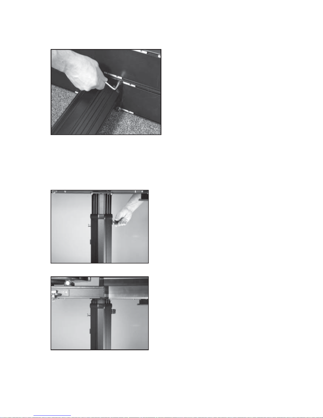
Floor Stand Leg Assembly
The stringing machine uses a four leg fl oor
stand design. The legs must be assembled
to the Lower Column before use. Remove
all parts from the shipping carton to confi rm
that contents match the parts list.
Align the holes in the Leg Flange with the
matching holes in the Lower Column. Secure the leg with one M8x30 fl at head screw
through the upper hole, and one M8x35
socket head cap screw through the bottom
hole. Repeat this procedure for the three
remaining legs.
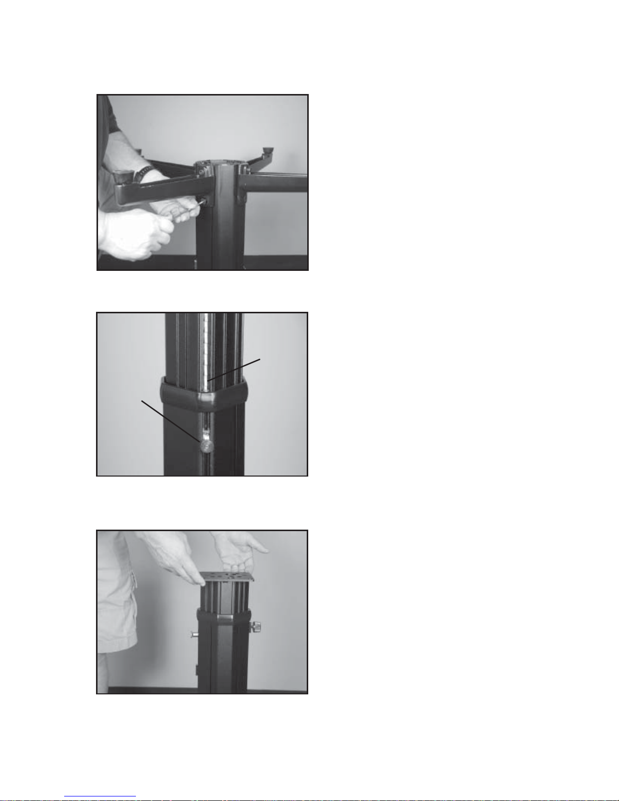
Floor Stand Assembly
The fl oor stand features a ratcheting
Self-Locking system that incorporates a
Gear
Track
Spring
Pin
in the shallow slot, the Spring Pin will be retacted and not engage the Gear Track.
Spring Pin on the lower column to engage
a gear track in the upper column. To set
the Spring Pin to engage or disengage
the Gear Track, pull the Spring Pin Knob
out out from the housing and rotate it 90
degrees to position the Knob Key into
the deep or shallow slot of the Spring Pin
Housing. When the Knob Key is positioned
in the deep slot, the Spring Pin will be in
the Self-Locking position and will engage
the Gear Track. When the Knob Key is set
Spring Pin
Engaged
Helpful Tip: When setting the height, it is best to start from the lowest position and gradu-
ally raise the height until the Slef-Locking Spring Pin is engaged in the Gear Track at the
desired height.
Lock Knob
Loosened
Floor Stand Assembly
With the Spring Pin engaged and the Knob
Key positioned in the deep slot, loosen that
Lock Knob and lift the upper column. As the
upper column is lifted out of the lower column,
the Spring Pin will ratchet as it engages and
disengages the teeth of the gear track.
To lower the upper column, loosen the Lock
Knob and while holding and supporting the
upper column, pull out the Spring Pin, set the
Knob Key into the shallow slot and lower the
upper column.
5
ASSEMBLY INSTRUCTIONS
Attaching the Floor Stand to the
Machine Base
Refer to the instruction sheet provided with
the fl oor stand for detailed instructions on
which holes of the fl ange plate to use and
align with the threaded inserts located in the
slots on the underside of the machine base.
With the fl oor stand assembled and the up-
per column locked into position at the lowest
height, orient the fl oor stand so that the string
reel holder will be positioned on the left side
of the machine base and bolt the fl oor stand
to the underside of the machine base. The
fl oor stand can be assmbled to the machine base with the machine base laying on the fl oor,
or by setting the machine base on top of the fl oor stand with the help of an assistant to align
and balance the machine base on the fl ange plate while installing and tightening the bolts
from the underside.
Caution: To prevent damaging the threads of the inserts in the machine base, do not overtighten the bolts.
Raising the Height of the Machine
To raise the height of the machine, the Knob Key
of the Spring Pin should be positioned in the deep
slot of the housing to ensure that the Spring Pin
is in the Self-Locking position and engaged with
the Gear Track. Loosen the Lock Knob and with
the help of an assistant, lift the machine base until
the desired height is reached. When the desired
height is reached, tighten the Lock Knob.
Lowering the Height of the Machine
T o lower the machine, you will need the help of an
assistant. With one person holding up and supporting the base of the machine, loosen the Lock
Knob, pull out the Spring Pin and set the Knob
Key into the shallow slot of the spring pin housing.
Carefully lower the machine base until it comes
to rest on the top of the Lower Column. Pull out
the Spring Pin and position the Knob Key into the
deep slot of spring Pin housing. Lift the machine
base until the Spring Pin engages the fi rst tooth
of the Gear Track and tighten the Lock Knob, or
continue raising the machine until the desired height is reached and then tighten the Lock Knob.
CAUTION: To prevent damage to the string gripper, never lift or
move the machine by the string gripper.
6
ASSEMBLY INSTRUCTIONS
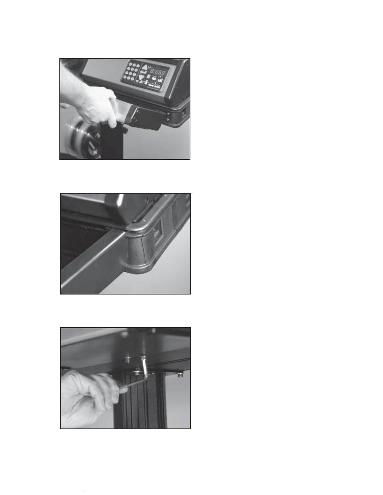
Tool Tray Installation
The T ool Tray will be attached to the aluminum
extruded machine base on the right hand
side below the tensioner. To install the tool
tray orient the tray at an angle and carefully
insert the keyed tabs into the horizontal slot
along the top edge of the base.
With the keyed tabs located within the slot in
the machine base slide the tray to the right
edge of the machine and next to the corner
cap of the base. Rotate the tray down until it
is fl ush against the machine base.
holes line up and tighten the set screw to lock the threaded insert in place.
Secure the bracket on the rear of the Tool
Tray to the machine base with two hex head
bolts. Align the two holes in the bracket with
the threaded holes in the threaded insert
located in the machine base. Tighten the
bolts with a 6mm hex wrench.
Caution: To prevent damaging the threads
of the inserts in the machine base, do not
overtighten the bolts.
Note: If the holes in the bracke do not line up
with the holes in the threaded insert, loosen
the set screw in the threaded insert and slide
the threaded insert to the left or right until the
7
ASSEMBLY INSTRUCTIONS
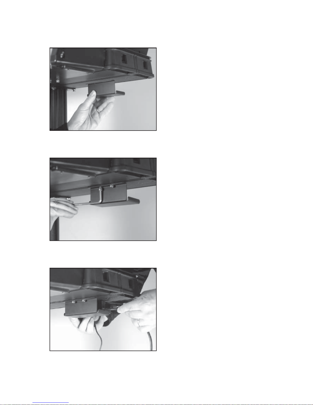
AC Power Adapter Storage Shelf
The AC Power Adapter Storage Shelf provides a means to secure and protect the
power adapter by storing it safely under the
machine base. This will reduce a potential
tripping hazard as well as eliminate potential
damage to the AC Power Supply if laying
on the fl oor.
AC Power Adapter Storage Shelf
Mount the Storage Shelf to the threaded
insert in the machine base near the rear right
corner. Align the holes in the storage shelf
bracket with the holes in the threaded insert.
Use a 6 mm hex wrench to tighten the two
hex head cap bolts.
Caution: To prevent damaging the threads
of the inserts in the machine base, do not
overtighten the bolts.
Note: If the holes in the bracket do not line up
with the holes in the threaded insert, loosen
the set screw in the threaded insert and slide
the threaded insert to the left or right until the holes line up and tighten the set screw to lock
the threaded insert in place.
AC Power Adapter Storage Shelf
Place the AC Power Adapter onto the storage
shelf. The excess cable can be coiled up
and placed between the top of the AC Power
Adapter and the machine base.
8
ASSEMBLY INSTRUCTIONS
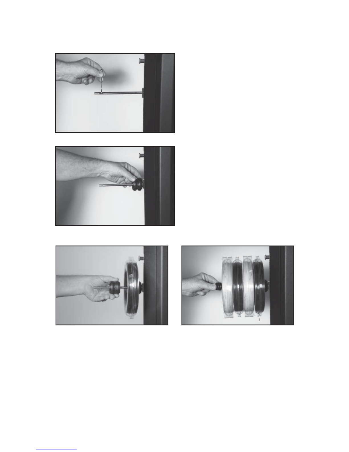
String Reel Installation
The String Reel Holder pin is an 8 mm rod
with threads on both ends and fl at surfaces
machined on one end. Thread the end of the
rod without the fl at surfaces into the threaded
boss on the right side of the Lower Column.
Using the M6 open end wrench positioned on
the fl at surfaces, securely tighten the rodto
the Lower Column.
The String Reel Holder can hold up to 4 reels
of string (depending on the size of the string
reel). Before placing the fi rst reel on the rod,
slide two spacers over the pin and slide them
to the boss on the Lower Column.
After the fi rst reel is placed onto the rod, place two spacers between each reel to provide
enough space between reels to allow them to turn freely without rubbing against one another.
(To provide a smooth feed to the String Length Meter , place the reels on the rod so the string
spools off the reel from the underside of the reel).
After the last reel is installed, place two washers on the rod and attach the threaded knob to
the end of the rod.
Note: The String Reel Holder can be repositioned anywhere you wish on the lower column
by loosening the set screws in the threaded boss and repositioning the threaded boss in the
lower column.
9
 Loading...