

Page 1
7000 Es
STRINGING MACHINE
OWNER'S MANUAL
Issue 3 - March 29, 1999Issue 3 - March 29, 1999
Issue 3 - March 29, 1999
Issue 3 - March 29, 1999Issue 3 - March 29, 1999
Copyright 1999 GAMMA Sports - All Rights Reserved
Page 2

7000ES
OWNER'S MANUAL
TABLE OF CONTENTS
INSIDE FRONT COVER ..................................................................... WARRANTY
PAGE 1 ................................................................................................. FEATURES
PAGE 2......................................................................... PARTS AND UNPACKING
PAGE 3..................................................................... ASSEMBLY INSTRUCTIONS
PAGE 8........................................................................... MOUNTING THE FRAME
PAGE 10 .........................................................................STRINGING THE FRAME
PAGE 13 .................................................................................. PATHFINDER AWL
PAGE 14 .................................................... MAINTENANCE AND ADJUSTMENTS
PAGE 15 .............................................................................. TROUBLESHOOTING
PAGE 15 ............................................................................ CARE AND CLEANING
PAGE 16 .............................................................. PART NUMBERS AND LISTING
LIMITED WARRANTY
GAMMA SPORTS ("GAMMA") warrants to the original purchaser that the GAMMA stringing machine ("EQUIPMENT")
purchased is free from defects in materials and workmanship for a period of five (5) years from the date of original purchase
for mechanical parts (excluding electronic parts and string clamps), and for a period of one (1) year from the date of purchase
for electronic parts and string clamps. Should any defects develop under normal use within the specified time periods, GAMMA
will at its option, repair or replace the defective EQUIPMENT provided it is returned to GAMMA prepaid at the purchaser's
expense. This warranty does not apply to any damage or defect caused by negligence, abuse, misuse, unauthorized
alteration, shipping, handling, or part wear and tear as a result of normal use.
GAMMA's obligation under this warranty is limited to repair or replacement of defective EQUIPMENT, and no one is authorized
to promise any other liability. GAMMA shall in no event be liable for any incidental or consequential damages.
To return defective EQUIPMENT, a return authorization (RA#) must be obtained from a GAMMA customer service
representative by calling 1-800-333-0337. The RA# must be marked on the outside of the shipping carton being returned. All
returns must be shipped prepaid by the customer to GAMMA. Please retain the original shipping carton and packing materials
for any future shipments.
Page 3
7000ES
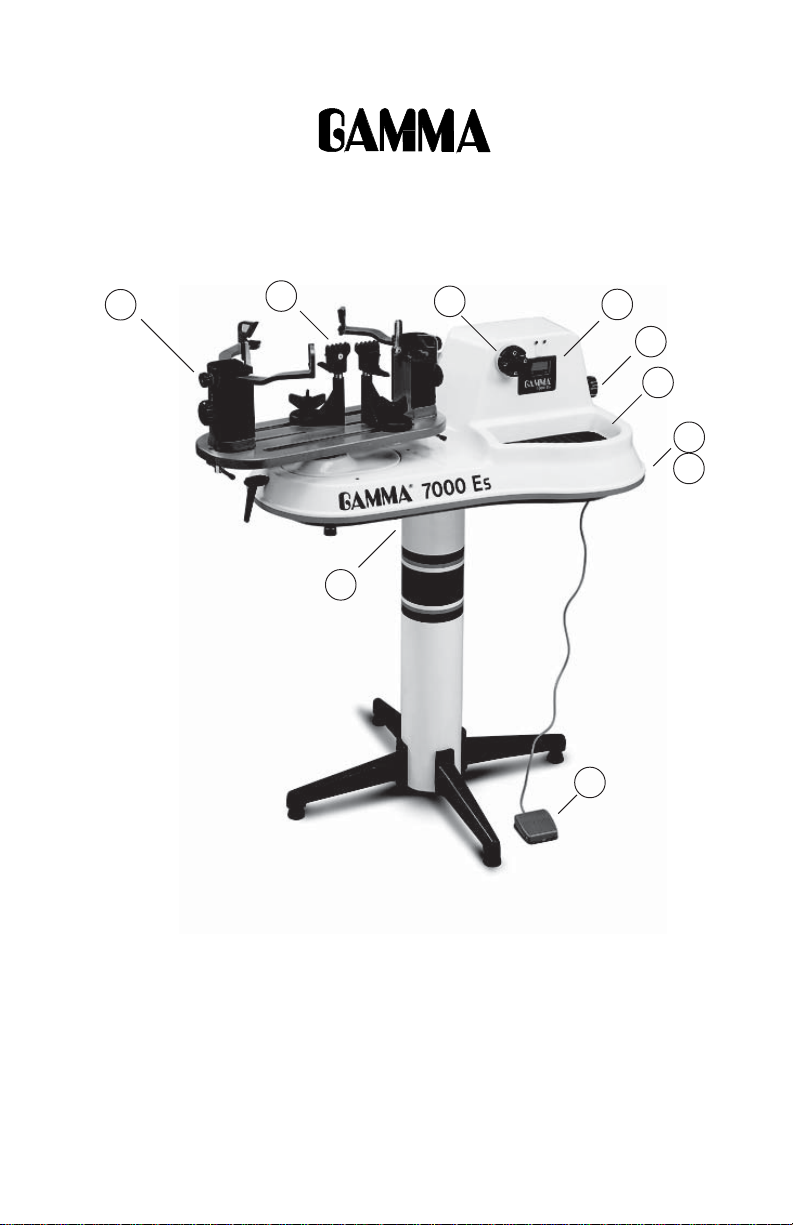
Key Product Features
5
6
9
1
2
3
8
4
10
7
1. Electric Constant Pull String Tensioner w/ Diamond Coated String Gripper
2. Large LED Readout
3. 10-89 lbs Tension Range in 0.5 lb increments
4. Two Tensioning Speeds (slow for aramid and metallic & fast for synthetic and gut)
5. 6 Point “Suspension” Mounting System (10 point support)
6. Dual Action, Swivel, Composite Coated Steel String Clamps w/ Diamond Coating
7. Convenient Foot Actuated Tensioner Switch
8. Full Fiberglass Cover w/ Integrated 70 sq in Tool Tray
9. Height Adjustable from 39” to 46” (can also be used on table top)
10. 110 V / 220 V Compatible
1
Page 4

7000ES
Parts and Unpacking
Instructions for Unpacking and Preparing for Assembly
The 7000 Es is shipped in two cartons, a large carton for the stringing machine and
accessories and a smaller carton for the post and base. Please save the cartons and
packing materials for possible shipments in the future. Gamma Sports can not be responsible for machines which are not shipped in there original, undamaged packaging. The only
tools you will need to assemble the 7000 Es is a screw driver. The balance of tools needed
for assembly are provided with the machine. Due to the weight of the tensioner unit, you
may need the assistance of someone to help lift the tensioner unit out of the carton.
Once the cartons are opened, remove all inner cartons and check to be sure that all parts
are accounted for. DO NOT REMOVE THE FOAM PACKING MATERIALS AROUND THE
BASE OF THE TENSIONER UNIT AT THIS TIME. THIS PACKING MATERIAL SHOULD
REMAIN IN PLACE TO PROTECT THE TENSIONER WHILE REMOVING IT FROM THE
INNER CARTON.
Small Post Carton Contains :
(1) Lower Post
(2) Upper Post with Flange
(4) Legs
(1) Winged Locking Knob Screw
(4) M8 x 25 Flat Head Screws
(4) M8 x 30 Cap Screws
Large master carton is a double carton with an inner carton containing :
(1) Tensioner Assembly with Turntable Installed (bolted to inner carton)
(1) Power Cord
(2) Suspension Mounting Stands w/ Side and Slide Support Fitted w/ Plastic Adapters
(2) Fixed String Clamps w/ Bases, Slide Bushings, and Wing Nut Screws
(2) Mounting Stand Locking Levers w/ Washers
(2) Badminton Frame Support Slides w/ Plastic Adapters
(1) Package of Spare plastic adapters for mounting system (contains 12 pcs)
(4) Rubber Feetw/ Screws
(1) Foot Pedal Tensioner Switch
(1) Tool Kit (contains side cutter, bent nose pliers, needle nose pliers)
(1) Straight Stringers Awl
(1) Pathfinder Specialty Awl
(2) Composite Badminton Floating Clamps
(1) 6 mm “T” Handle Hex Wrench
(1) 5 mm “T” Handle Hex Wrench
(1) 4 mm “T” Handle Hex Wrench
(1) 2 mm “L” shaped Hex Wrench
(1) 2.5 mm “L” shaped Hex Wrench
(1) 3 mm “L” shaped Hex Wrench
2
Page 5
ASSEMBLY INSTRUCTIONS
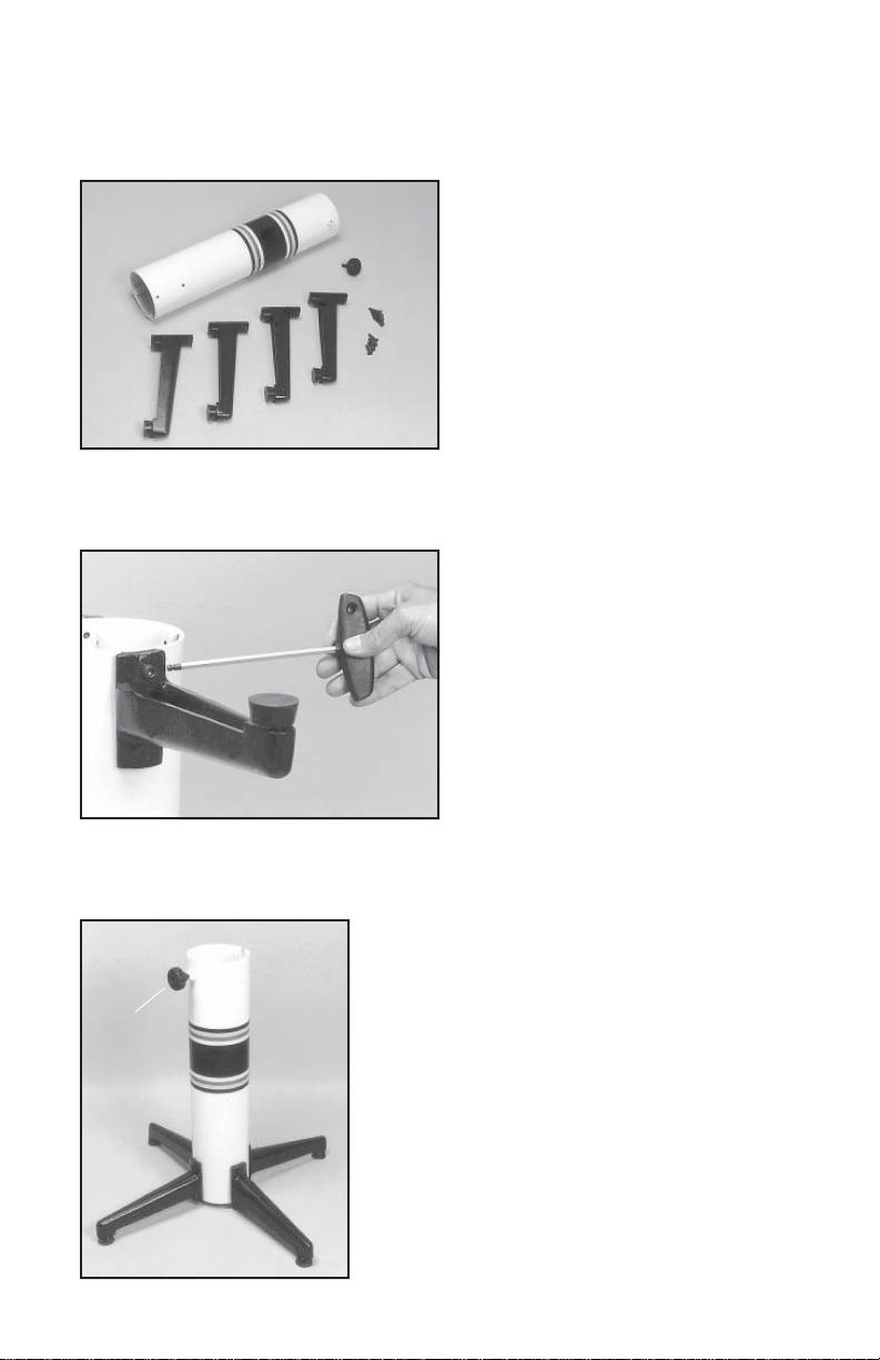
Base Leg Assembly
The GAMMA 7000ES stringing machine uses
a four leg base design. The legs must be
assembled to the support post before use.
Remove the lower column support, the upper column support, four (4) legs, four (4)
socket head cap screws and four (4) flat head
cap screws from the small shipping carton.
Base Leg Assembly (Cont.)
Align the holes in the leg flange with the
matching holes in the lower column support
post. Secure the leg with one FLAT HEAD
cap screw through the upper hole, and one
SOCKET HEAD cap screw through the bottom hole. Repeat this procedure for the three
remaining legs.
Base Leg Assembly (Cont.)
To complete the base stand, screw the height adjustment locking knob (“A”) into the side of the support
column. The locking knob should not protrude beyond
the inside of the support column at this time.“A”
3
Page 6
ASSEMBLY INSTRUCTIONS
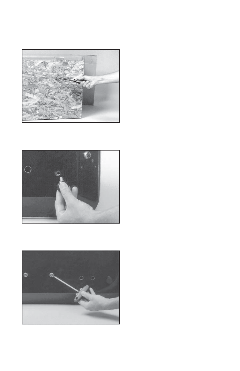
Unpacking the Tensioner
The tensioner assembly is packed and secured to the inner carton by two sheets of
wood and four (4) bolts. With the foam packing still in place around the base of the
tensioner assembly, remove the inner carton
and lay it on its side on the floor. Remove the
four (4) shipping bolts from the underside of
the carton with a screw driver. Upright the
carton on the floor and remove the tensioner
assembly. Retain the bolts, wood and cartons for future shipment.
Foot Installation
CAUTION : To maintain the alignment
between the fiberglass covers and the
frame, it is very important that the feet be
installed before removing the four center
screws that attach the tensioner assembly to the upper post flange.
To install the feet, tilt the tensioner back on its
side and screw the four feet into the holes at
the corners of the base.
Stand Upper Post Installation
After installing the four corner feet, remove
the four (4) button head cap screws and flat
washers from the base of the tensioner.
4
Page 7

ASSEMBLY INSTRUCTIONS
Stand Upper Post Installation (cont.)
With the height adjustment cap screw on the
upper post facing the right side of the
tensioner, align the four (4) holes in the upper
post flange with the holes in the tensioner
base. Secure the flange to the base with the
four cap screws and flat washers.
Height Adjustment
The turntable height of the Gamma 7000ES
is adjustable from 39” to 46”. To change the
height, remove the socket head cap screw
from its current position and place it in the
appropriate hole to set the desired height of
the machine.
Installing the Turntable
Insert the center post of the turntable into the
bearings of the stringing machine base. Make
sure that the turntable brake is not engaged
before installing the turntable.
5
Page 8

ASSEMBLY INSTRUCTIONS
Installing the Racquet Mounting System
Align the threaded hole in the bottom of the
frame support post with the slot in the turntable. Screw the lever lock bolt with washer
into the outermost hole located in the bottom
of the support post and tighten gently.Position
the washer with the rounded edge toward the
turntable.
Repeat procedure for the support post on the
opposite side of the turntable.
There are two holes located in the bottom of
the support post. The inner hole is for use
tional separation space between the mounting arms. The outer holes should be used whenever
possible provide maximum support for securing the support post to the turntable.
with super oversize racquets to provide addi-
Installing the Fixed Clamps
To install the clamps, remove the winged
lock knob to separate the knob from the lower
guide bushing. Be careful not to lose the
radial thrust bearing components located in
the center recess of the knob.
Align the clamp base with the clamp slot of
the turntable base. Insert the clamp guide
bushing into the clamp from the bottom of the
turntable making sure to engage the guide
with the clamp slot.
Fixed Clamp Installation
Place the load bushing into the top of the
clamp base mating it to the lower guide
bushing. After checking that the thrust bearing is positioned correctly in the base of the
winged lock knob, screw the knob into the
base bushing until fully seated.
The post of the string clamp head and tube of
the string clamp base are treated with grease
to provide protection against corrosion during shipping. Remove any excessive grease
with a clean cloth prior to use. The post and
alcohol. After this type of thorough cleaning, the post and tube should be treated with a light
coating of machine oil to protect the surfaces against corrosion and to ensure smooth operation.
tube may also be cleaned with isopropyl
6
Page 9

Connections & Controls
Refer to Figures 1 and 2 for power connection and control information.
Before connecting to the power supply, check the voltage supply switch setting
located on the side panel as shown in Figure 2. To change from 110 volts service to
220 volt service simply slide the switch fully to the right or to the left until “110V” or
“220V” appears on the switch plate.
To install the power cord, simply insert the female end of the power cord into the Power
Cord Socket located on the side panel and plug the male end into a grounded power outlet.
When using extension cords, use grounded heavy duty extension cords rated for 15 AMP
service. To connect the foot pedal switch, insert the 2 pin mail connector located at the end
of the foot pedal switch cord, into the two pin receptacle located in the side panel. Tighten
the connector with the sleeve nut located on the foot pedal switch connector.
“A”
“G”
“E” “F”
“B”
“L” “H”
Figure 1
Front Panel
“D”
“C”
Front Panel Features
“A” - Spilt Drum String Gripper
“B” - Tensioning Button Switch
“C” - Tension Adjustment Knob
“D” - L.E.D. Tension Display
“E” - Red LED
“F” - Green LED
“G” - L.E.D. Display Cover Plate
“H” - High Tension Calibration Port
“L” - Low Tension Calibration Port
“A”
Side Panel Features
“A” - Lighted On-Off Power Switch
“B” - Power Cord Socket
“C” - Sliding Fuse Holder w/ Spare Fuse
“D” - Gripper Reversing Switch
“E” - 110V / 220V Switch
“F” - 2 Pin Foot Pedal Switch Socket
“G” -Tensioner Speed Switch
“C”“D” “E”
“B”
Figure 2
Side Panel
“F”“G”
7
Page 10

MOUNTING THE FRAME
Adjusting the Frame Support Posts
Place the racquet frame over the center
support slide and onto the frame support.
Loosen the lever lock bolt on one support
post. Slide the post outward until the center
support of the racquet support slide is positioned near the inside surface of the racquet
frame. Securely tighten the lever lock bolt.
Adjust the opposite post using the same
procedure.
Caution: To avoid racquet damage, the support slide should not contact the racquet prior
to fixing the support posts.
Shoulder Support Adjustment
The shoulder supports on the 7000Es are
adjustable to provide support to the racquet
frame. Loosen the knurled knob at the bottom
of the shoulder support and swivel the support so that the pads will contact the frame
squarely when the arms are closed against
the racquet. Should the shoulder supports
block string holes, adjust the position of the
racquet between the arms until the shoulder
supports contact the racquet between grommet holes.
Securing the Shoulder Supports
Secure the racquet frame with the shoulder
supports by rotating the large adjustment
knobs on the outside of the support post
assemblies clockwise. Adjust the supports
until firm contact is made between the shoulder supports and the frame.
The tear drop shaped holes torwards the
back of the shoulder supports are handy
for holding the loose end of the string
while pulling the string through the
racquet. Simply insert the loose end into
the tear drop shaped holes and slide the
string into the point of the hole.
8
Page 11

MOUNTING THE FRAME
Support Slide Adjustment
Once the frame support posts are secured,
lightly tighten the support slides by turning
the knobs on the outside of the slides clockwise. Adjust the slides in equal increments
until slight resistance is felt.
Apply a final adjustment to all racquet support points until the racquet is firmly secured
in the mounting system.
Should the frame supports lose contact with
the frame while stringing, they should be
adjusted, as needed, to maintain contact with
the frame.
Setting Tension
The 7000 ES stringing machine utilizes a
rotary adjusting knob along with a digital
L.E.D. display to indicate the set tension. To
set the tension, rotate the adjustment knob
clockwise to decrease the displayed tension, counter-clockwise to increase the displayed tension, until the desired tension is
displayed on the digital display.
Setting Tensioner Speed
To maintain consistency in stringing tension
for all types of strings, the 7000 Es can be
set to pull at a fast or slow tensioning speed.
When pulled at high speed, stiff Aramid fiber
and Metallic strings will generally string up
4-5 lbs tighter on the 7000Es than synthetic
or natural gut strings. Therefore, when string-
Slow
Pull
which results in more accurate and consistent tensioning when using the stiffer aramid or
metallic strings.
Fast
Pull
ing with Aramid (Kevlar, Technora) hybrid
strings or metallic strings, the tensioner
speed switch, located on the side panel,
should be set to the slow pull position.
This decreases the motor speed by one half
9
Page 12

STRINGING THE FRAME
Fixed Clamp Operation
The fixed clamps supplied with your GAMMA
7000Es are of a dual action design. The
string clamp and the clamp base operate
independently of one another.
To clamp a string, lift the clamp head and
place the string between the jaws. Depress
the clamp head lever to secure the string.
The clamping pressure applied to the string
should be adjusted to provide sufficient pressure to secure the string when subjected to
the desired pulling tension. The diamond
friction between the clamps and the string to allow for reduced clamping pressure while securing
and holding the string under tension.
may be required. Note: If the string slips in the string clamp while tensioning, adjust the
gap between the clamp jaws as per the instructions on page 14.
coated gripper plates provide for increased
Fixed Clamp Operation
Rotate the winged lock knob clockwise to
secure the clamp base to the turntable.
Reverse the clamping procedure to unlock
the string clamp.
The winged lock knob should be tightened
enough to prevent clamp base slippage on
the turntable, when the desired tension is
placed on the string. To go from the loose
position to the clamped position and back,
generally requires about 1/2 to 3/4 quarters
of a turn. Although when stringing at extremely high tensions, additional tightness
String Gripper Operation
To insert the string in the split drum string
gripper, wrap the free end of the string
clockwise around the gripper drum and position the string between the gripper jaws as
shown in the illustration.
The string must pass over the top half of the
gripper before being placed between the
diamond coated plates of the upper and
lower gripper jaws. Excessive slack in the
string should be removed before applying
tension. As the drum turns and applies tension to the string, the upper jaw is forced
down to clamp the string between the jaws.
10
Page 13

STRINGING THE FRAME
Clamping the First Main String
To begin stringing the main strings, insert the
two ends of the string through the two center
holes at the appropriate end of the frame and
continue through the center holes on the
opposite end of the racquet.
Secure one of the strings using a string
clamp and insert the free end into the string
gripper.
Tensioning the First Main String
With the string properly inserted in the string
gripper, and the tensioner speed selected,
press the Tension Switch once and the
string gripper will rotate and slowly apply
tension to the string. When the set tension
has been attained, the gripper will stop
rotating and red LED will go out and the the
green LED turn on. As the tensioned string
stretches, the gripper will rotate intermittently, to maintain the set tension.
To release the string after clamping, press
backwards to release the string. If the string gripper does not rotate back to release the string,
press and hold the Gripper Reversing Switch, located on the end panel. Note : For the Gripper
Returning Switch to function properly, the Tension Switch must be in the tension mode.
Should the Gripper Reversing Switch not seem to function, press the Tension Switch once
and press and hold the Gripper Reversing Switch once again.
the tension switch and the gripper will rotate
Tensioning the First Cross String
Weave the cross strings over and under the
main strings being careful to alternate the
weave direction of each consecutive cross
string so as to be opposite of the previously
installed cross string.
11
Page 14

STRINGING THE FRAME
Once the final cross string is tensioned and
clamped, tie off at the appropriate hole specified by the racquet manufacturer.
Remove the strung racquet by loosening the
shoulder supports and support slides in small
increments until the racquet is free from the
mounting system.
12
Page 15

P ATHFINDER AWL OPERATION
The Gamma 7000Es includes the new Pathfinder stringing awl which creates a pathway
between or around strings to make inserting
a string through tight gromets easier and
quicker.
Insert the awl through the grommet hole in
the same manner as for traditional awls. The
Pathfinder awl must be in the closed position
before insertion.
Once the awl is inserted, pull the handle of
the awl outward while holding the tip section
in place, leaving the outer sheath in the
grommet hole.
Insert the end of the string into the center of
the sheath.
While holding pressure on the string, slowly
pull the sheath out of the grommet hole to
leave the end of the string exposed.
13
Page 16

MAINTENANCE and ADJUSTMENTS
Tension Calibration Procedure
If you suspect that your 7000Es is not pulling the
High KGs
High LBs
from the L.E.D. display cover plate cover. Rotate screw (“L”) in small increments until the
displayed tension matches the tension indicated on the calibrator. Set the machine tension
to 80 lbs. and apply tension to the calibrator. If the measured tension is innacurate, rotate
screw (“H”) in small increments until the displayed tension matches the tension indicated on
the calibrator. Since adjustment of the “L” screw at 20 lbs can influence the tension at 80 lbs
and visa versa, repeat these steps until the set tension matchs the tension reading of the
calibrator at both 20 and 80 lbs. Replace the 2 caps in the L.E.D. display cover plate.
Please note that there will be a range of tension from the maximum tension at which the
tensioner stops pulling (high end of the range), to the minimum tension at which the tensioner
starts pulling again (low end of the range). This difference between the high and low end of
the range can vary from 2-4 lbs depending on the string used to calibrate the machine and
the speed of the tensioner. For consistency, we recommend that the tension setting of the
machine be calibrated as close as possible to the high end of the range, using the fast pulling
speed and a synthetic string, which is the method used at the factory. Using this method will
be the most consistent and will also insure that the racquet will not be over tensioned.
88.8
LBs KGs
Low KGs
Low LBs
Selection
Switch
correct tension, you should check the tension
with a Gamma Tension Calibrator which provides
a measurement of the actual pulling tension
being applied by the machine.
With the machine set for the fast pulling speed,
and the tension set at 20 lbs., place one end of a
calibrator equipped with synthetic string into a
string clamp. Place the opposite end into the
string gripper and apply tension. If the measured
tension is inaccurate, remove the 2 small caps
Adjusting the String Clamps
The clamps provided with your stringing
machine will need minor adjustments according to what string type, construction,
and gauge you are using.
To adjust the gap (clamping pressure) between the clamp jaws, insert the string
through the racquet as if you were beginning
Adjustment
Knob
direction. If the clamp leaves impressions or damages the string, it may be excessively tight
and should be adjusted by turning the hex screw counter clockwise to open the gap between
the jaws. The clamp jaws should be cleaned periodically to be free from dirt, oil, and any string
coating for them to grip properly.
Note: The string clamps supplied with your Gamma stringing machine can accomodate tight
string patterns such as badminton. Depending on the string pattern, the clamp may spread the
strings slightly which will not compromise the quality of the string job.
the main strings. Clamp the strings and pull
tension. If the string slips through the jaws of
the clamp, tighten the clamp by turning the
Adjustment Knob, located on the fixed clamp
jaw opposite of the handle, in the clockwise
14
Page 17

TROUBLESHOOTING TIPS
PROBLEM SOLUTION
String slips in clamps
• Adjust gap between jaws
• Clean clamp jaws
String slips in string gripper
String clamp slips on base • Clean base of clamp and top of
String clamp Lock knob is difficult to turn
String tension too tight or too loose
Electrical system does not function • Check power source
To check fuse, remove the power cord and pull the fuse holder straight out. Remove the
fuse from the clips and examine it. If it is burned out, replace it with the spare fuse and
replace the fuse holder in its socket. Supply power to the machine and check for proper
operation. If problems persist, contact Gamma Sports Customer Service at 1-800-3330337
• Clean gripper jaws
• Make sure string is wrapped over
upper gripper jaw before inserting
between gripper jaw plates
turntable
• Check for proper position of thrust
bearing in the base of the winged lock
knob
• Check tension using a tension
calibrator and adjust machine
calibration if necessary
• Check power cord connection
• Check fuse
• Call Gamma Sports customer service
CARE and CLEANING
With time and use, the clamping surfaces of your machine may become oily or dirty and result
in string or clamp slippage while stringing. Periodic cleaning of the following parts is
recommended.
String Clamps
Clean the inside gripping surfaces of the string clamp jaws by inserting a cloth or pipe cleaner
soaked with isopropyl alcohol between the jaws and rub back and forth. If the build-up is
excessive, dismantle the string clamp jaws to expose the gripping surfaces by removing the
adjustment screw. Using a small nylon brush, (such as a toothbrush), scrub the inside
surfaces until all debris is removed. Clean the jaws with isopropyl alcohol and re-assemble.
String Clamp Base
Clean the base of the clamps and the top of the turntable with isopropyl alcohol.
String Gripper
Clean inner gripping surfaces with isopropyl acohol soaked cloth or pipe cleaner.
15
Page 18

118A
7000ES
Parts Summary
36
32A
33A
37
123
124
125
126
22A
21B
21A
134
22A
130
114
121
133
122A
128
132
135
115
129
6B
106
136
13
58
52B
127
57A
57
131
55
54A
56
16
Page 19

7000ES
Parts Listing
Part # Description
6B Cap Screw - M8 x 30
13 Locking Lever
21A Frame Support Slide SM Tennis
21B Frame Support Slide SM Badminton
22A Support Adaptors Black
32A Upper Gripper Jaw Black
36 Gripper Jaw Spring
33A Lower Gripper Jaw Black
37 Gripper Cap Screw Set
52B Clamp Head Assembly Black
54A Short Clamp Base Black
55 Guide Bushing
56 Guide Bushing Nut
57 Load Bushing
57A Radial Thrust Bearing
58 Winged Knob
106 Wing Locking Knob Screw
114 Short Leg
115 Flat Head Cap Screw -M8 x 25
118A Turntable SM
121 Leveling Foot
123 Gripper Drum Back Plate
124 LED Cover
125 Tension Adjustment Knob
126 7000Es Tensioner Assembly
127 Flanged Upper Support Column
128 FRP Base Foot
129 Lower Support Column
130 Brake Lever
131 Foot Pedal Switch
132 Mounting Arm Adjustment Knob SM
133 Support Slide Adjustment Screw SM
134 Suspension Mounting Arms
135 Shoulder Support Adjustment Knob SM
136 Shoulder Support SM
17
 Loading...