

Page 1
6900 Els
STRINGING MACHINE
2 POINT SC MOUNTING
OWNER’S MANUAL
Issue 4B - February 2014
Page 2

6900 Els
OWNER’S MANUAL
WARRANTY ................................................................................................ PAGE 3
FEATURES.................................................................................................. PAGE 4
UNPACKING & ASSEMBLY INSTRUCTIONS ............................................PAGE 5
POWER CONNECTION & CONTROLS ................................................... PAGE 10
MOUNTING THE FRAME .........................................................................PAGE 12
STRINGING THE FRAME ......................................................................... PAGE 13
ADDITIONAL FEATURES .........................................................................PAGE 16
STRING LENGTH METER ....................................................................... PAGE 17
PATHFINDER AWL ....................................................................................PAGE 18
MAINTENANCE & ADJUSTMENTS ......................................................... PAGE 19
TROUBLESHOOTING TIPS ..................................................................... PAGE 21
PARTS LIST ............................................................................................. PAGE 22
PARTS DRAWING.....................................................................................PAGE 23
LIMITED WARRANTY
GAMMA Sports (GAMMA) warrants to the original purchaser that the 6900 Els stringing machine (“EQUIPMENT”) purchased is free from defects in materials and workmanship for a period of fi ve (5) years from the date of original purchase
for mechanical parts and for a period of one (1) year from the date of purchase for all electrical parts and string clamps.
Should any defects develop under normal use within the specifi ed time periods, GAMMA will at its option, repair or replace
the defective EQUIPMENT provided it is returned to GAMMA prepaid at the purchaser’s expense. This warranty does not
apply to any damage or defect caused by negligence, abuse, misuse, unauthorized alteration, shipping, handling, or part
wear and tear as a result of normal use.
Routine maintenance, adjustment, and cleaning required to ensure proper operation are the responsibility of the purchaser and
are not covered under the terms of this warranty. These include, but are not limited to: String Clamp adjustment, as described
on page 20, Quick Action Clamp Base adjustment, as described on page 20 and the cleaning procedures listed on page 21.
GAMMA’s obligation under this warranty is limited to repair or replacement of defective EQUIPMENT, and no one is authorized
to promise any other liability. GAMMA shall in no event be liable for any incidental or consequential damages.
To return defective EQUIPMENT, a return authorization (RA#) must be obtained from a GAMMA customer service representative. The RA# must be marked on the outside of the shipping carton being returned. All returns must be shipped prepaid by
the customer to GAMMA. Please retain the original shipping carton and packing materials for any future shipments. GAMMA
will not be responsible for machines which are not sent in the original undamaged packaging.
A GAMMA Care Service Plan is also available through GAMMA customer service, call 800.333.0337 for details.
TABLE OF CONTENTS
3
Page 3
FEATURES
MACHINE FEATURES
Electronic Constant Pull Tensioner with 11.0 to 90.0 lbs Tension
Range
Digital Tension Setting with LED Display
Professional Self-Centering Two Point Racquet Mounting Sys-
tem- Accommodates All Racquets
Parallel Jaw Rotating Gripper with Diamond Dust Coated Grip-
ping Surfaces
Professional “Quick Action” Dual Action, Rotating, Metal Fixed
String Clamps with Diamond Dust Coating
Fiberglass Cover with Convenient Padded Tool Tray enclosing
a High Strength Aluminum Frame
Convenient Foot Actuated Tensioner Switch
4
Page 4

6900 Els
Unpacking Instructions & Contents
Instructions for Unpacking and Preparing for Assembly
The stringing machine is shipped in three cartons, a large master carton for the stringing
machine base with tensioner module and accessories, a medium carton for the turntable
and mounting system and a smaller carton for the fl oor stand post and base legs. Please
save the cartons and packing materials for possible shipments in the future. Gamma
Sports cannot be responsible for machines that are not returned, shipped in their original,
undamaged packaging. The tools you will need to assemble the machine are provided
with the machine. Due to the weight of the tensioner unit, you may need the assistance of
someone to help lift the tensioner unit out of the carton.
Once the cartons are opened, remove all inner cartons and check to be sure that all parts
are present and accounted for.
Contents of Floor Stand Carton (MMU2-16)
(1) Lower Column
(1) Upper Column with Flange Plate
(4) Legs
(1) Locking Knob Screw
(4) M8 x 25 Flat Head Screws
(4) M8 x 30 Cap Screws
(8) M8 Nuts
(1) 12mm Wrench
(4) M6 x 20 Cap Screws
(1) M8 x 25 Cap Screws for Height Adjustment
(1) String Reel Holder (M8 Threaded Pin), (1) Knob, (10) Spacers, & (2) M8 Washers
Contents of Mounting System Carton (MMU2-67)
(1) Turntable Assembly w/String Clamp Bases and Mounting Stands
(2) String Clamps
(1) 17mm Socket
Contents of Large Master Carton (MMU2-12)
(1) Stringing Machine Base w/ Tensioner Module
(1) Power Cord
(1) Foot Pedal Tensioner Switch
(1) Tool Kit (contains side cutter, bent nose pliers, needle nose pliers, starting clamp)
(1) Straight Stringers Awl & (1) Pathfi nder Specialty Awl
(1) Tools for assembly and maintenance
5
Page 5
ASSEMBLY INSTRUCTIONS
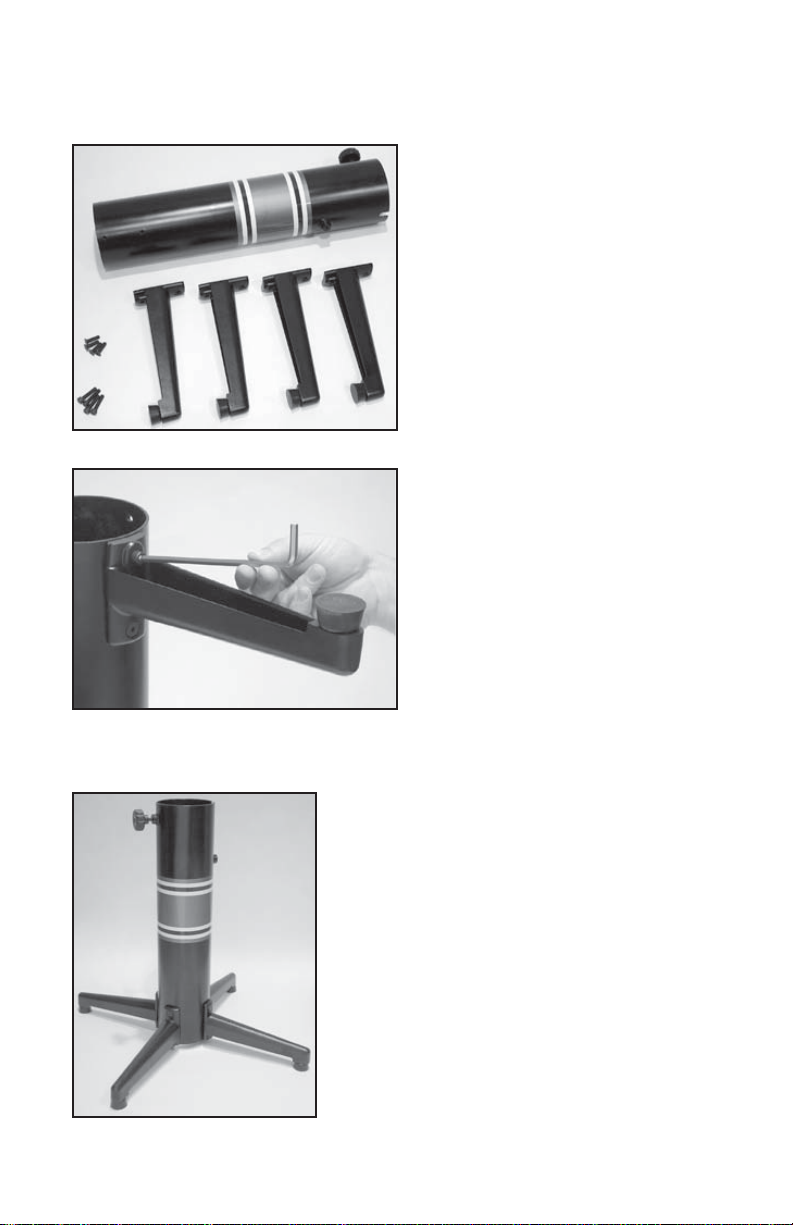
Floor Stand Assembly
The stringing machine uses a four leg
fl oor stand design. The legs must be assembled to the lower column before use.
Remove all parts from the shipping carton
to confi rm that contents match the list of
parts on Page 5.
Floor Stand Leg Assembly
Align the holes in the leg fl ange with
the matching holes in the lower column.
Secure the leg with one M8 FLAT HEAD
screw through the upper hole, and one
M8 SOCKET HEAD cap screw through
the bottom hole. Install one 8mm nut on
each screw. Repeat this procedure for the
three remaining legs.
Floor Stand Assembly (Continued.)
To complete the fl oor stand, screw the height adjustment locking knob (“A”) into the side of the lower
column. The locking knob should not protrude beyond
the inside surface of the lower column at this time.
6
Page 6
ASSEMBLY INSTRUCTIONS
Height Adjustment
The height of the machine is adjustable
from 39” to 46” in approximate 1” increments. To change the height, remove the
socket head cap screw from its current position and place it in the appropriate hole
to set the desired height of the machine.
Be sure to thread the screw completely
into the upper column so the head of the
cap screw rests in the notch of the lower
column that is parallel to the string reel
holder.
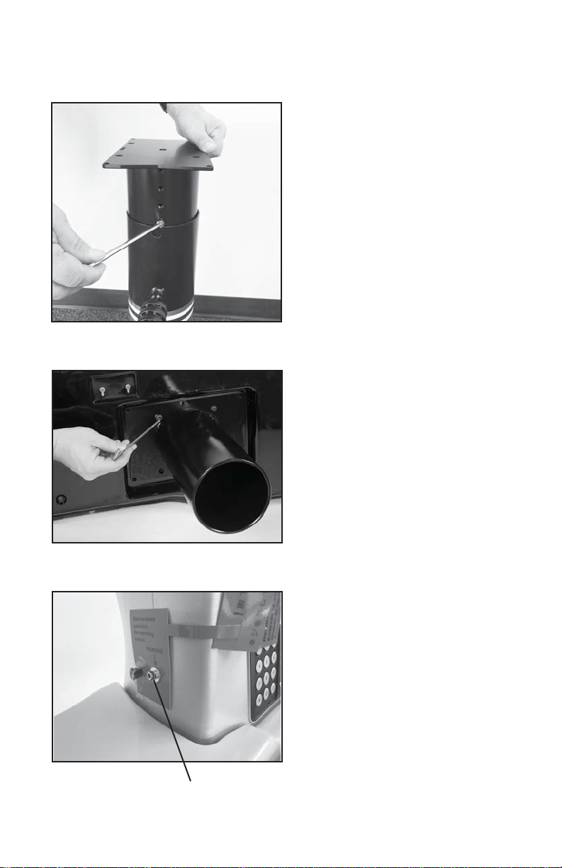
Stand Upper Post Installation
With the height adjustment cap screw on
the upper column facing the string reel
holder, align the four holes in the upper
column fl ange with the threaded holes in
the machine base. Lift the machine base
and insert the upper post into the lower
column until the head of the cap screw
rests in the notch of the lower column and
tighten the locking knob.
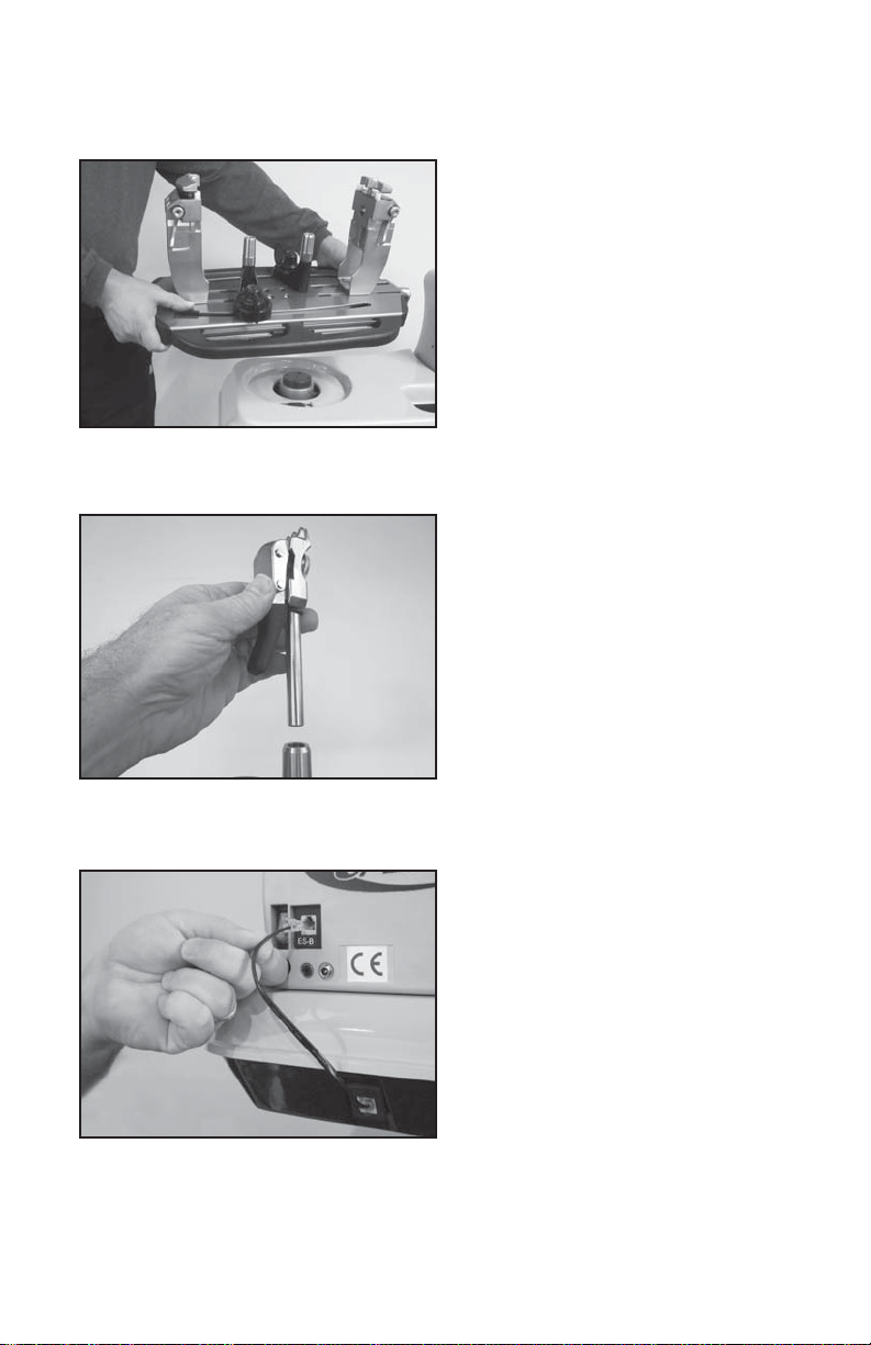
Remove this Screw
Transportation Screw
The machine has been shipped with a motor
and load cell protection screw. Remove the
screw before using the machine. Retain the
screw for future shipment. Install the included
rubber grommet into the hole.
7
Page 7
ASSEMBLY INSTRUCTIONS
Turntable and Mounting System
Installation
To install the turntable position the turntable
over the turntable pin and align the bolts,
located in the poly bag, with the holes in
the fl ange. Secure them with the included
allen wrench.
String Clamp Installation
The post of the string clamp and tube of the
string clamp base are treated with grease to
provide protection against corrosion during
shipping. Remove any excessive grease with
a clean cloth prior to use. The post and tube
may also be cleaned with isopropyl alcohol.
After this type of thorough cleaning, the post
and tube should be treated with a light coating
of machine oil to protect the surfaces against
corrosion and to ensure smooth operation.
String Length Meter Wire Installation
Connect the black string length meter wire
to the receptacle in the black FRP base and
to the back of the tensioner.
8
Page 8
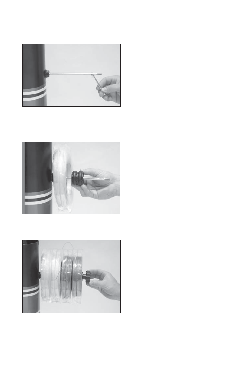
STRING REEL HOLDER INSTALLATION
The string reel holder is an 8 mm rod with
threads on both ends, and fl at surfaces
machined on one end. Thread the end of
the rod without the fl at surfaces into the
threaded boss on the side of the lower
column. Using the M6 open end wrench
positioned on the fl at surfaces, securely
tighten the rod to the lower column.
The string reel holder can hold up to 5
reels of string (depending on the size of
the string reel). Before placing the fi rst reel
on the rod, slide two M8 washers over the
pin and slide them to the boss on the lower
column. After the fi rst reel is placed onto
the rod, place two spacers between each
reel to provide enough space between
reels and allow them to turn freely without
rubbing against one another. (To provide
a smooth feed to the String Length Meter,
place the reels on the rod so the string
spools off the reel from the underside of
the reel).
After the last reel is installed, place the
remaining spacer(s) on the rod and attach
the threaded knob to the end of the rod.
9
Page 9
POWER CONNECTION & CONTROLS
A
B
C
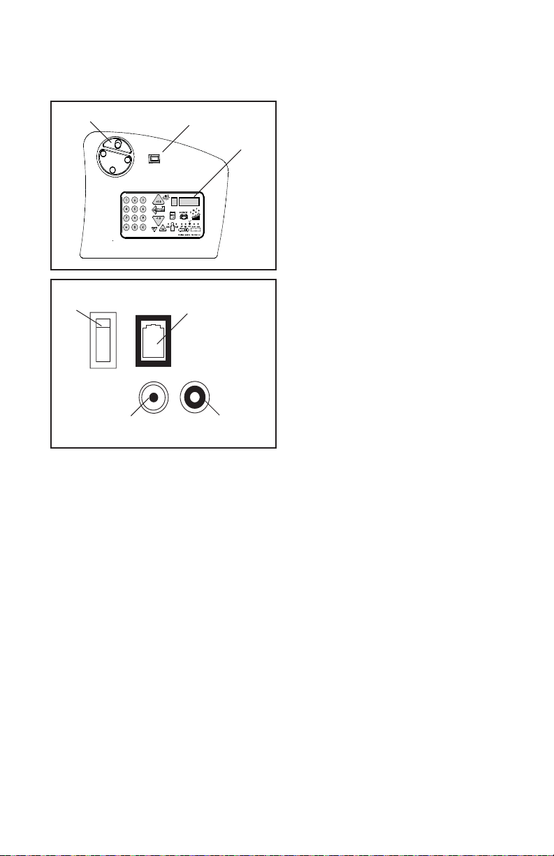
Front Panel Features
A - String Gripper
B - Tension Switch
C - Control Panel
Back Panel Features
A
B
D
C
A - Lighted Power Switch
B - Foot Pedal Switch Receptacle
C - A/C Power Cord Socket
D - String Length Meter Socket
Instructions for Power Connection and Controls
CAUTION ! Before connecting to the power supply, check the voltage source that the
machine is being connected to. The acceptable range of input voltages for this machine is between 100 V and 240 V @ 50 to 60 Hz. If you have any questions regarding
the input voltage supply for your area, please ask your electric utility company.
To install the power cord, insert the female end of the power cord into the AC Adapter and
then insert the female end of the cord from the AC Adapter into the A/C Power Cord Socket
“C” located on the back panel of the tensioner. Plug the male end of the power cord into a
grounded power outlet. When using extension cords, use grounded heavy duty extension
cords rated for 15 AMP service.
To connect the foot pedal switch, insert the male pin at the end of the foot pedal switch cord
into the Foot Pedal Switch Receptacle “B” located on the back panel of the tensioner.
Switch on the machine by pressing the Lighted On-Off Power Switch on the back panel. At
start-up, the LED will display a countdown from “9.0” to “0.0” while the machine performs a
self diagnostics check at start-up.
WARNING! FOR INDOOR USE ONLY.
NEVER OPEN UNIT WITH POWER CONNECTED.
CHILDREN SHOULD NEVER BE PERMITTED TO OPER-
ATE THIS MACHINE WITHOUT ADULT SUPERVISION.
10
Page 10

CONTROL PANEL FUNCTIONS
AND FEATURES
Tension Index Buttons - Changes
tension setting in +/- 1.0 or +/- 0.1 Lb or
Kg increments. Holding the button down
will scroll the tension setting values up
or down. Tension settings entered with
the tension index buttons are placed into
temporary memory setting “0”.
Clear Button - Clears display to enter
a new tension or to reset String Length
Meter measurement.
Test Button & Racquet Strung -
Press once for approximate number of
racquets strung. Press again to return.
Press and hold for 5 seconds and the
machine does an internal diagnostic
check, such as the one performed at
start-up.
Single Digit (1-9)
Memory LED Display
Memory Button - Indexes from 9 preset
tension settings that can be stored in
memory. Settings are retained even if
machine is turned off. Each press of
the button indexes to the next memory
setting. Memory settings 1-9 must be
entered using the keypad followed by
pressing the “ENT” button.
Enter Button - Saves displayed tension
for Memory setting - when tension is entered using the keypad display fl ashes
until this button is pressed to save the
setting. Also Clears display for String
Length Meter measurements.
Knot Function - Increases pulling tension by 10% over the setting value (max
90 lbs / 40.8 kgs) for one pull. During the
pull the LED stays lit to indicate the Knot
function is enabled.
Three Digit (XX.X)
Tension Setting Display or String Length
LED Display
Lbs/Kgs Button - Changes tension
display from Lbs to Kgs. Each press
of the button toggles back and forth
between Lbs and Kgs.
Pre-Stretch Function - Pulls string 10%
or 20% over the tension setting (up to 90
lbs / 40.8 kgs), releases the string, and
repulls to the tension setting. Each press
of the button toggles between 10%, 20%
or no pre-stretch.
Speed Button - Changes pulling speed
of winder from Fast (default) to Medium
to Slow. Slow speed is recommended
for low stretch strings, such as Kevlar.
Each press of the button toggles between Fast, Medium and Slow speeds.
String Length Meter Button- Enables
string length meter function. Each press
of the button toggles between Meters
and Feet. To switch back to tensioning
function, press the “Lbs/Kgs” button.
11
Page 11

MOUNTING THE FRAME
Adjusting the Inner Racquet Supports
The white racquet supports are adjustable to accommodate
all racquets and provide maximum support to the racquet
frame. Screw the pads up or down so they contact the frame
at a maximum height without blocking the grommet holes.
Mounting Stand Adjustment
When mounting a racquet, adjust the
Mounting Stands so that the white Racquet
Supports on top of the Mounting Stands fi t
inside the hoop of the racquet. Lower the
racquet over the Racquet Supports and adjust the Mounting Stands until the supports
just make contact with the inside surface of
the racquet at the head and throat. There is
an arrow on the face of each knob indicating the turning direction that will “Tighten”
the mounting points by moving the 2pt
Racquet Supports closer to the inside surface of the racquet at the head and throat. Turning
the knobs in the opposite direction will move the Mounting Stands closer together and will
allow the Racquet Supports to move away from the racquet frame.
Mounting Stands further apart to bring the
Racquet Hold Down Clamp Operation
With the lever in the up position, insert the racquet hold
down clamp pin into the hole in the center of the mounting stand. Lower the hold down clamp until it just makes
contact with the surface of the racquet. Using slight palm
pressure on the hold down clamp depress the racquet
hold down lever completely to secure the racquet frame
to the stand.
12
Page 12

MOUNTING THE FRAME
Special Throat Mounting
For racquets with a bridge that is thinner than
the rest of the frame or are tapered from head
to throat you may need to mount the racquet
with the shafts of the racquets supported by
the white support pads as pictured.
BRIDGE
STRINGING THE FRAME
String Clamp Operation
The string clamps are a dual action design
where the string clamp and clamp base operate independently of one another.
To clamp a string, lift the string clamp, place
the string between the jaws and depress
the string clamp lever to secure the string.
The clamping pressure applied to the string
should be adjusted to provide suffi cient pressure to secure the string when subjected to
the desired pulling tension. The diamond
coated gripper plates provide for increased
to allow for reduced clamping pressure while securing and holding the string under tension.
Note that excessive pressure can damage both the strings and String Clamp.
friction between the clamps and the string
Clamp Base Operation
To lock the string clamp base to the turntable,
rotate the clamp base locking lever clockwise.
To release the string clamp base from the
turntable, rotate the clamp base locking lever
counter-clockwise.
The Locking Lever should be tightened
enough to prevent clamp base slippage on
the turntable when the desired tension is
placed on the string.
13
Page 13

STRINGING THE FRAME
Getting Started
To begin stringing the main strings, thread
the two ends of the string through the two
center holes at the appropriate end of the
frame and continue through the opposite
center holes. Thread one end of the string
through the adjacent grommet hole and pull
excess by hand.
Secure one of the strings using a string clamp.
Handy tip: The tear drop shaped holes
are handy for holding the loose end of the string while tensioning the string. Simply insert the
loose end into the tear drop shaped holes and slide the string toward the point of the hole.
Aramid fi ber and metallic strings will generally string up tighter on the machine compared
to synthetic or natural gut strings. Therefore, when stringing with Aramid (Kevlar, Technora)
hybrid strings or metallic strings, we recommend setting tension 4-5 lbs. lower than you would
normally use for synthetic or natural gut strings.
towards the back of the shoulder supports
Setting the String Tension
String tensions may be entered and stored into
one of nine memory storage settings (See section on Control panel Functions and features) by
using the keypad or the tension index buttons.
While a tension setting is entered, the value
displayed will be temporary until the “Enter”
button is pressed to store it in one of the nine
permanent memory settings.
Applying Tension
To apply tension, wrap the string clockwise
around the gripper drum and position the
string between the gripper jaws.
The string must pass over the upper gripper
jaw before being placed between the gripper
jaws, as the tension on the string provides the
clamping force to the gripper jaws.
Before applying tension, gently pull the string
until all slack is removed.
CAUTION: NEVER TENSION A STRING WITH YOUR FINGERS BETWEEN
THE STRING AND THE UPPER GRIPPER JAW AS SERIOUS INJURY COULD
RESULT IF YOUR FINGER IS CAUGHT BETWEEN THE STRING AND THE
UPPER JAW DURING TENSIONING.
SWITCH OR ANY BUTTON IN CASE OF EMERGENCY.
PUSH GRIPPER REVERSING
14
Page 14

STRINGING THE FRAME
To apply tension to a string, push the tension
switch or the foot pedal. The string gripper will
rotate and slowly apply tension to the string.
When the set tension has been attained,
the gripper will stop rotating and the display
will fl ash. As the tensioned string stretches,
the gripper will continue to pull and rotate
intermittently, maintaining the set tension.
To release the string after clamping, push the
tension switch or foot pedal. If the string gripper does not release the string, depress and
hold the return button to release the string.
Clamping the First Main String
Secure the tensioned main string using the
free fi xed clamp. Repeat the procedure for
all of the remaining main strings and tie off
following the racquet manufacturers recommendations.
Follow the manufacturer’s recommended
stringing pattern for one or two piece stringing.
This will determine the starting point for the
cross strings. If applicable, tie the fi rst cross
string using an appropriate starting knot.
Weaving the Cross Strings
Weave the cross strings over and under the
main strings being careful to alternate the
weave direction of each consecutive cross
string so as to be opposite of the previously
installed cross string.
15
Page 15

STRINGING THE FRAME
Completing the String Job
Once the fi nal cross string is tensioned and
clamped, tie off at the appropriate hole specifi ed by the racquet manufacturer. Remove the
frame from the mounting system by releasing
the racquet holddowns and loosening the
mounting stands.
ADDITIONAL FEATURES
Locking the Turntable
The turntable may be locked in any position.
Rotate the lever down to lock the turntable
and up to release the turntable.
16
Page 16

STRING LENGTH METER OPERATION
To enable the String Length Meter (SLM)
function, press the String Length button on
the keypad. When the String Length button is pressed, one of the LED indicators
above “M” or “FT” will light up to indicate
that the SLM function is enabled. Pressing the String Length button will toggle
between “M” and “FT” to set the measurement units for either Meters (“M”) or Feet
(“FT”). Measurements are displayed in 0.1
SLM Button
increments.
To measure a length of string from a reel
or set of string, insert the end of the string
through the loop from the backside of the
string guide attached to the front of the
SLM. Lift the clamp pad and insert the
string through the entry hole on the face
plate of the SLM. Continue to feed the
string into the entry hole until it exits the
SLM through the hole on the right side
and release the clamp pad. (In addition to
aligning the strings with the entry to the
SLM, the felt clamp pads apply a slight
amount of pressure to the string and wipe
down the surface of the string to prevent
debris from entering the SLM).
When the end of the string exits through
the hole on the right, press the “C” or “Enter/
Clear” button on the keypad to “Zero” the
display. The length of string will be measured from the free end to the edge of the
exit hole. Pull the free end of the string at
a slow steady rate and the SLM will begin
measuring the length of string as it is pulled
through the SLM and indicate the measurement on the LED display. When the desired
length of string is measured, cut the string
at the edge of the exit hole.
Note: When reaching the end of a string, pull the string through the SLM slowly unit
it exits the SLM to avoid inaccurate measurement.
The string length meter was designed to measure strings between 1.10 mm (18 ga) and
1.45 mm (15 ga) at an accuracy of +/- 0.3% of the indicated value and +/- 2 inches (50 mm)
absolute. When measuring strings smaller than 1.10 mm (such as badminton strings) the
error will be -2.5% of the indicated value (up to 6” short in 40 ft) and +/- 2 inches (50 mm)
absolute.
17
Page 17

PATHFINDER AWL
The machine includes the Pathfi nder stringing awl which creates a pathway between
or around strings to make inserting a string
through blocked grommets easier and
quicker.
Insert the awl through the grommet hole in
the same manner as for traditional awls.
The Pathfi nder awl must be in the closed
position before insertion.
Once the awl is inserted, pull the handle of
the awl outward while holding the tip section
in place. This leaves the outer sheath in the
grommet hole. Insert the end of the string
into the outer sheath.
While holding the string, slowly pull the sheath
out of the grommet hole to leave the free end
of the string exposed.
18
Page 18

MAINTENANCE & ADJUSTMENTS
Tension Calibration Procedure
Each stringing machine has been checked and
calibrated at the factory using accurate load sensing devices to ensure that the machine pulls at the
correct tension. However, if you suspect that your
machine may not be pulling at the correct tension
you can check the pulling tension with a calibrator
and make adjustments if needed.
Most tension calibrators (such as a Gamma Tension Calibrator) function by clamping off the
string attached to one the end of the calibrator and applying tension to the string located on
the opposite end of the calibrator. The tension measured by the calibrator will then display
the tension being applied to the calibrator by the machine. If the calibrator and tensioner do
not match then you can adjust the tensioner as follows:
(1) Turn the machine off and restart the machine while holding down the Test button until
the count down is complete. 22 lbs should appear on the display. (2) Apply tension to the
calibrator. (3) If the tension reading on the calibrator does not match the tension displayed on
the machine, use the tension indexing buttons to match the display to the calibrator reading
and press the Enter/Clear button (4) Release the tension applied to the calibrator and 44 lbs
should appear on the display. (5) Repeat steps #2-#4 for 44, 66 & 88lbs. (6) After completing
the adjustment at 88lbs the display will show 00 lbs. (7) Restart the machine without holding
any buttons and the calibration adjustment will be complete.
Switching the Buzzer Off and On
The stringing machine is equipped with a buzzer that sounds when any key or button is
pressed or when there is a problem with some function of the machine. The buzzer can be
disabled if desired for normal keypad entries.
To disable the buzzer, turn the machine on and while the display is counting down from
9 to 0, press and hold the Enter/Clear button for at least 5 seconds. The buzzer will be
disabled and will remain disabled. It can be enabled again by following the same steps
listed above.
Note: Even when disabled, the buzzer will sound if the tensioner has a problem and the
machine requires attention. This is meant to alert the user of a problem, and can not be
disabled.
19
Page 19

MAINTENANCE & ADJUSTMENTS
Clamp Base Locking Nut Adjustment
In the event the Locking Lever rotation is
insuffi cient to ensure smooth operation of
the clamp base, very minor adjustments
to the Clamp Base Locking Nut can be
made with the supplied 17mm socket and
a hex wrench as a lever. Tighten or loosen
the locking nut in very small increments to
provide more clamping pressure or running
clearance as needed.
Quick Action Clamp Base Removal
Quick Action clamp bases can be removed
from the turntable for maintenance or cleaning by removing clamp stop located at the
end of the slot in the turntable. To remove the
clamp stop, remove the two screws holding
the clamp stop in place from the underside of
the turntable. Lift the clamp stop out of the
slot, slide the clamp base to the end of the
slot and lift it out. Replace the clamp base
and clamp stop in reverse order.
Adjusting the String Clamp Jaw
Spacing
The string clamps will need minor adjustments according to what string type, construction, and gauge you are using.
To adjust the gap (clamping pressure)
between the clamp jaws, insert the string
Adjustment
Knob
or damages the string, it may be excessively tight and should be adjusted by turning the
Adjustment Knob counter clockwise to open the gap between the jaws.
NOTE: Due to the bearings used in the Clamp Lever the action of the Clamp Lever is
very light making it easy to apply excessive clamping pressure. Clamps that are set
too tight can damage the string as well as the string clamp jaws.
The clamp jaws should be cleaned periodically to be free from dirt, oil, and any string coating
residue to grip properly. Knife sharpening stones are excellent for removing build-up on the
diamond coated surfaces and are available.
through the racquet as if you were beginning
the main strings. Clamp the strings and pull
tension. If the string slips through the jaws of
the clamp, tighten the clamp by squeezing
the clamp jaws together by hand while turning the Adjustment Knob, in the clockwise
direction. If the clamp leaves impressions
20
Page 20

MAINTENANCE & ADJUSTMENTS
2pt Hold Down Clamp Adjustment
The 2pt hold down clamps have been adjusted at
the factory. However, depending on the racquet
frame thickness, the hold down clamp may require
adjustment. Use a 3 mm hex wrench and turn the
set screw clockwise to reduce the hold down clamp
pressure and counter clockwise to increase the hold
down clamp pressure.
Note: To avoid potential damage to the racquet only
make small adjustments at a time by slightly turning
the set screw by no more than 1/4 of a turn. Test
snuggly but without applying excessive force to the lever.
Periodically clean the hold down clamp pin using rubbing alcohol to remove residue or dirt,
that may build up over time.
the hold down lever to insure the racquet is held
TROUBLESHOOTING TIPS
PROBLEM SOLUTION
String slips in clamps - Adjust gap between clamp jaws
- Clean clamp jaws
String slips in gripper - Clean gripper jaws
- Make sure string is wrapped over top gripper
prior to inserting between gripper jaws
String clamp base slips on turntable - Clean bottom of clamp & top of turntable with
alcohol
- Adjust clamp base locking nut
Electrical system does not function - Check power source
- Check power cord connections
String tension too tight or too loose - Check tension using a tension calibrator,
adjust machine calibration if necessary
CARE & CLEANING
With time and use, the clamping surfaces of your machine may become oily or dirty and result
in string or clamp slippage while stringing. Periodic cleaning of the String Clamps, String Clamp
Base and String Gripper is recommended. Knife sharpening stones work well for cleaning the
diamond coated string clamping surfaces. Cleaning with a solvent such as isopropyl alcohol
and a mild abrasive tool such as a toothbrush also works well to remove oily or greasy build up.
21
Page 21

NOTES
22
Page 22

PARTS LIST
PART # DESCRIPTION TOOLS & ACCESSORIES
5 RUBBER FOOT*
6B CAP SCREW- M8x30
106 STAND BRAKE KNOB
114 SHORT LEG
115 FLAT HEAD SCREW- M8x25
121 LEVELING FOOT
203 TT BOLTS*
210 STRING REEL HOLD BOLT
211 STRING REEL HOLD SPACER
212 STRING REEL HOLD KNOB
283 TT END CAP
285 TT END CAP- RIGHT
286 TT END CAP- LEFT
289 TT HANDLES
299 STRING LENGTH METER
304 SC TT KNOB
309 2 PT PAD
310 2 PT HOLD DOWN
311 2 PT RQT SUPPORTS
312 2 PT LEVER
313 2 PT MOUNT STAND
314 2 PT MOUNTING ASSY
315 2 PT GRABBER PLATE
320 BRAKE RING
327 TT PIN
337 BRAKE BOX
329 GRIPPER DRUM
343 FRP- CHAMPAIGN
344 FRP- BLACK
345 TOOL TRAY PAD
346 LOWER COLUMN SUPP
347 UPPER COLUMN SUPP
348 ALUMINUM FRAME
349 TENSIONER
362 SC TURNTABLE TT9 2PT
389 2PT TOP CAP w/ADJ SCREW
390 2 PT STICKER
E82 KEY PAD / ELECTRONICS
MDCSC13 UNIV DIECAST STRING CLAMP
MRSGD DIE CAST GRIPPER
109 NEEDLE NOSE PLIERS*
110 BENT NOSE PLIERS*
171 DIAGONAL CUTTERS*
196 17MM SOCKET*
221 SLM PADS*
251 HEX WRENCH SET*
324 FOOT PEDAL SWITCH*
E16 A/C POWER CORD*
E23 AC ADAPTER*
MA STRINGER’S AWL*
MPG STARTING CLAMP*
MPS CLEANING STONE*
MPSA PATHFINDER AWL*
MGEMC MACHINE COVER *
* (NOT SHOWN)
OPTIONAL TOOLS & ACCESS
MFSC FLOOR STAND CASTERS
MTC CALIBRATOR
SGSM STRINGER’S MAT
23
Page 23

PARTS DRAWING
MQAC12
390
314
362
MDCSC13
320
313
347
310
311
285
309
315
312
289
389
337
304
283
286
327
329
349
MRSGD
E82
345
343
348
212
111
6B
114
210
106
346
115
6B
344
299
121
24
Page 24

MMU2-81
(MG692-13)
GAMMA SPORTS
200 Waterfront Drive
Pittsburgh, Pennsylvania 15222
Phone: 800.333.0337 Fax: 412.323.0317
Visit our website at www.gammasports.com
Copyright 2014 GAMMA Sports - All Rights Reserved
 Loading...