

Gamma 6500 Els Owner's Manual
OWNER'S MANUAL
Issue 1 - July 2006
STRINGING MACHINE
6500 Els
2 POINT MOUNTING

1
LIMITED WARRANTY
GAMMA SPORTS ("GAMMA") warrants to the original purchaser that the GAMMA stringing machine ("EQUIPMENT") purchased
is free from defects in materials and workmanship for a period of five (5) years from the date of original purchase for mechanical parts
(excluding electronic parts and string clamps), and for a period of one (1) year from the date of purchase for electronic parts and string
clamps. Should any defects develop under normal use within the specified time periods, GAMMA will at its option, repair or replace
the defective EQUIPMENT provided it is returned to GAMMA prepaid at the purchaser's expense. This warranty does not apply to
any damage or defect caused by negligence, abuse, misuse, unauthorized alteration, shipping, handling, or part wear and tear as a
result of normal use.
Routine maintenance, adjustment, and cleaning required to ensure proper operation are the responsibility of the purchaser and are
not covered under the terms of this warranty. These include, but are not limited to: String Clamp adjustment, as described on page
12, cleaning of String Clamps, as described on page 18, and cleaning of String Gripper, as described on page 18.
GAMMA's obligation under this warranty is limited to repair or replacement of defective EQUIPMENT, and no one is authorized to
promise any other liability. GAMMA shall in no event be liable for any incidental or consequential damages.
To return defective EQUIPMENT, a return authorization (RA#) must be obtained from a GAMMA customer service representative
by calling 1-800-333-0337. The RA# must be marked on the outside of the shipping carton being returned. All returns must be shipped
prepaid by the customer to GAMMA. Please retain the original shipping carton and packing materials for any future shipments.
6500 Els
OWNER’S MANUAL
TABLE OF CONTENTS
PAGE 1 ................................................................................................ WARRANTY
PAGE 2 ...................................................................................................FEATURES
PAGE 3 .....................................................................UNPACKING AND CONTENTS
PAGE 4 ....................................................................... ASSEMBLY INSTRUCTIONS
PAGE 9 ......................................................... POWER CONNECTIONS & CONTROL
PAGE 10 ......................................CONTROL PANEL FUNCTIONS AND FEATURES
PAGE 11 ...................................................... STRING LENGTH METER OPERATION
PAGE 12 ........................................................ QUICK ACTION CLAMP OPERATION
PAGE 13 ............................................STRING GRIPPER / TENSIONER OPERATION
PAGE 14 ............................................................................ MOUNTING THE FRAME
PAGE 15 ............................................................................STRINGING THE FRAME
PAGE 16 ................................................................PATHFINDER AWL OPERATION
PAGE 17 ....................................................................... TENSIONER CALIBRATION
PAGE 18 .............................................................................. CLEANING AND CARE
PAGE 19 ....................................................................... TROUBLE SHOOTING TIPS
PAGE 20 ................................................................. PART NUMBERS AND LISTING
2
6500 Els
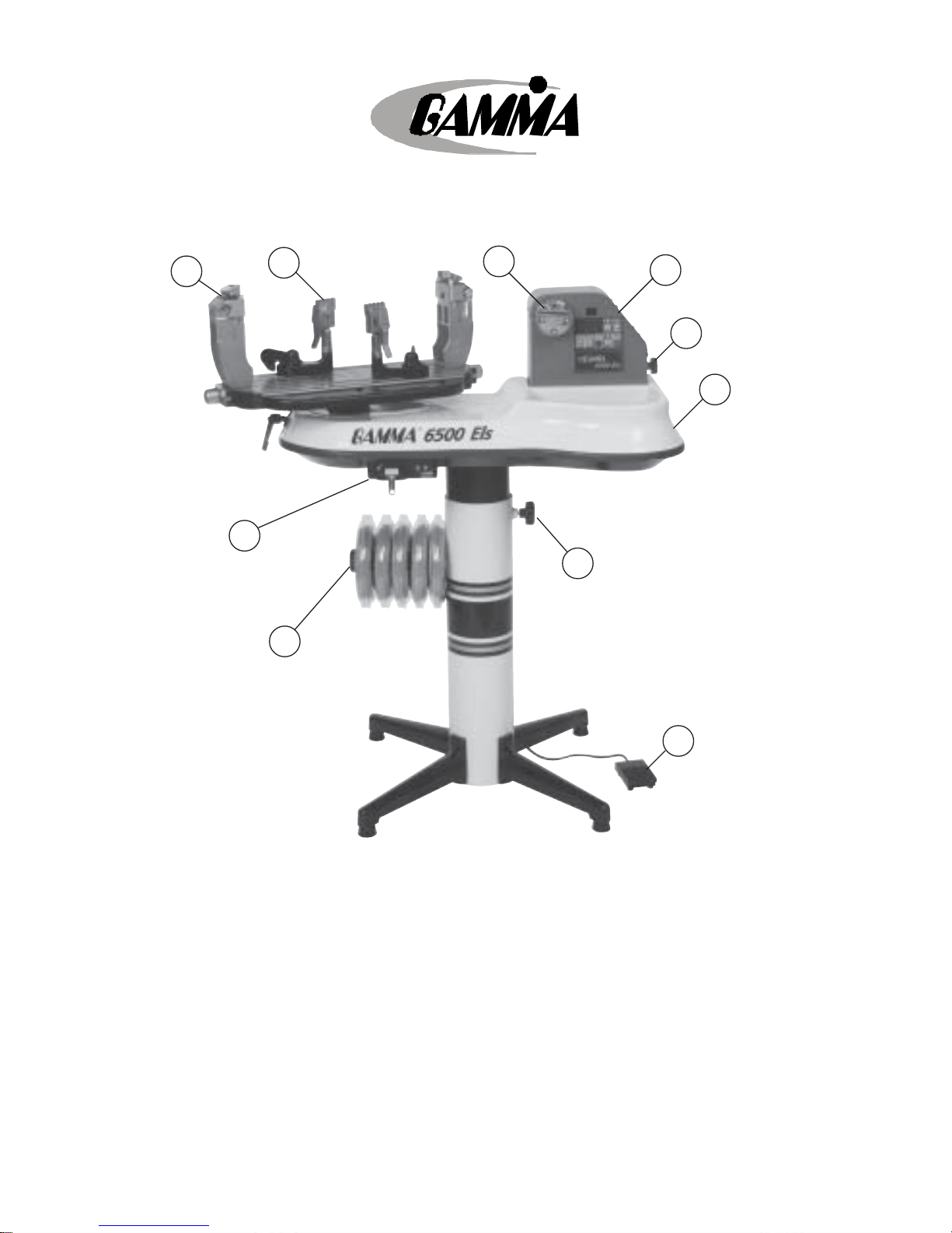
KEY PRODUCT FEATURES
1. Electric Constant Pull String Tensioner w/ Diamond Coated String Gripper
(10-90 lbs tension range in 0.5 lbs increments)
2. Control Panel w/ Calibration, Lbs/Kgs, Pulling Speed & String Length Functions
3. String Reel Holder
4. Electronic String Length Meter
5. 2-Point Self-Centering Mounting System (4 point support)
6. Quick Action Swivel, String Clamps w/ Diamond Coating
7. Convenient Foot Actuated Tensioner Switch
8. Fiberglass Cover w/ Integrated Tool Trays (70 sq. in. of storage area)
9. Height Adjustable from 39” to 46” (can also be used on table top)
10. 110 V / 220 V Compatibility
9
5
10
8
7
4
2
1
6
3

3
6500 Els
UNPACKING INSTRUCTIONS & CONTENTS
Instructions for Unpacking and Preparing for Assembly
The 6500 Els is shipped in three cartons, a large carton for the stringing machine and
accessories, a medium carton with the turntable and mounting system and a smaller
carton for the post and base legs. Please save the cartons and packing materials
for possible shipments in the future. Gamma Sports cannot be responsible for
machines that are not returned, in their original, undamaged packaging. The tools you will
need to assemble the 6500 Els are provided with the machine. Due to the weight of the
tensioner unit, you may need the assistance of someone to help lift the tensioner unit out
of the carton.
Once the cartons are opened, remove all inner cartons and check to be sure that all parts
are present and accounted for.
Contents of Base & Leg Carton
(1) Lower Post
(1) Upper Post with Flange Plate
(4) Legs
(1) Locking Knob Screw
(4) M8 x 25 Flat Head Screws
(4) M8 x 30 Cap Screws
(1) String Reel Holder (M8 Threaded Pin), (1) Knob, (10) Spacers, & (2) M8 Washers
(1) Box Wrenches – 6 & 12 mm
Contents of Turntable & Mounting System Carton
(1) Turntable
(2) Mounting Stands w/ Frame Hold Downs
(2) S tring Clamp Heads
Contents of Large Master Carton (including accessory cartons packed inside)
(1) Stringer Assembly Unit w/ Tensioner Module
(1) Power Cord w/ Ground Pin
(4) Rubber Feet w/ Screws
(1) Foot Pedal Tensioner Switch
(1) Face Plate for String Length Meter & (2) Spare String Length Meter Clamp Pads
(1) Tool Kit (contains side cutter, bent nose pliers, needle nose pliers)
(1) Straight Stringers Awl & (1) Pathfinder Specialty Awl
(1) St arting Clamp
(2) Composite Badminton Floating Clamps
(1) 9 pc L-Hex Wrench Set
(1) 17mm socket
(1) Gripper/Clamp Cleaning Stone
4
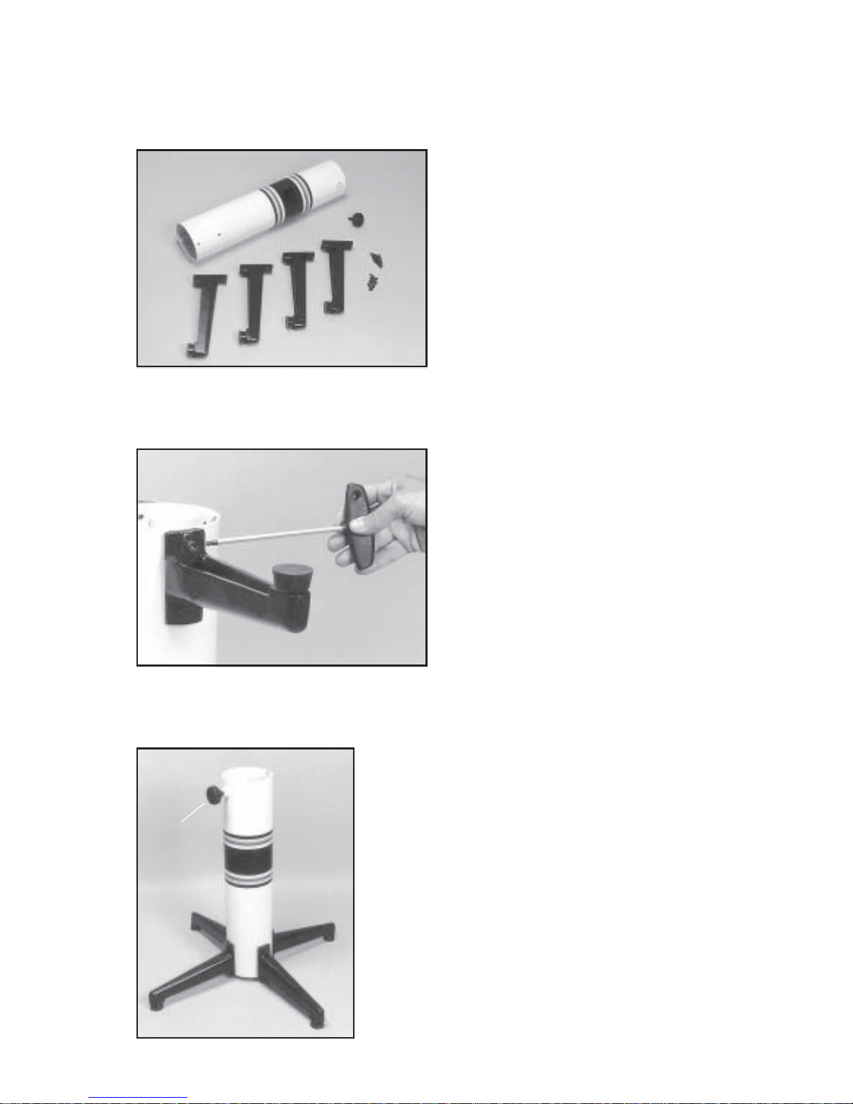
Base Leg Assembly
The stringing machine uses a four leg base
design. The legs must be assembled to the
support post before use. Remove the lower
column support, the upper column support,
four (4) legs, four (4) socket head cap screws
and four (4) flat head cap screws from the
small shipping carton.
Base Leg Assembly (Cont.)
Align the holes in the leg flange with the
matching holes in the lower column support
post. Secure the leg with one FLAT HEAD
cap screw through the upper hole, and one
SOCKET HEAD cap screw through the bottom hole. Repeat this procedure for the three
remaining legs.
ASSEMBLY INSTRUCTIONS
Base Leg Assembly (Cont.)
To complete the base stand, screw the height adjustment locking knob (“A”) into the side of the support
column. The locking knob should not protrude beyond
the inside of the support column at this time.
“A”
5
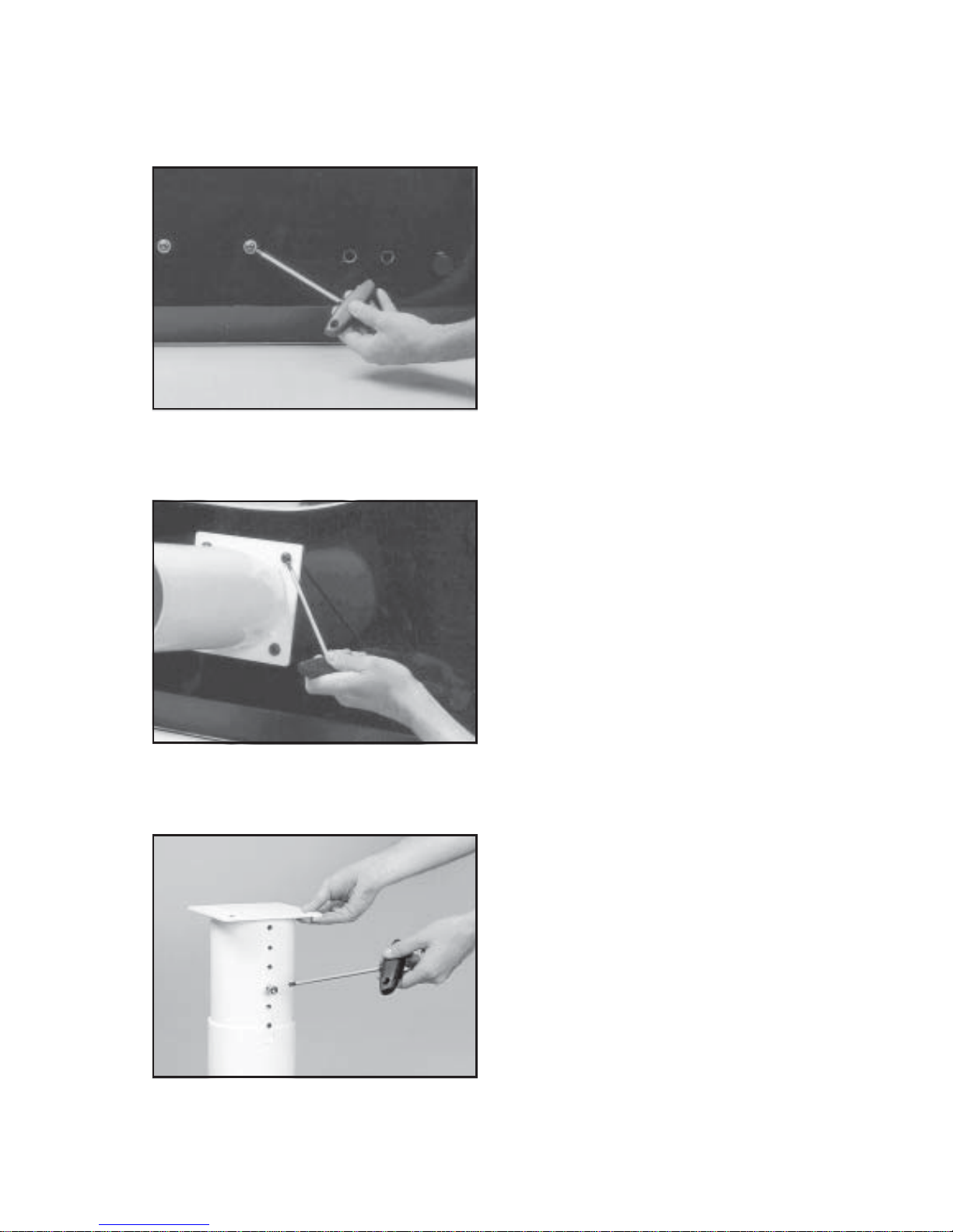
Stand Upper Post Installation
Remove the four (4) button head cap screws
from the base of the assembly.
ASSEMBLY INSTRUCTIONS
Stand Upper Post Installation (cont.)
With the height adjustment cap screw on the
upper post facing the left side of the tensioner,
align the four (4) holes in the upper post
flange with the holes in the tensioner base.
Secure the flange to the base with the four
cap screws.
Height Adjustment
The height of the machine is adjustable from
39” to 46”. To change the height, remove the
socket head cap screw from its current position and place it in the appropriate hole to set
the desired height of the machine.
6
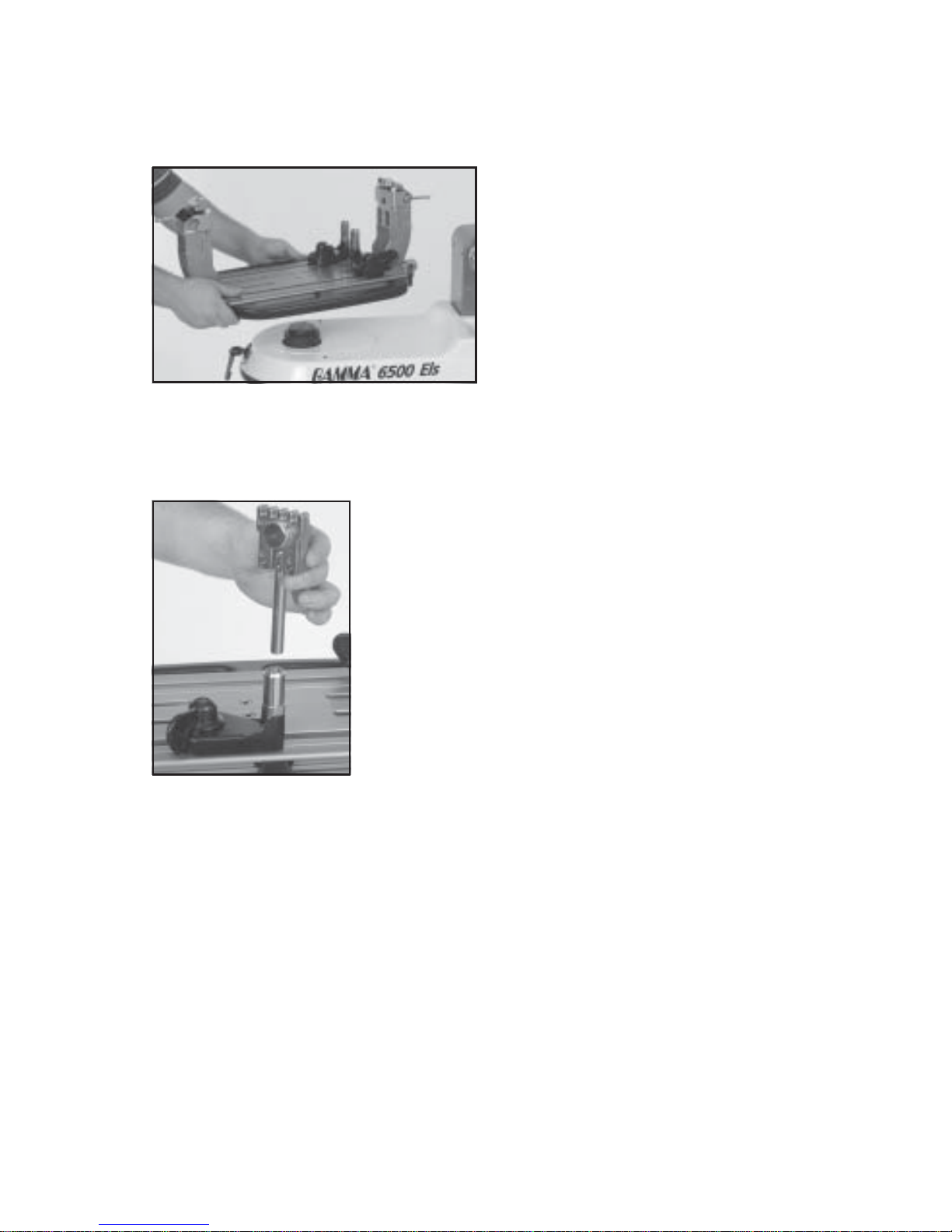
Clamp Head Installation
The post of the string clamp head and the tube of the string
clamp base are treated with grease to provide protection
against corrosion during shipping. Remove any excessive
grease with a clean cloth prior to use. The post and tube may
also be cleaned with isopropyl alcohol. After this type of
thorough cleaning, the post and tube should be treated with a
light coating of machine oil to protect the surfaces against
corrosion and to ensure smooth operation.
Installing the Turntable
Remove the nuts from underneath of the
turntable and leave the screws in position.
Align the four (4) holes in the center of the
turntable with the four (4) holes on the
turntable pin. Tighten them securely with the
6mm allen wrench.
ASSEMBLY INSTRUCTIONS
 Loading...