

Page 1
6004
STRINGING MACHINE
2 POINT SC MOUNTING
OWNER’S MANUAL
Issue 5C - February 2014
Page 2

6004
OWNER’S MANUAL
TABLE OF CONTENTS
WARRANTY ...............................................................................................PAGE 2
FEATURES.................................................................................................. PAGE 3
PACKAGE CONTENTS............................................................................... PAGE 4
ASSEMBLY INSTRUCTIONS .....................................................................PAGE 5
MOUNTING THE FRAME ........................................................................... PAGE 8
STRINGING THE FRAME ...........................................................................PAGE 9
ADDITIONAL FEATURES .........................................................................PAGE 12
PATHFINDER AWL ....................................................................................PAGE 13
MAINTENANCE & ADJUSTMENT ............................................................PAGE 14
TROUBLESHOOTING TIPS .................................................................... PAGE 17
PARTS LIST ............................................................................................ PAGE 18
PARTS DRAWING.....................................................................................PAGE 19
LIMITED WARRANTY
GAMMA SPORTS (“GAMMA”) warrants to the original purchaser that the GAMMA 6004 stringing machine (“EQUIPMENT”)
purchased is free from defects in materials and workmanship for a period of fi ve (5) years from the date of original purchase for
mechanical parts and for a period of one (1) year from the date of purchase for string clamps. Should any defects develop under
normal use within the specifi ed time periods, GAMMA will at its option, repair or replace the defective EQUIPMENT provided
it is returned to GAMMA prepaid at the purchaser’s expense. This warranty does not apply to any damage or defect caused
by negligence, abuse, misuse, unauthorized alteration, shipping, handling or part wear and tear as a result of normal use.
Routine maintenance, adjustment and cleaning required to ensure proper operation are the responsibility of the purchaser
and are not covered under the terms of this warranty. These include, but are not limited to: Linear Gripper Plate adjustment,
as described on page 10, String Clamp adjustment, as described on page 16, tension calibration, as described on page 14,
and Tensioner Brake adjustment, as described on page 15.
GAMMA’s obligation under this warranty is limited to repair or replacement of defective EQUIPMENT, and no one is authorized
to promise any other liability. GAMMA shall in no event be liable for any incidental or consequential damages.
To return defective EQUIPMENT, a return authorization (RA#) must be obtained from a GAMMA customer service representative by calling 1-800-333-0337. The RA# must be marked on the outside of the shipping carton being returned. All returns
must be shipped prepaid by the customer to GAMMA. Please retain the original shipping carton and packing materials for
any future shipments.
A GAMMA Care Service Plan is also available through GAMMA customer service, call 880.333.0337 for details.
2
Page 3
FEATURES
MACHINE FEATURES
Manual Spring Tension Winder with 11 to 89 lbs Tension Range
Patented Roller Guide for Maximum Accuracy and Consistency
Parallel Jaw Gripper with Diamond Dust Coated Gripping Surfaces
Professional Two Point Self-Centering Racquet Mounting System -
Accommodates All Racquets
Professional “Switch Action” Dual Action, Rotating, Metal Fixed
String Clamps with Diamond Dust Coating
Full 360 Degree Turntable Rotation
Large Convenient 141 sq. in. Tool Tray
Height Adjustable from 36” to 48”
3
Page 4

6004
Unpacking Instructions & Contents
Instructions for Unpacking and Preparing for Assembly
The stringing machine is shipped in two cartons, a Master carton has the stringing machine
fl oor stand, base legs, tensioner and accessories. The Mounting System Carton has the
turntable, clamps and mounting system. Please save the cartons and packing materi-
als for possible shipments in the future. Gamma Sports cannot be responsible for
machines that are not returned, shipped in their original, undamaged packaging. The tools
you will need to assemble the machine are provided with the machine.
Once the cartons are opened, remove all parts and check to be sure that all parts are present and accounted for.
Contents of Master Carton (MMU2-13)
(1) Lower Column Support Post
(1) Upper Column Support Post
(3) Short Legs w/ Adjustment Feet
(1) Long Leg w/ Adjustment Foot
(1) Bellows Set
(1) Tool Tray w/ Pad
(1) Tensioner Assembly
(1) Tensioner Track
(4) M8 x 25 Flat Head Screws
(4) M8 x 30 Cap Screws
(1) Tool Kit (contains side cutter, bent nose pliers & needle nose pliers)
(1) Straight Stringers Awl & (1) Pathfi nder Specialty Awl
(1) Tools for assembly and maintenance
Contents of Mounting System Carton (MMU2-68)
(1) Turntable Assembly w/String Clamp Bases and Mounting Stands
(2) String Clamps
4
Page 5
ASSEMBLY INSTRUCTIONS
Base Leg Assembly
The stringing machine uses a four leg base
design. The legs must be assembled to the
lower column support before use. This is
the larger of the two posts with the GAMMA
label. Align the holes in the leg fl ange with
the matching holes in the lower column
support post.
Secure the leg with one FLAT HEAD cap
screw through the upper hole, and one
SOCKET HEAD cap screw through the
bottom hole. Repeat this procedure for the
three remaining legs.
Base Foot Height Adjustment
Each foot of the Base Stand can be adjusted
to compensate for uneven surfaces.
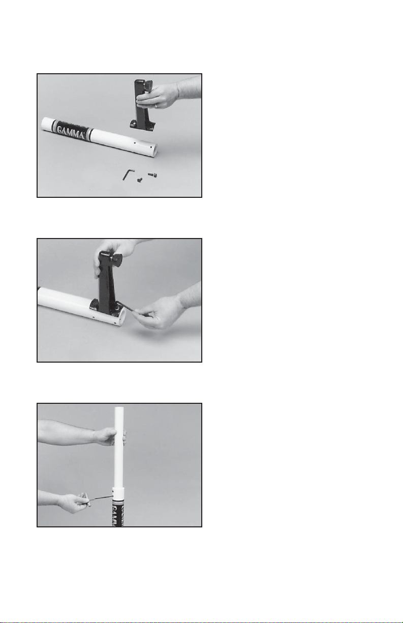
Upper Column Support Assembly
The upper column support is shipped inside
of the lower column support. Unloosen the
two set screws at the top of the lower column
support / base leg assembly. Extend the upper column to the maximum height and lock
in place with the two set screws located at
the top of the lower column support.
5
Page 6
ASSEMBLY INSTRUCTIONS
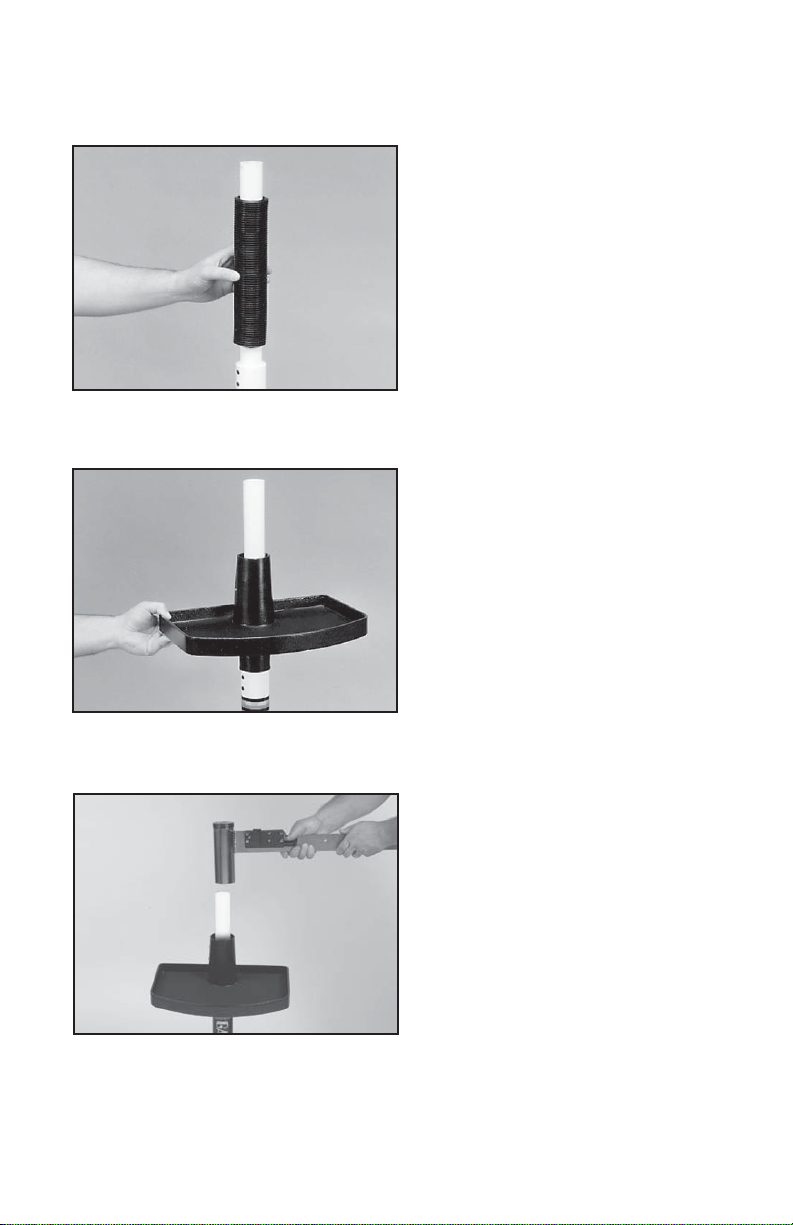
Bellows Installation
The bellows assembly is supplied in two
pieces and should be assembled as follows.
Place the bellows section with the fl ange over
the upper support column with the fl ange on
the top. Place the remaining bellows over
the upper support column and mate it with
the fl ange on the lower bellows.
Tool Tray Installation
Lower the tool tray over the top of the upper
column support and let it rest loosely on the
bellows assembly.
Tension Track Installation
Place the tube of the tension track assembly
over the top of the upper column support
and align the tension track with the long
leg of the base. Securely tighten the two
socket set screws on the tension track assembly tube, locking it to the upper column
support. Align the notch in the tool tray with
the tension track bar while raising the tool
tray. Secure the tray with the set screws in
the side of the tray casting.
6
Page 7

ASSEMBLY INSTRUCTIONS
Turntable and Mounting System
Installation
To install the turntable position the turntable
over the turntable pin and align the bolts,
located in the poly bag, with the holes in
the fl ange. Secure them with the included
hex wrench.
String Clamp Installation
The post of the string clamp and tube of the
string clamp base are treated with grease to
provide protection against corrosion during
shipping. Remove any excessive grease with
a clean cloth prior to use. The post and tube
may also be cleaned with isopropyl alcohol.
After this type of thorough cleaning, the post
and tube should be treated with a light coating
of machine oil to protect the surfaces against
corrosion and to ensure smooth operation.
Tensioner Installation
Remove the button head screw and washer
located at the end of the tensioner bar with
the 3mm hex wrench provided. Slide the
tensioner onto the bar, being careful to align
the bar with all of the bearings and the drive
gear with the gear track. Replace the button
head screw and washer in the end of the
tensioner bar.
7
Page 8

ASSEMBLY INSTRUCTIONS
Height Adjustment
The turntable height can be adjusted to suit
the stringer. To adjust, loosen the two set
screws on the lower column support post
below the bellows assembly. Adjust the
amount of engagement between the upper
and lower column supports until the desired
height is attained. Make sure that the tension
track is still aligned with the long leg of the
base and tighten the two set screws to lock
the upper support column into place.
MOUNTING THE FRAME
Adjusting the Inner Racquet Supports
The white racquet supports are adjustable to accommodate
all racquets and provide maximum support to the racquet
frame. Screw the pads up or down so they contact the
frame at a maximum height without blocking the grommet
holes.
Mounting Stand Adjustment
When mounting a racquet, adjust the
Mounting Stands so that the white Racquet
Supports on top of the Mounting Stands fi t
inside the hoop of the racquet. Lower the
racquet over the Racquet Supports and adjust the Mounting Stands until the supports
just make contact with the inside surface of
the racquet at the head and throat. There is
an arrow on the face of each knob indicating the turning direction that will “Tighten”
the mounting points by moving the 2pt
Racquet Supports closer to the inside surface of the racquet at the head and throat. Turning
the knobs in the opposite direction will move the Mounting Stands closer together and will
allow the Racquet Supports to move away from the racquet frame.
Mounting Stands further apart to bring the
8
Page 9

MOUNTING THE FRAME
Racquet Hold Down Clamp Operation
With the lever in the up position, insert the
racquet hold down clamp pin into the hole in
the center of the mounting stand. Lower the
hold down clamp until it just makes contact with
the surface of the racquet. Using slight palm
pressure on the hold down clamp depress the
racquet hold down lever completely to secure
the racquet frame to the stand.
Special Throat Mounting
Racquets with a bridge that is thinner than the
rest of the frame or are tapered from head to
throat require special mounting to ensure the
frame is not damaged. The white support pads
need to be moved from the inside of the racquet
bridge to the throat of the racquet.
BRIDGE
STRINGING THE FRAME
Clamp Base Operation
Rotate the base locking lever clockwise
to secure the clamp base to the turntable.
Reverse the clamping procedure to unlock
the string clamp. The locking lever is spring
loaded to assist the unlocking of the clamp
base.
The locking lever should be tightened enough
to prevent clamp base slippage on the turntable, when the desired tension is placed on
the string. To go from the loose position to
requires the travel permitted by the clamp base. If the travel is not suffi cient to allow smooth
operation adjust the clamp base as outlined on page 16.
the clamped position and back, generally
9
Page 10

STRINGING THE FRAME
String Clamp Operation
The string clamps are of a dual action
design where the string clamp and clamp
base operate independently of one another.
To clamp a string, lift the clamp head and place
the string between the jaws and depress the
clamp head lever to secure the string. The
clamping pressure applied to the string should
be adjusted to provide suffi cient pressure
to secure the string when subjected to the
desired pulling tension. The diamond coated
between the clamps and the string to allow for reduced clamping pressure while securing and
holding the string under tension.
Note that excessive pressure can damage both the strings and String Clamp.
knob counterclockwise until the “1” or “2” mark on the knob aligns with the line on the knob
support. To decrease tension by 1 or 2 lbs, turn the knob clockwise until the “2” or “1” mark
on the knob aligns with the line on the knob support.
gripper plates provide for increased friction
Setting Tension
The spring tensioner utilizes a rotary adjusting knob along with a linear tension scale
to indicate the tension setting. The scale is
divided into 3 lb. increments and each 1/3
turn of the tension knob changes tension
by 1 lb. To set the desired tension, rotate
the tension knob and align the mark on the
spring guide with the desired tension setting
on the scale. When the “0” mark on the knob
aligns with the line on the knob support the
tension will be that indicated on the scale.
To increase tension by 1 or 2 lbs turn the
Setting the Gripper Jaw Spacing
The gripper jaws of the tensioner are adjustable to accommodate varying string gauges.
If the string slips through the gripper jaws
while pulling tension, rotate the gripper jaw
adjustment screw counter-clockwise.
If the string is damaged while pulling tension,
rotate the gripper jaw adjustment screw
clockwise.
The jaws will be properly adjusted when
there is enough pressure to securely grip the
string without causing damage to the string.
10
Page 11

STRINGING THE FRAME
Tensioner Travel Stop
To prevent contact between the tension
head and the racquet and/or turntable, a
travel stop is located about midpoint along
the tensioner bar below the gear track. In
the event the tension head must be moved
closer to the racquet, pull and turn the travel
stop 90 degrees. To re-engage the travel
stop, simply pull and turn the travel stop
Travel Stop
are handy for holding the loose end of the string while tensioning the string. Simply insert the
loose end into the tear drop shaped holes and slide the string toward the point of the hole.
90 degrees.
Getting Started
To begin stringing the main strings, thread
the two ends of the string through the two
center holes at the appropriate end of the
frame and continue through the opposite
center holes. Thread one end of the string
through the adjacent grommet hole and pull
excess by hand.
Secure one of the strings using a string clamp.
Handy tip: The tear drop shaped holes
towards the back of the shoulder supports
Pulling Tension
Wrap the loose section of string once around
the roller and insert the string between the
diamond dust coated string gripper plates.
Pull the string perpendicular to the gripper
plates while slowly rotating the tensioner
crank clockwise until the brake lever pops
out of the latching block. The string is now
tensioned and can be clamped in place with
the remaining fi xed clamp.
Repeat the above steps until all main strings
are installed. Tie off ends of main strings
as per racquet manufacturers recommendations.
11
Page 12

STRINGING THE FRAME
loosening the mounting stands.
ADDITIONAL FEATURES
Clamping the First Main String
Secure the tensioned main string using the
remaining fi xed clamp. Repeat the procedure
for all of the remaining main strings and
tie off following the racquet manufacturers
recommendations.
Follow the manufacturer’s recommended
stringing pattern for one or two piece
stringing. This will determine the starting
point for the cross strings. If applicable, tie
the fi rst cross string using an appropriate
starting knot.
Weaving the Cross Strings
Weave the cross strings over and under the
main strings being careful to alternate the
weave direction of each consecutive cross
string so as to be opposite of the previously
installed cross string.
Once the fi nal cross string is tensioned
and clamped, tie off at the appropriate hole
specifi ed by the racquet manufacturer. Remove the frame from the mounting system
by releasing the racquet holddowns and
Locking the Turntable
The turntable may be locked in any position.
Rotate the lever down to lock the turntable
and up to release the turntable.
12
Page 13

PATHFINDER AWL
The machine includes the pathfi nder stringing awl which creates a pathway between
or around strings to make inserting a string
through blocked grommets easier and
quicker.
Insert the awl through the grommet hole in
the same manner as for traditional awls. The
pathfi nder awl must be in the closed position
before insertion.
Once the awl is inserted, pull the handle of
the awl outward while holding the tip section
in place. This leaves the outer sheath in the
grommet hole. Insert the end of the string
into the outer sheath.
While holding the string, slowly pull the sheath
out of the grommet hole to leave the free end
of the string exposed.
13
Page 14

MAINTENANCE & ADJUSTMENTS
Tension Calibration Procedure
Set the tension to 60 lbs. as indicated by
the linear scale and rotary knob. Place the
string on one end of a tension calibrator
into a string clamp and secure. Place string
located on the other end of the calibrator
into the string tensioner and apply tension.
If the brake lever releases before or after 60
lbs., the tension head should be calibrated
as follows.
Loosen the 1.5 mm locking set screw (A)
located on the side of the latching block as
A
shown. The set screw is used to hold the
adjustment screw in place.
If the lever releases before 60 lbs., using
the supplied L-shaped hex wrench, turn
B
the adjustment screw (B) located on the
left side of the latch block counter-clockwise
to increase the engagement of the brake
release latch with the brake lever. Repeat
step 1 and adjust until the correct tension
is indicated on the calibrator.
If the tension indicated in step 1 is greater
than 60 lbs., turn the adjustment screw
clockwise to reduce the engagement of the
brake release latch with the brake lever.
Repeat step 1 and adjust until the correct
tension is indicated on the calibrator.
14
Page 15

MAINTENANCE & ADJUSTMENTS
Adjusting the Tensioner Brake
After stringing many racquets, the brake
of the tensioner may need to be adjusted.
With the brake lever engaged in the latch,
A
B
insert the 5mm hex wrench into the set
screw (A) located at the base of the brake
lever. It can be accessed through the hole
on the face of the tensioner cover (above
the ‘GAMMA’ logo).
Note: The tensioner cover does not need
to be removed for the adjustment. The
cover has been removed in the pictures for
illustration purposes.
While holding the 5mm brake lever adjustment set screw (A), loosen the bolt (B) located
on the back side of the tensioner frame with
the 4 mm hex wrench.
Note: Bolt (B) should only be loosened and
should not be completely removed.
To tighten the braking mechanism, turn the
set screw (A) counter clockwise by about 1/8
turn. Re-tighten the bolt (B) on the back side
of the tensioner frame and check for brake
tightness. The tensioner should move freely
along the track with the brake lever engaged
and should hold tension with the brake lever
released. If more adjustment is needed,
repeat steps above until properly adjusted.
15
Page 16

MAINTENANCE & ADJUSTMENTS
String Clamp Adjustment
The string clamps will need minor adjustments according to string type, construction,
and gauge.
To adjust the gap (clamping pressure)
between the clamp jaws, insert the string
through the racquet as if you were beginning
Adjustment
Knob
or damages the string, it may be excessively tight and should be adjusted by turning the
Adjustment knob counter clockwise to open the gap between the jaws.
NOTE: Due to the bearings used in the Clamp Lever the action of the Clamp Lever is
very light making it easy to apply excessive clamping pressure. Clamps that are set
too tight can damage the string as well as the string clamp jaws.
The clamp jaws should be cleaned periodically to be free from dirt, oil, and any string coating
for them to grip properly.
the main strings. Clamp the string and pull
tension. If the string slips through the jaws of
the clamp, tighten the clamp by compressing
the clamp jaws together by hand while turning the Adjustment Knob, in the clockwise
direction. If the clamp leaves impressions
Switch Action Clamp Base Adjustment
If the Switch Action clamp bases slip on the
turntable, the base locking levers may need
adjusted. Turn the hex screw clockwise to
tighten the clamp and counterclockwise to
loosen. If frequent adjustment is needed,
remove the adjustment screw and tighten the
two screws underneath of the clamp. Re-install
the adjustment screw.
Switch Action Clamp Base Removal
If the Switch Action clamp base needs to be
removed, undo the 2 screws holding the FRP
stop, underneath of the turntable. Remove
the FRP stop and clamp for cleaning, adjustment or replacement.
16
Page 17

2pt Hold Down Clamp Adjustment
The 2pt hold down clamps have been adjusted at
the factory. However, depending on the racquet
frame thickness, the hold down clamp may require
adjustment. Use a 3 mm hex wrench and turn the
set screw clockwise to reduce the hold down clamp
pressure and counter clockwise to increase the hold
down clamp pressure.
Note: To avoid potential damage to the racquet
only make small adjustments at a time by slightly
turning the set screw by no more than 1/4 of a turn.
Test the hold down lever to insure the racquet is
held snuggly but without applying excessive force
to the lever.
Periodically clean the hold down clamp pin using rubbing alcohol to remove residue or dirt,
that may build up over time.
TROUBLESHOOTING TIPS
PROBLEM SOLUTION
String slips in clamps - Adjust gap between clamp jaws
- Clean clamp jaws
String slips in gripper - Clean gripper jaws
- Adjust gripper jaw stop screw
String clamp base slips on turntable - Clean bottom of clamp & top of turntable with
alcohol
- Adjust clamp base locking nut
String tension too tight or too loose - Check tension using a tension calibrator,
adjust machine calibration if necessary
CARE & CLEANING
With time and use, the clamping surfaces of your machine may become oily or dirty and
result in string or clamp slippage while stringing. Periodic cleaning of the String Clamps,
String Clamp Base and String Gripper is recommended. Knife sharpening stones work well
for cleaning the diamond coated string clamping surfaces. Cleaning with a solvent such as
isopropyl alcohol and a mild abrasive tool such as a toothbrush also works well to remove
oily or greasy build up.
17
Page 18

PARTS LIST
PART # DESCRIPTION TOOLS & ACCESSORIES
6B CAP SCREW- M8x30
104A TENSIONER ASSEMBLY
105 RETAINER SCREW
112 TOOL TRAY
113 LONG LEG
114 SHORT LEG
115 FLAT HEAD SCREW- M8x25
116 LOWER COLUMN SUPPORT
119 BELLOWS
120A UPPER COLUMN SUPPORT
121 LEVELING FOOT
165 SET SCREW- M8x10
203 TT SCREWS*
283 TT END CAP
285 TT END CAP- RIGHT
286 TT END CAP- LEFT
289 TT HANDLES
304 SC TT KNOB
309 2 PT PAD
310 2 PT HOLD DOWN
311 2 PT RQT SUPPORT
312 2 PT LEVER
313 2 PT MOUNTING STAND
314 2PT MOUNTING ASSY
315 2 PT GRABBER PLATE
320 BRAKE RING
327 TT PIN
336 WINDER BAR
337 BRAKE BOX
362 SC TURNTABLE TT9-2PT
389 2PT TOP CAP w/ADJ SCREW
390 2 PT STICKER
MDSCS13 UNIV DIECAST STRING CLAMP
MSAC11 SA CLAMP BASE TT7/TT8
98 10MM WRENCH*
109 NEEDLE NOSE PLIERS*
110 BENT NOSE PLIERS*
171 DIAGONAL CUTTERS*
251 HEX WRENCH SET*
MA STRINGER’S AWL*
MPG STARTING CLAMP*
MPS CLEANING STONE*
MPSA PATHFINDER AWL*
MGSMC MACHINE COVER *
* (NOT SHOWN)
OPTIONAL TOOLS & ACCESS
MFSC FLOOR STAND CASTERS
MTC CALIBRATOR
SGSM STRINGER’S MAT
18
Page 19

327
PARTS DRAWING
104A
112
165
120A
116
119
165
115
337
336
390
113
MSAC11
314
362
105
121
MDCSC13
315
313
310
311
309
389
312
283
285
304
286
289
320
114
6B
19
Page 20

MMU2-79
(MG632-14)
GAMMA SPORTS
200 Waterfront Drive
Pittsburgh, Pennsylvania 15222
Phone: 800.333.0337 Fax: 412.323.0317
Visit our website at www.gammasports.com
Copyright 2014 GAMMA Sports - All Rights Reserved
 Loading...