

Page 1
OWNER'S MANUAL
Issue 3 - June 20, 1998
6002
STRINGING MACHINE
Copyright 1998 GAMMA Sports - All Rights Reserved
Page 2

1
TABLE OF CONTENTS
LIMITED WARRANTY
GAMMA SPORTS ("GAMMA") warrants to the original purchaser that the GAMMA stringing machine ("EQUIPMENT") purchased is free from defects
in materials and workmanship for a period of five (5) years from the date of original purchase for mechanical parts (excluding string clamps), and for
a period of one (1) year from the date of purchase for string clamps. Should any defects develop under normal use within the specified time periods,
GAMMA will at its option, repair or replace the defective EQUIPMENT provided it is returned to GAMMA prepaid at the purchaser's expense. This
warranty does not apply to any damage or defect caused by negligence, abuse, misuse, unauthorized alteration, shipping, handling, or part wear
and tear as a result of normal use.
GAMMA's obligation under this warranty is limited to repair or replacement of defective EQUIPMENT, and no one is authorized to promise any other
liability. GAMMA shall in no event be liable for any incidental or consequential damages.
To return defective EQUIPMENT, a return authorization (RA#) must be obtained from a GAMMA customer service representative by calling 1-800333-0337. The RA# must be marked on the outside of the shipping carton being returned. All returns must be shipped prepaid by the customer to
GAMMA. Please retain the original shipping carton and packing materials for any future shipments.
6002
OWNER'S MANUAL
PAGE 1................................................................................................WARRANTY
PAGE 2 ...................................................................................................FEATURES
PAGE 3 ....................................................................... ASSEMBLY INSTRUCTIONS
PAGE 9 .............................................................................. MOUNTING THE FRAME
PAGE 11 ............................................................................STRINGING THE FRAME
PAGE 13 .................................................................................... PATHFINDER AWL
PAGE 14 ....................................................... MAINTENANCE AND ADJUSTMENTS
PAGE 16 .................................................................................TROUBLESHOOTING
PAGE 16 .............................................................................. CARE AND CLEANING
PAGE 17 .................................................................. COMPONENT IDENTIFICATION
PAGE 18 ......................................................................................... PARTS LISTING
Page 3
2
FEATURES
Manual Spring Tensioner
Diamond Coated String Gripper
Tension Range: 11lbs. - 89lbs.
6 Point Suspension Mounting System ( 10 Point Support )
Diamond Coated Dual Action Swivel Composite String Clamps
Full 360 Degree Turntable Rotation
Precision Bearing Mounted Turntable
Large Convenient 141 sq. in. Tool Tray
Height Adjustable From 36” to 48”
Page 4
3
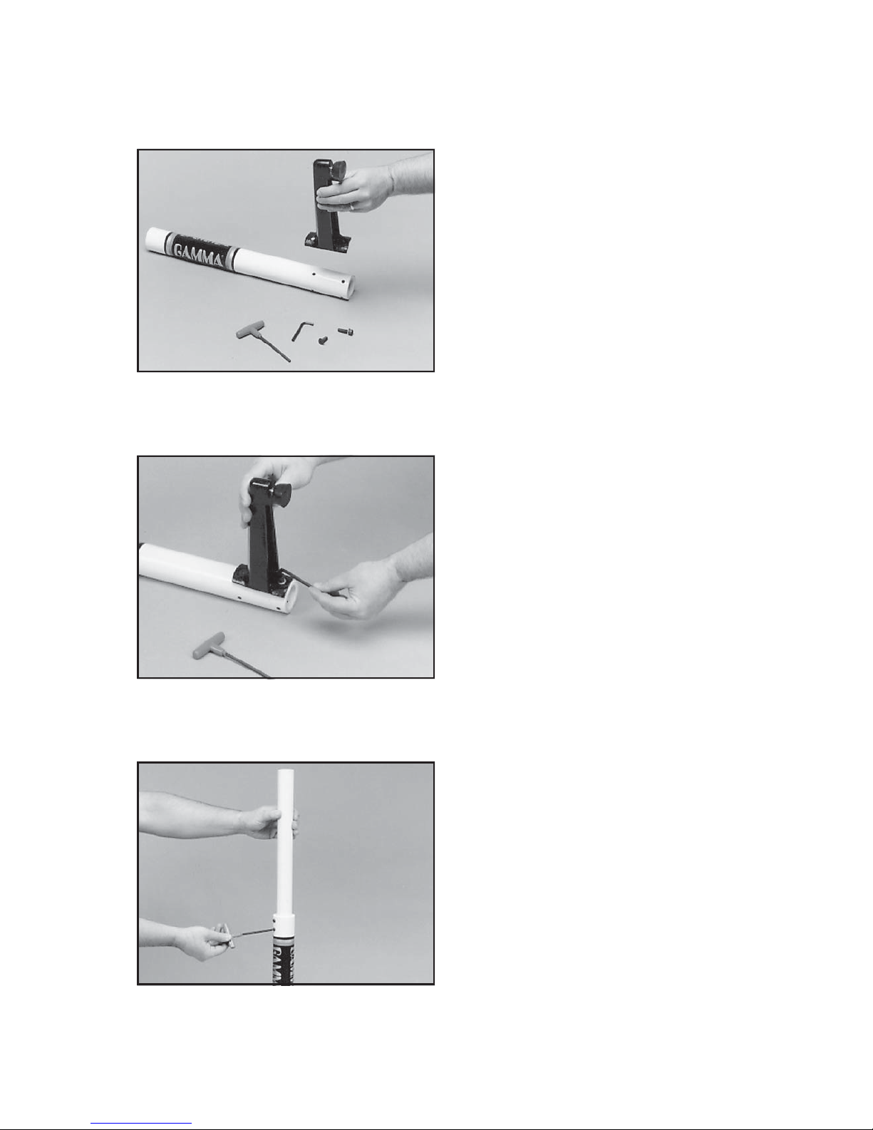
Base Leg Assembly
The GAMMA 6002 stringing machine uses a
four leg base design. The legs must be
assembled to the support post before use.
Remove the lower column support from the
carton. This is the larger of the two posts and
has the GAMMA label.
Align the holes in the leg flange with the
matching holes in the lower column support
post. Secure the leg with one FLAT HEAD
cap screw through the upper hole, and one
SOCKET HEAD cap screw through the bottom hole. Repeat this procedure for the three
remaining legs.
Upper Column Support Assembly
Insert the upper column support into the
lower column support / base leg assembly.
Leave the upper column extended to maximum height and lock in place with the two set
screws located at the top of the lower column
support.
ASSEMBLY INSTRUCTIONS
Page 5
4
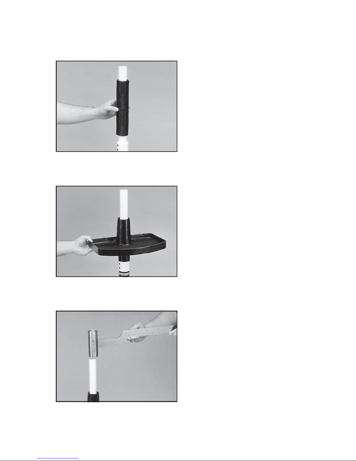
Bellows Installation
The bellows assembly is supplied in two
pieces and should be assembled as follows.
Place the bellows section with the flange over
the upper support column with the flange on
the top. Place the remaining bellows over the
upper support column and mate it with the
flange on the lower bellows.
Tool Tray Installation
Lower the tool tray over the top of the upper
column support and let it rest loosely on the
bellows assembly.
Tension Track Installation
Place the tube of the tension track assembly
over the top of the upper column support.
Align the tension track with the long leg of the
base assembly. Securely tighten the two
socket set screws on the tension track assembly tube, locking it to the upper column
support. Align the notch in the tool tray with
the tension track bar while raising the tool
tray. Secure the tray with the set screws in the
side of the tray casting.
ASSEMBLY INSTRUCTIONS
Page 6
5
ASSEMBLY INSTRUCTIONS
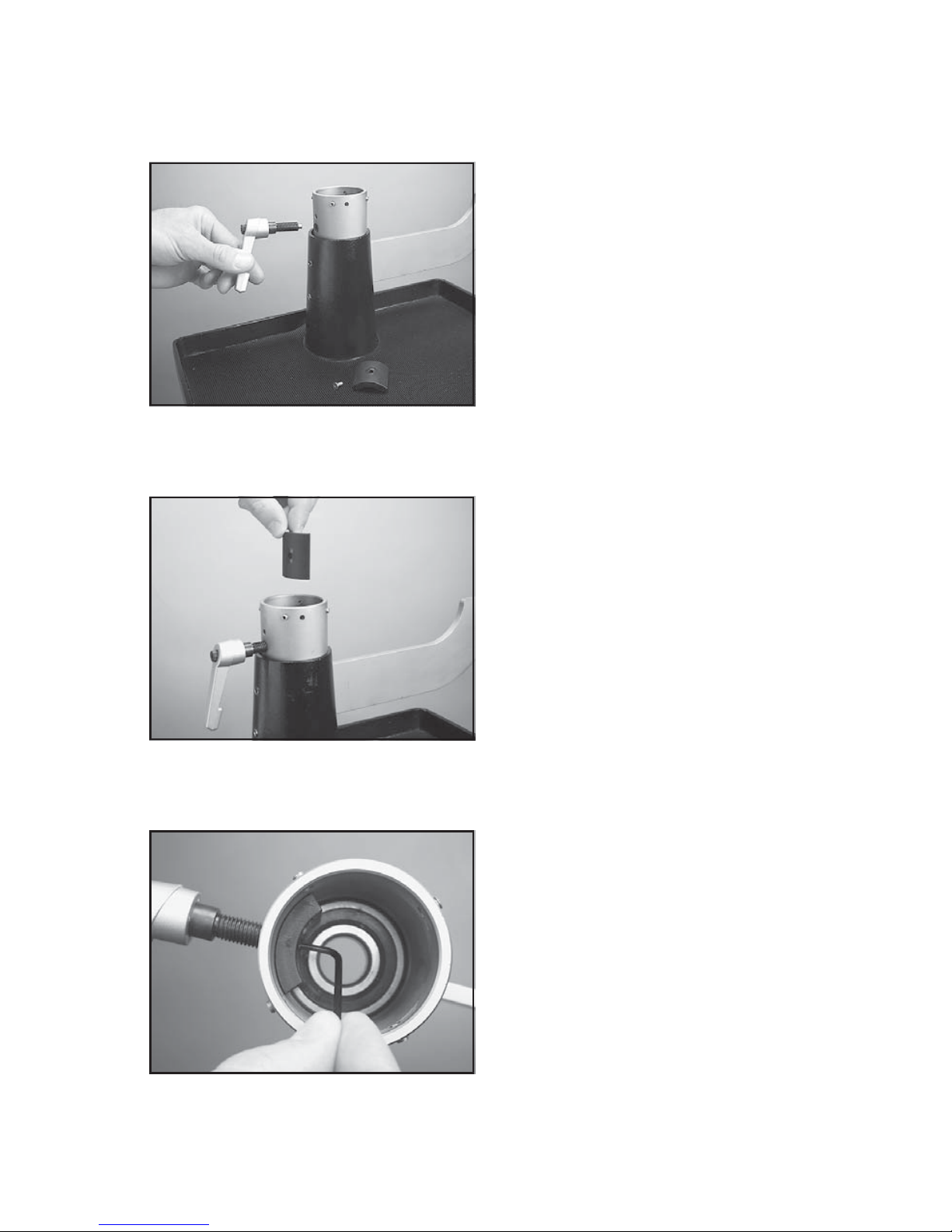
Turntable Brake Installation
Remove the flat head screw from the end of
the brake lever bolt and install the brake lever
bolt into the threaded hole located on the side
of the turntable tube.
Place the brake pad into the turntable tube,
then insert the end of the brake leverbolt into
the hole of the brake pad so that the brake
pad rests on the shoulder of the bolt.
Insert the flat head screw into the end of the
brake lever bolt from the inner side of the
brake pad. While holding the head of the
screw with the 2.5mm L-shaped wrench,
turn the lever bolt to secure the brake pad
against the shoulder of the lever bolt and set
the head of the screw below the inner
surface of the brake pad. turn the lever to
retract the pad until it sets against the inner
surface of the turntable tube to provide
clearance for installation of the turntable.
Page 7

6
Retract the four set screws around the top
of the turntable tube to provide clearancefor
installing the turntable. Carefully lower the
turntable into the tube until it seats fully into
the tube and rests against the bearing located at the botom of the tube.
ASSEMBLY INSTRUCTIONS
Tighten the four set screws located at the
top of the turntable tube until they contact the
bearing located on the turntable pin. Tighten
the screws in a crossing pattern from one
side to the next to keep the bearing on the
turntable pin centered in the tube.
Page 8

7
ASSEMBLY INSTRUCTIONS
Installing the Fixed Clamps
To install the clamps, remove the winged lock
knob to separate the knob from the lower
guide bushing. Be careful not to lose the
thrust bearing components located in the
center recess of the knob.
Align the clamp base with the clamp slot of
the turntable base. Insert the clamp guide
bushing into the clamp from the bottom of the
turntable making sure to engage the guide
with the clamp slot.
Place the load bushing into the top of the
clamp base mating it to the lower guide
bushing.
After checking that the thrust bearing is positioned correctly in the base of the winged lock
knob, screw the knob into the base bushing
until fully seated.
Support Post Installation
The support post assemblies are precision
aligned at the factory and are marked for
proper installation on the turntable.
Install the marked support post on the marked
side of the turntable. Align the threaded hole
in the bottom of the support post with the slot
in the turntable. Screw the lever lock bolt with
washer into the bottom of the support post
and tighten gently.Position the washer with
the rounded edge toward the turntable.
Repeat procedure on the opposite side.
Page 9

8
ASSEMBLY INSTRUCTIONS
Installing the Tensioner
Remove the button head screw and washer
located at the end of the tensioner bar with
the 3 mm hex wrench provided. Slide the
tensioner onto the bar, being careful to align
the bar with all of the bearings and the drive
gear with the gear track. Replace the button
head screw and washer in the end of the
tensioner bar.
Installing the Crank Arm
Remove the flat head screw located on the
crank shaft with the 2.5mm wrench provided.
Slide thecrank handle over the crank shaft
while aligning the holes. Replace the flathead screw.
T ravel Stop
Note: The tensioner bar is equipped with a
tensioner travel stop screw to limit travel of
the tensioner along the bar and prevent contact between the tensioner and the racquet
mounting system while stringing. The stop
screw is located about midpoint along the
tensioner bar below the gear track. To engage the stop, turn the stop screw clockwise
until fully seated against the bar. To disengage the stop screw, turn it counter clockwise until it no longer protrudes beyond the
surface of the bar.
Page 10

9
Adjusting the Frame Support Posts
Place the racquet frame over the center
support slide and onto the frame support.
Loosen the lever lock bolt on one support
post. Slide the post outward until the center
support of the racquet support slide is positioned near the inside surface of the racquet
frame. Securely tighten the lever lock bolt.
Adjust the opposite post using the same
procedure.
Caution: To avoid racquet damage, the support slide should not contact the racquet prior
to fixing the support posts.
Height Adjustment
The turntable height of the GAMMA 6002 can
be adjusted to suit the stringer. To adjust,
loosen the two set screws on the lower column support post below the bellows assembly. Adjust the amount of engagement between the upper and lower column supports
until the desired height is attained. Make sure
that the tension track is still aligned with the
long leg of the base and tighten the two set
screws to lock the upper support column into
place.
Shoulder Support Adjustment
The shoulder supports on the GAMMA 6002
are adjustable to provide support to the
racquet frame. Loosen the knurled knob at
the bottom of the shoulder support and swivel
the support so that the pads will contact the
frame squarely when the arms are closed
against the racquet. Should the shoulder
supports block string holes, adjust the position of the racquet between the arms until the
shoulder supports contact the racquet between grommet holes.
MOUNTING THE FRAME
Page 11

10
MOUNTING THE FRAME
Securing the Shoulder Supports
Secure the racquet frame with the shoulder
supports by rotating the large adjustment
knobs on the outside of the support post
assemblies clockwise. Adjust the supports
until firm contact is made between the shoulder supports and the frame.
The tear drop shaped holes torwards the
back of the shoulder supports are handy
for holding the loose end of the string
while pulling the string through the
racquet. Simply insert the loose end into
the tear drop shaped holes and slide the
string into the point of the hole.
Support Slide Adjustment
Once the frame support posts are secured,
lightly tighten the support slides by turning
the knobs on the outside of the slides clockwise. Adjust the slides in equal increments
until slight resistance is felt.
Apply a final adjustment to all racquet support points until the racquet is firmly secured
in the mounting system.
Should the frame supports lose contact with
the frame while stringing, they should be
adjusted, as needed, to maintain contact with
the frame.
Page 12

11
Setting Tension
The GAMMA 6002 utilizes a rotary adjusting
knob along with a linear tension scale to
indicate the tension setting. The scale is
divided into 3 lb increments and each 1/3 turn
of the tension knob changes tension by 1 lb.
To set the desired tension, rotate the tension
knob and align the mark on the spring guide
with the desired tension setting on the scale.
When the “0” mark on the knob aligns with the
line on the knob support the tension will be
that indicated on the scale. To increase tension by 1 or 2 lbs turn the knob counterclock-
wise until the “1” or “2” mark on the knob
aligns with the line on the knob support. To decrease tension by 1 or 2 lbs, turn the knob
clockwise until the “2” or “1” mark on the knob aligns with the line on the knob support.
Fixed Clamp Operation
The fixed clamps supplied with your GAMMA
6002 are of a dual action design. The string
clamp and the clamp base operate indepen-
dently of one another.
To clamp a string, lift the clamp head and
place the string between the jaws. Depress
the clamp head lever to secure the string.
Fixed Clamp Operation
Rotate the winged lock knob clockwise to
secure the clamp base to the turntable.
Reverse the clamping procedure to un-clamp
the string.
Note: If the string slips in the string clamp
while tensioning, adjust the gap between the
clamp jaws as per the instructions on page
14.
STRINGING THE FRAME
Page 13

12
STRINGING THE FRAME
Pulling Tension
Wrap the loose section of string once around
the DIABLO and insert the string between the
diamoind dust coated string gripper plates.
Pull the string perpendicular to the gripper
plates while slowly rotating the tensioner
crank clockwise until the brake lever pops out
of the latching block. The string is now
tensioned and can be clamped in place with
the remaining fixed clamp.
Repeat the above steps until all main strings
are installed. Tie off ends of main strings as
per racquet manufacturers recommenda-
tions.
Weave the cross strings over and under the
main strings being careful to alternate the
weave direction of each consecutive cross
string so as to be opposite of the previously
installed cross string.
Once the final cross string is tensioned and
clamped, tie off at the appropriate hole speci-
fied by the racquet manufacturer.
Clamping the First Main String
To begin stringing the main strings, thread
the two ends of the string through the two
center holes at the appropriate end of the
frame and continue through the opposite
center holes. Thread one end of the string
through the adjacent grommet hole and pull
excess by hand.
Secure one of the strings using a string
clamp.
Page 14

13
PATHFINDER AWL
The GAMMA 6002 includes the new Path-
finder stringing awl which creates a pathway
between or around strings and through tight
grommets.
Insert the awl through the grommet hole in
the same manner as for traditional awls. The
Pathfinder awl must be closed before inser-
tion.
Once the awl is inserted, pull the handle of
the awl outward while holding the tip section
in place, leaving the outer sheath in the
grommet hole.
Insert the end of the string into the center of
the sheath.
While holding pressure on the string, slowly
pull the sheath out of the grommet hole to
leave the end of the string exposed.
Page 15

14
MAINTENANCE
Tension Calibration Procedure
Step 1
Set the tension to 60 lbs. as indicated by the
linear scale and rotary knob. Place the string
on one end of a tension calibrator into a string
clamp and secure. Place string located on
the other end of the calibrator into the string
tensioner and apply tension. If the brake
lever releases before 60 lbs. or after 60 lbs.,
the tension head should be calibrated as
follows.
Tension Calibration Procedure
Step 2
Loosen the plastic locking screw (A) located
on the side of the latching block as shown.
The plastic screw is used to hold the adjust-
ment screw in place.
Tension Calibration Procedure
Step 3
If the lever releases before 60 lbs., using the
supplied L-shaped hex wrench, turn the
adjustment screw (B) located on the left side
of the latch block counter-clockwise to in-
crease the engagement of the brake release
latch with the brake lever. Repeat step 1 and
adjust until the correct tension is indicated on
the calibrator.
If the tension indicated in step 1 is greater
than 60 lbs., turn the adjustment screw clock-
wise to reduce the engagement of the brake
release latch with the brake lever. Repeat
step 1 and adjust until the correct tension is
indicated on the calibrator.
A
B
Page 16

15
A - Cover Screws B - Lock Bolt
A
B
A
Adjusting the Tensioner Brake
Step 1
After stringing many racquets, the brake of
the tensioner may need to be adjusted. To
tighten the braking mechanism, the cover of
the tensioner must be removed. To remove
the cover, remove the 2 button head screws
located on the back side of the tensioner
frame near the top of the frame, and the flat
head screw located behind the tensioner
lever on the back side of the tensioner frame
using the 3 mm hex wrench. With the brake
lever released remove the cover.
Adjusting the Tensioner Brake
Step 2
With the cover removed, and the brake lever
engaged, loosen the lower hex bolt located
on the back side of the tensioner frame with
the 10 mm box wrench. Note: The hex bolt
should only be loosened until loose enough
to turned by hand and must not be removed
completely.
C - Brake Adjustment Bolt
C
Adjusting the Tensioner Brake
Step 3
With the hex bolt loosened and the brake
lever engaged in the latch, insert the 6 mm
hex wrench into the set screw locted inside
the nut located at the base of the brake lever.
To tighten the braking mechanism, turn the
set screw counter clockwise by about 1/8
tunr. Retighten the hex bolt on the back side
of the tensioner frame and check for brake
tightness. The tensioner should move freely
along the track with the brake lever engaged
and should hold tension with the brake lever
released. If more adjustment is needed, repeat steps above until properly adjusted. After
adjustment is complete, replace the tensioner cover by aligning the holes of the cover with the
holes in the tensioner frame and secure with the 2 button head screws and flat head screw.
MAINTENANCE
Page 17

16
TROUBLESHOOTING TIPS
PROBLEM SOLUTION
String slips in clamps
String slips in gripper
String clamp winged lock knob is difficult to
turn
String tension too tight or too loose
For additional assistance, contact Gamma Sports Customer Service at 1-800-333-0337
- Adjust gap between jaws
- Clean clamp jaws
- Clean gripper jaws
- Adjust Gripper Jaw Stop Screw
String clamp slips on base - Clean base of clamp and top of
turntable
- Check for proper position of thrust
bearing in the base of the winged lock
knob
- Check tension using a tension
calibrator and adjust machine calibration
if necessary
With time and use, the clamping surfaces of your machine may become oily or dirty and result
in string or clamp slippage while stringing. Periodic cleaning of the following parts is
recommended.
String Clamps
Clean the inside gripping surfaces of the string clamp jaws by inserting a cloth or pipe cleaner
soaked with isopropyl alcohol between the jaws and rub back and forth. If the build-up is
excessive, dismantle the string clamp jaws to expose the gripping surfaces by removing the
adjustment screw. Using a small nylon brush, (such as a toothbrush), scrub the inside
surfaces until all debris is removed. Clean the jaws with isopropyl alcohol and re-assemble.
String Clamp Base
Clean the base of the clamps and the top of the turntable with isopropyl alcohol.
String Gripper
Clean inner gripping surfaces with isopropyl acohol soaked cloth or pipe cleaner.
CARE and CLEANING
Page 18

17
COMPONENTS
114
116
120
118
106
119
117
111
104
112
115
113
121
9
6B
21B
21A
122A
135
13
136
22A
134
132
133
22A
54A
57A
57
58
52
55
56
Page 19

18
6002
Parts Listing
Part # Description
6B Cap Screw - M8 x 30
9 Washer - M8
13 Locking Lever
21A Frame Support Slide SM Tennis
21B Frame Support Slide SM Badminton
22A Support Adaptors Black
52 Clamp Head Assembly
54A Clamp Base
55 Guide Bushing
56 Guide Bushing Nut
57 Load Bushing
57A Radial Thrust Bearing
58 Winged Knob
104 Tensioner Assembly
106 Wing Locking Knob Screw
111 Tensioner Track
11 2 Tool Tr ay
113 Long Leg
114 Short Leg
115 Flat Head Cap Screw -M8 x 25
116 Lower Column Support
117 Tensioner Cover
118 Turntable
119 Bellows
120 Upper Column Support
121 Leveling Foot
122A Shoulder Support Pads
132 Mounting Arm Adjustment Knob SM
133 Support Slide Adjustment Screw SM
134 Suspension Mounting Arms
135 Shoulder Support Adjustment Knob SM
136 Shoulder Support SM
 Loading...