

Page 1
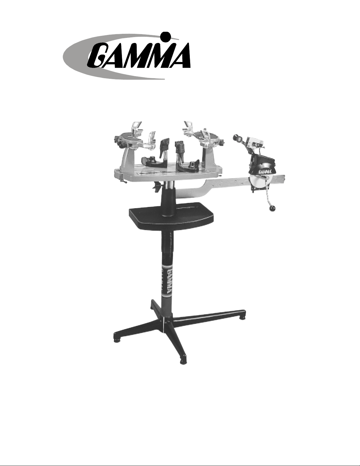
5003
STRINGING MACHINE
OO
WNER'S MANUWNER'S MANU
O
WNER'S MANU
OO
WNER'S MANUWNER'S MANU
Issue 3 - December 14, 2000
Copyright 2000 GAMMA Sports - All Rights Reserved
ALAL
AL
ALAL
Page 2

5003
OWNER’S MANUAL
TABLE OF CONTENTSTABLE OF CONTENTS
TABLE OF CONTENTS
TABLE OF CONTENTSTABLE OF CONTENTS
PAGE 1 ................................................................................................ WARRANTY
PAGE 2 ................................................................................................. FEATURES
PAGE 3 .............................................................................. PACKAGE CONTENTS
PAGE 4 ..................................................................... ASSEMBLY INSTRUCTIONS
PAGE 8........................................................................... MOUNTING THE FRAME
PAGE 9.......................................................................... STRINGING THE FRAME
PAGE 11..............................................................STRING CLAMP ADJUSTMENT
PAGE 12......................................................................... TENSION CALIBRATION
PAGE 13................................................................... DISK BRAKE ADJUSTMENT
PAGE 14 ............................................................ PATHFINDER AWL OPERATION
PAGE 15.............................................................................. TROUBLESHOOTING
PAGE 15............................................................................ CARE AND CLEANING
PAGE 16.................................................................... MOUNTING STAND PARTS
PAGE 17.................................................................................... MACHINE PARTS
PAGE 18....................................................................................... PARTS LISTING
LIMITED WARRANTY
GAMMA SPORTS ("GAMMA") warrants to the original purchaser that the GAMMA 5003 stringing machine ("EQUIPMENT") purchased is free from defects
in materials and workmanship for a period of five (5) years from the date of original purchase for mechanical parts (excluding string clamps), and for a period
of one (1) year from the date of purchase for string clamps. Should any defects develop under normal use within the specified time periods, GAMMA will
at its option, repair or replace the defective EQUIPMENT provided it is returned to GAMMA prepaid at the purchaser's expense. This warranty does not apply
to any damage or defect caused by negligence, abuse, misuse, unauthorized alteration, shipping, handling, or part wear and tear as a result of normal use.
GAMMA's obligation under this warranty is limited to repair or replacement of defective EQUIPMENT, and no one is authorized to promise any other liability.
GAMMA shall in no event be liable for any incidental or consequential damages.
To return defective EQUIPMENT, a return authorization (RA#) must be obtained from a GAMMA customer service representative by calling 1-800-333-0337.
The RA# must be marked on the outside of the shipping carton being returned. All returns must be shipped prepaid by the customer to GAMMA. Please retain
the original shipping carton and packing materials for any future shipments.
1
Page 3
5003
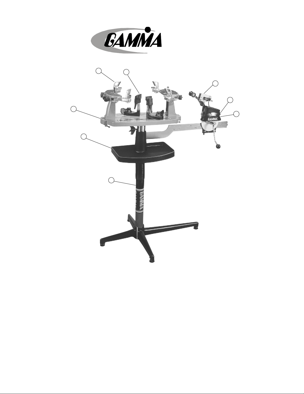
FEATURES
5
6
7
8
1
3
4
2
1- Diamond Coated “Quick Action” Composite String Clamps
2 - Manual Spring Tensioner
3 - Diamond Coated Linear String Gripper
4 - Tension Range: 11lbs. - 89lbs.
5 - 6 Point Mounting System
6 - Full 360 Degree Turntable Rotation
7 - Large Convenient 141 sq. in. Tool Tray
8 - Height Adjustable From 36” to 48”
2
Page 4

5003
P ACKAGE CONTENTS
Y our GAMMA 5003 is shipped in one large carton containing several smaller cartons. Open all cartons and inventory
the parts to be sure that the shipment is complete.
Save the cartons and packing materials for possible future shipments. GAMMA Sports can not be responsible for
machines which are not shipped in original, undamaged packaging.
Carton Contents :
(1) Upper Support Post
(1) Lower Support Post w/ Plate
(1) Long Leg w/ Adjustment Foot
(3) Short Legs w/ Adjustment Feet
(4) M8 x 30 Cap Screws
(4) M8 Washers
(4) M8 x 25 Flat HEad Screws
(1) Bellows Set
(1) Tool Tray w/ Pad
(1) Tensioner Assembly
(1) Tensioner Track
(1) Turntable w/ 2 “Quick Action” Clamp Bases Installed
(2) “Quick Action” Clamp Head Assemblies
(1) Winged Turntable Locking Knob Screw
(2) “Quick Mount” Mounting Stands w/ Side and Slide Support Fitted w/ Plastic Adapters
(2) Mounting Stand Locking Levers w/ Washers
(1) Package of Spare plastic adapters for mounting system (contains 12 pcs)
(1) Spare Tension Calibration Lock Screw
(1) Combination Needle Nose / Cutting Pliers
(1) Straight Stringers Awl
(1) Pathfinder Specialty Awl
(1) 10 pc. Hex Key Set
(1) 10 MM Open End / Box Wrench
(1) 17 MM Open End / Box Wrench
(1) 5 MM “T” Handle Hex Wrench
(1) 4 MM “T” Handle Hex Wrench
3
Page 5
ASSEMBLY INSTRUCTIONS
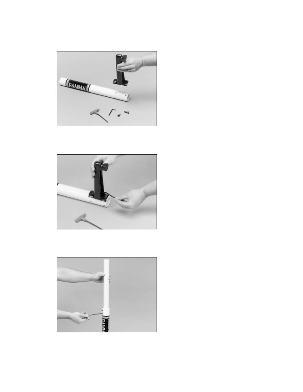
Base Leg Assembly
The GAMMA 5003 stringing machine uses a four leg
base design. The legs must be assembled to the support
post before use. Remove the lower column support from
the carton. This is the larger of the two posts and has the
GAMMA label.
Note: For illustration purposes, the support column has
been painted white for these instructions.
Align the holes in the leg flange with the matching holes
in the lower column support post. Secure the leg with one
FLAT HEAD cap screw through the upper hole, and one
SOCKET HEAD cap screw through the bottom hole.
Repeat this procedure for the three remaining legs.
Base Foot Height Adjustment
Each foot of the GAMMA 5003 Base Stand can be adjusted to compensate for uneven surfaces.
Upper Column Support Assembly
Insert the upper column support into the lower column
support / base leg assembly. Leave the upper column
extended to maximum height and lock in place with the
two set screws located at the top of the lower column
support.
4
Page 6
ASSEMBLY INSTRUCTIONS
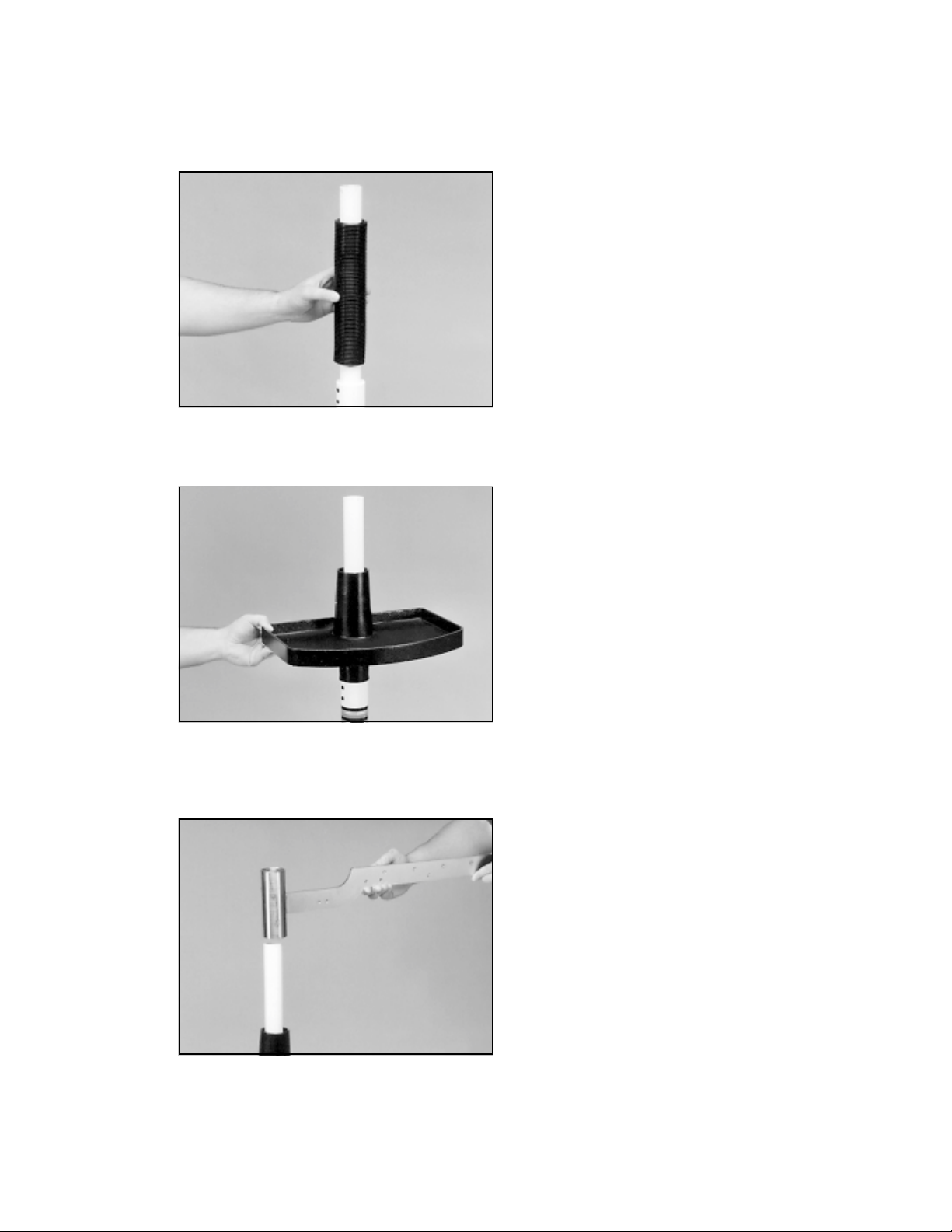
Bellows Installation
The bellows assembly is supplied in two pieces and
should be assembled as follows. Place the bellows
section with the flange over the upper support column
with the flange on the top. Place the remaining bellows
over the upper support column and mate it with the
flange on the lower bellows.
Tool Tray Installation
Lower the tool tray over the top of the upper column
support and let it rest loosely on the bellows assembly.
Tension Track Installation
Place the tube of the tension track assembly over the top
of the upper column support. Securely tighten the two
socket set screws on the tension track assembly tube,
locking it to the upper column support. Align the notch in
the tool tray with the tension track bar while raising the
tool tray. Secure the tray with the set screws in the side
of the tray casting.
5
Page 7

ASSEMBLY INSTRUCTIONS
Installing the Turntable
Insert the center post of the turntable into the bushing
located in the top of the tensioner bar post.
Installing the Frame Support Posts
The GAMMA 5003 support post assemblies are precision aligned at the factory and are marked for proper
installation on the turntable.
Install the support post with the dot on its base to an
identical dot on the turntable. Align the threaded hole in
the bottom of the frame support post with the slot in the
turntable. Screw the lever lock bolt with washer into the
bottom of the support post and tighten gently.Position
the washer with the rounded edge toward the turntable.
Repeat procedure on the opposite side of the turntable.
Locking the Turntable
The turntable may be locked in any position.
The turntable winged lock knob is packed separately in
the accessory polybag. Install the lock knob into the
threaded hole located on the side of the tensioner bar
post.
Rotate the knob clockwise to lock the turntable, and
counter-clockwise to release the turntable.
6
Page 8

ASSEMBLY INSTRUCTIONS
Installing the Tensioner
Remove the button head screw and washer located at
the end of the tensioner bar with the 3 mm hex wrench
provided. Slide the tensioner onto the bar, being careful
to align the bar with all of the bearings and the drive gear
with the gear track. Replace the button head screw and
washer in the end of the tensioner bar.
Setting the Gripper Jaw Spacing
The gripper jaws of the 6004 tensioner are adjustable to
accomodate varying string gauges.
If the string slips through the gripper jaws while pulling
tension, rotate the gripper jaw adjustment screw counterclockwise.
If the string is damaged while pulling tension, rotate the
gripper jaw adjustment screw clockwise.
The jaws will be properly adjusted when there is enough
pressure to securely grip the string without causing
damage to the string.
7
Page 9

MOUNTING THE FRAME
Adjusting the Frame Support Posts
Place the racquet frame over the center posts and onto
the frame support. Loosen the lever lock bolt on one
support post. Slide the post outward until the center
support of the racquet support slide is positioned near
the inside surface of the racquet frame. Securely tighten
the lever lock bolt.
Adjust the opposite post using the same procedure.
Caution: To avoid racquet damage, the center posts
should not contact the racquet prior to fixing the support
posts.
Adjusting the Frame Shoulder Supports
Being sure the shoulder supports are free to swivel in
thier mountings, simultaneously rotate the shoulder
support adjustment knobs clockwise until both shoulder
supports gently and squarely contact the frame.
Tighten the Frame Support Slides at the head and throat
of the racquet until they gently contact the frame between the two center main string grommets.
Securing the Frame
Lock the shoulder supports in position by turning the
knob at the base clockwise.
Repeat the adjustment procedure for the remaining
support post.
Re-tighten all of the frame supports in the same order as
before.
Do not overtighten any of the supports as racquet
damage may occur.
The supports should be tightened to the point where the
racquet frame will not move in the mounting system
when the handle is grasped and attempts are made to
move it. Should any supports lose contact with the frame
while stringing, they should be re-tightened.
8
Page 10

STRINGING THE FRAME
Setting Tension
The GAMMA 5003 utilizes a rotary adjusting knob along
with a linear tension scale to indicate the tension setting.
The scale is divided into 3 lb increments and each 1/3
turn of the tension knob changes tension by 1 lb. To set
the desired tension, rotate the tension knob and align the
mark on the spring guide with the desired tension setting
on the scale. When the “0” mark on the knob aligns with
the line on the knob support the tension will be that
indicated on the scale. To increase tension by 1 or 2 lbs
turn the knob counterclockwise until the “1” or “2” mark
on the knob aligns with the line on the knob support. To
decrease tension by 1 or 2 lbs, turn the knob clockwise
until the “2” or “1” mark on the knob aligns with the line
on the knob support.
Tensioner Travel Stop
To prevent contact between the tension head and the
racquet and/or turntable, a stop screw is located about
midpoint along the tensioner bar below the gear track. In
the event the tension head must be moved closer to the
racquet, turn the stop screw counter-clockwise with the
5 mm hex wrench until the end of the stop screw no
longer protrudes beyond the surface of the tensioner
bar. To re-engage the stop, simply turn the stop screw
clockwise until the screw is seated against the tensioner
bar.
Travel Stop
Clamp Head Operation
GAMMA “Quick Action” Clamps are of a dual action
design where as the clamp head and clamp base
operate independently of one another.
To clamp a string, lift the clamp head and place the string
between the jaws and depress the clamp head lever to
secure the string. The clamping pressure applied to the
string should be adjusted to provide sufficient pressure
to secure the string when subjected to the desired pulling
tension. The diamond coated gripper plates provide for
increased friction between the clamps and the string to
allow for reduced clamping pressure while securing and
holding the string under tension.
9
Page 11

following instructions.
STRINGING THE FRAME
Clamp Base Operation
Rotate the Base Locking Lever clockwise to secure the
clamp base to the turntable.
Reverse the clamping procedure to unlock the string
clamp. The Locking Lever is spring loaded to assist the
unlocking of the clamp base.
The Locking Lever should be tightened enough to prevent clamp base slippage on the turntable, when the
desired tension is placed on the string. To go from the
loose position to the clamped position and back, generally requires the rotation permitted by the slot in th clamp
base. If the rotation is not sufficient to allow smooth
operation of, adjust the Clamp Base Locking Nut as
outlined below.
Note: If the string slips in the string clamp while tensioning,
adjust the gap between the clamp jaws as per the
Clamping the First Main String
To begin stringing the main strings, thread the two ends
of the string through the two center holes at the appropriate end of the frame and continue through the opposite center holes. Thread one end of the string through
the adjacent grommet hole and pull excess by hand.
Secure one of the strings using a string clamp.
Pulling Tension
Wrap the loose section of string once around the roller
guide and insert the string between the diamoind dust
coated string gripper plates. Pull the string perpendicular to the gripper plates while slowly rotating the tensioner
crank clockwise until the brake lever pops out of the
latching block. The string is now tensioned and can be
clamped in place with the remaining fixed clamp.
Repeat the above steps until all main strings are installed. Tie off ends of main strings as per racquet
manufacturers recommendations.
10
Page 12

STRINGING THE FRAME
Weaving the Cross Strings
Weave the cross strings over and under the main strings
being careful to alternate the weave direction of each
consecutive cross string so as to be opposite of the
previously installed cross string.
Once the final cross string is tensioned and clamped, tie
off at the appropriate hole specified by the racquet
manufacturer.
STRING CLAMP ADJUSTMENT
Adjusting the Clamp Jaws
The GAMMA “Quick Action” Clamps will need minor
adjustments according to what string type, construction,
and gauge you are using.
To adjust the gap (clamping pressure) between the
clamp jaws, insert the string through the racquet as if you
were beginning the main strings. Clamp the strings and
pull tension. If the string slips through the jaws of the
Adjustment
Knob
Note: The string clamps supplied with your Gamma stringing machine can accomodate tight string patterns such as
badminton. Depending on the string pattern, the clamp may spread the strings slightly which will not compromise the
quality of the string job.
clamp, tighten the clamp by compressing the clamp
jaws together by hand while turning the Adjustment
Knob, in the clockwise direction. If the clamp leaves
impressions or damages the string, it may be excessively tight and should be adjusted by turning the hex
screw counter clockwise to open the gap between the
jaws. The clamp jaws should be cleaned periodically to
be free from dirt, oil, and any string coating for them to
grip properly.
Adjusting the Clamp Base Locking Nut
In the event the Locking Lever rotation is innsufficient to
ensure smooth operation of the clamp base, very minor
adjustments to the Clamp Base Locking Nut can be
made with the supplied 17mm wrench. Tighten or loosen
the locking nut in very small increments to provide more
clamping pressure or running clearance as needed.
11
Page 13

TENSION CALIBRA TION
Tension Calibration Procedure
Step 1
Set the tension to 60 lbs. as indicated by the linear scale
and rotary knob. Place the string on one end of a tension
calibrator into a string clamp and secure. Place string
located on the other end of the calibrator into the string
tensioner and apply tension. If the brake lever releases
before 60 lbs. or after 60 lbs., the tension head should be
calibrated as follows.
Step 2
Loosen the 1.5 mm locking set screw (A) located on the
side of the latching block as shown. The set screw is
used to hold the adjustment screw in place.
A
Step 3
B
If the lever releases before 60 lbs., using the supplied Lshaped hex wrench, turn the adjustment screw (B)
located on the left side of the latch block counterclockwise to increase the engagement of the brake
release latch with the brake lever. Repeat step 1 and
adjust until the correct tension is indicated on the calibrator.
If the tension indicated in step 1 is greater than 60 lbs.,
turn the adjustment screw clockwise to reduce the
engagement of the brake release latch with the brake
lever. Repeat step 1 and adjust until the correct tension
is indicated on the calibrator.
12
Page 14

DISK BRAKE ADJUSTMENT
A
A - Cover Screws B - Lock Bolt
C
Adjusting the Tensioner Brake
Step 1
A
After stringing many racquets, the brake of the tensioner
may need to be adjusted. The Brake Adjustment Bolt
B
can be accessed through the hole in the face of the
tensioner cover, which does not need to be removed for
adjustment. The Tensioner Cover has been removed in
the pictures for illustration purposes.
Step 2
With the brake lever engaged, loosen the lower hex bolt
located on the back side of the tensioner frame with the
10 mm box wrench. Note: The hex bolt should only be
loosened until loose enough to turned by hand and must
not be removed completely.
C - Brake Adjustment Bolt
Step 3
With the hex bolt loosened and the brake lever engaged
in the latch, insert the 6 mm hex wrench into the set
screw locted inside the nut located at the base of the
brake lever. To tighten the braking mechanism, turn the
set screw counter clockwise by about 1/8 turn. Retighten the hex bolt on the back side of the tensioner
frame and check for brake tightness. The tensioner
should move freely along the track with the brake lever
engaged and should hold tension with the brake lever
released. If more adjustment is needed, repeat steps
above until properly adjusted.
13
Page 15

P A THFINDER A WL OPERA TION
The GAMMA 5003 includes the new Pathfinder stringing
awl which creates a pathway between or around strings
and through tight grommets.
Insert the awl through the grommet hole in the same
manner as for traditional awls. The Pathfinder awl must
be closed before insertion.
Once the awl is inserted, pull the handle of the awl
outward while holding the tip section in place, leaving the
outer sheath in the grommet hole.
Insert the end of the string into the center of the sheath.
While holding pressure on the string, slowly pull the
sheath out of the grommet hole to leave the end of the
string exposed.
14
Page 16

TROUBLESHOOTING TIPS
PROBLEM SOLUTION
String slips in clamps
String slips in gripper
String clamp slips on base - Clean base of clamp and top of turntable
String tension too tight or too loose
For additional assistance, contact Gamma Sports Customer Service at 1-800-333-0337
- Adjust gap between jaws
- Clean clamp jaws
- Clean gripper jaws
- Adjust Gripper Jaw Stop Screw
- Adjust Clamp Base Locking Nut
- Check tension using a tension calibrator and
adjust machine calibration if necessary
CARE and CLEANING
With time and use, the clamping surfaces of your machine may become oily or dirty and result in string or clamp
slippage while stringing. Periodic cleaning of the following parts is recommended.
String Clamps
Clean the inside gripping surfaces of the string clamp jaws by inserting a cloth or pipe cleaner soaked with isopropyl
alcohol between the jaws and rub back and forth. If the build-up is excessive, dismantle the string clamp jaws to
expose the gripping surfaces by removing the adjustment screw. Using a small nylon brush (such as a toothbrush),
a flat sharpening stone, or an ermery board, scrub the inside surfaces until all debris is removed. Clean the jaws
with isopropyl alcohol and re-assemble.
String Clamp Base
Clean the base of the clamps and the top of the turntable with isopropyl alcohol.
String Gripper
Clean inner gripping surfaces with isopropyl acohol soaked cloth or pipe cleaner. In cases where there is a lot of
build-up, use a flat emery board and scrub the surfaces first.
15
Page 17

5003
MOUNTING ST AND PARTS
147
146
13
15
PART #
9
13
14
15
21
22
23
24
140
144
143
14
145
148
DESCRIPTION
WASHER - M8
POST LOCKING LEVER
WASHER - M10
SUPPORT POST
FRAME SUPPORT SLIDE
BADMINTON ADAPTER
TENNIS ADAPTER
SUPPORT SLIDE KNOB
MTNG. STAND TOP PLATE
24
122
21
PART #
141
142
143
144
145
146
147
148
140
141
142
9
SUPPORT ARM - LEFT
SUPPORT ARM - RIGHT
SHOULDER SUPP. LOCK KNOB
SUPP. ARM RETURN SPRING
ARM ADJUSTMENT KNOB
ARM ADJUSTMENT SCREW
22
23
DESCRIPTION
MTNG. STAND PAD
SHOULDER V-CLAMP
16
Page 18

MACHINE P ARTS
174
180
176
178
5003
117
172
114
106
116A
120A
104
105
111
112
119
113
115
6B
121
9
17
Page 19

5003
P ARTS LISTING
PART #
6B
9
104
105
106
111
112
113
114
115
116A
117
119
120A
121
DESCRIPTION
CAP SCREW - M8 X 30
WASHER - M8
TENSIONER ASSEMBLY
RETAINER SCREW
TABLE BRAKE KNOB
TENSIONER TRACK
TOOL TRAY
LONG LEG
SHORT LEG
FLAT HEAD SCREW - M8
LOWER COLUMN SUPP.
TENSIONER COVER
BELLOWS
UPPER COLUMN SUPP.
LEVELING FOOT
PART #
172
174
176
178
180
DESCRIPTION
2020-25 TURNTABLE
QA CLMP TALL w/GLIDE
BAR
QA CLMP BASE TALL
GLIDE BAR SST
COMP. FIXED CLAMP (THIN)
TOOLS AND ACCESSORIES
70
72
73
98
108
109
167
170
196
HEX WRENCH - 5MM
PATHFINDER AWL
STRINGERS AWL
BOX WRENCH - 10MM
UTILITY KNIFE
NEEDLE NOSE PLIERS
10 PC. HEX WRENCH SET
M10 SUPP - POST SCREWS
BOX WRENCH - 17MM
18
 Loading...