

Page 1

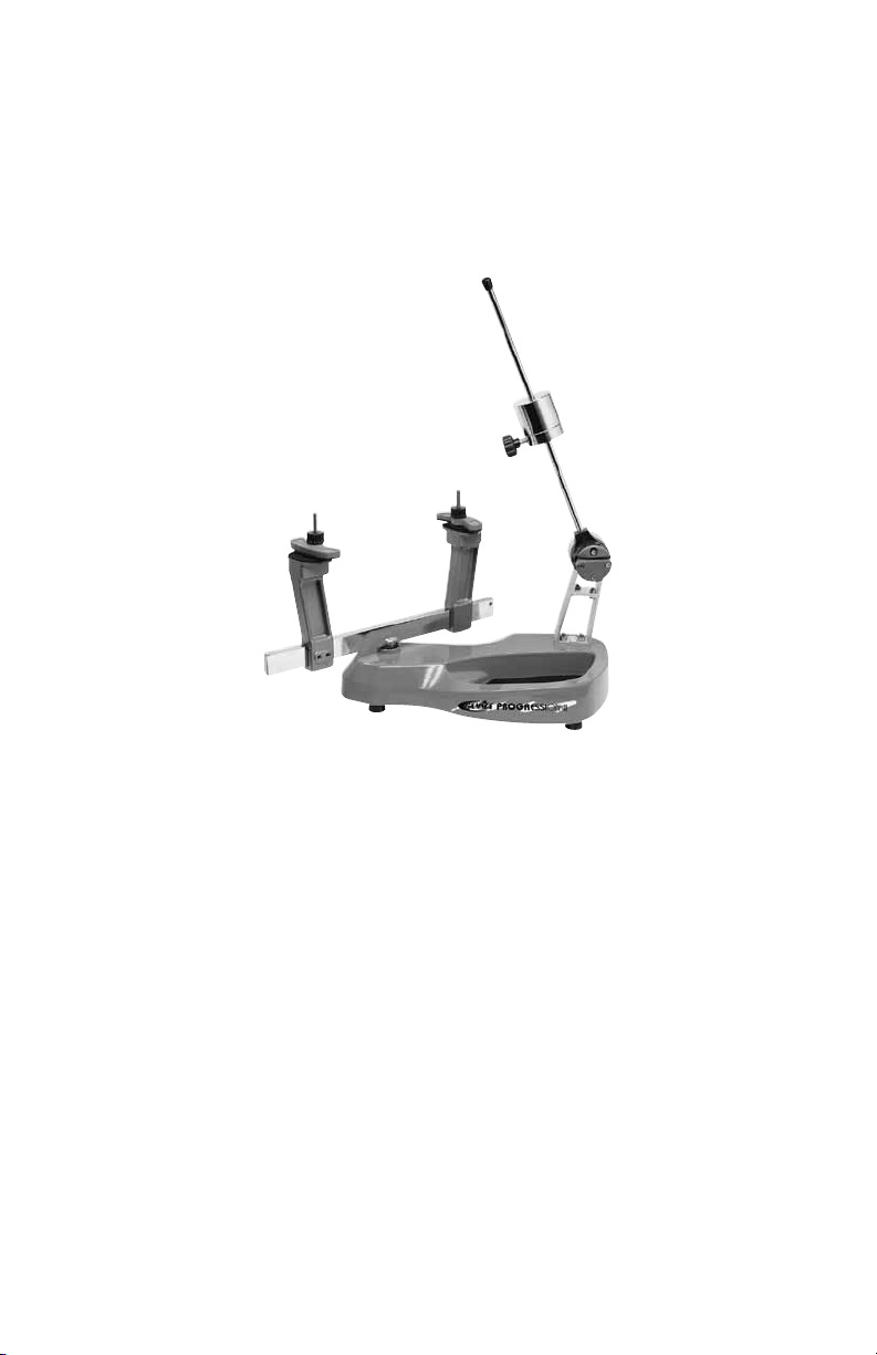
200
STRINGING MACHINE
OWNER’S MANUAL
Issue 1 - July 2010
Page 2

200
OWNER’S MANUAL
WARRANTY ................................................................................................PAGE 2
FEATURES..................................................................................................PAGE 3
ASSEMBLY INSTRUCTIONS .....................................................................PAGE 4
MOUNTING THE FRAME ........................................................................... PAGE 6
STRINGING THE FRAME ...........................................................................PAGE 8
PATHFINDER AWL ....................................................................................PAGE 10
MAINTENANCE & ADJUSTMENT ............................................................ PAGE 11
TROUBLE SHOOTING TIPS ....................................................................PAGE 12
NOTES ...................................................................................................... PAGE 13
PARTS LIST ............................................................................................. PAGE 14
PARTS DRAWING.....................................................................................PAGE 15
LIMITED LIFETIME WARRANTY
GAMMA Sports (GAMMA) warrants to the original purchaser that the Progression 200 stringing machine (“EQUIPMENT”)
purchased is free from defects in materials and workmanship for life of the EQUIPMENT. Should any defects develop under
normal use, GAMMA will at its option, repair or replace the defective EQUIPMENT provided it is returned to GAMMA prepaid
at the purchaser’s expense. This warranty does not apply to any damage or defect caused by negligence, abuse, misuse,
unauthorized alteration, shipping, handling, or part wear and tear as a result of normal use.
Routine maintenance, adjustment, and cleaning required to ensure proper operation are the responsibility of the purchaser
and are not covered under the terms of this warranty. These include, but are not limited to: String Clamp adjustment, as
described on page 4.
GAMMA’s obligation under this warranty is limited to repair or replacement of defective EQUIPMENT, and no one is authorized
to promise any other liability. GAMMA shall in no event be liable for any incidental or consequential damages.
To return defective EQUIPMENT, a return authorization (RA#) must be obtained from a GAMMA customer service representative by calling 800-333-0337. The RA# must be marked on the outside of the shipping carton being returned. All returns
must be shipped prepaid by the customer to GAMMA. Please retain the original shipping carton and packing materials for
any future shipments. GAMMA will not be responsible for machines which are not sent in the original undamaged packaging.
TABLE OF CONTENTS
2
Page 3
FEATURES
MACHINE FEATURES
Drop Weight Tensioner w/ 9 to 90lb range and Permanently
Engraved Weight Scale
Patented Parallel Jaw Rotating Ratchet Gripper w/ Diamond Dust
Coated Gripping Surfaces
Two Point Racquet Mounting System- Accommodates All
Racquets
Two Advanced Composite Floating Clamps w/ Thumb Screw
Adjustment
Durable Polystyrene Base Cover w/ Convenient Padded Tool
Tray
Strong, Light Weight, Powder Coated Molded Aluminum
Construction Tray
3
Page 4
ASSEMBLY INSTRUCTIONS
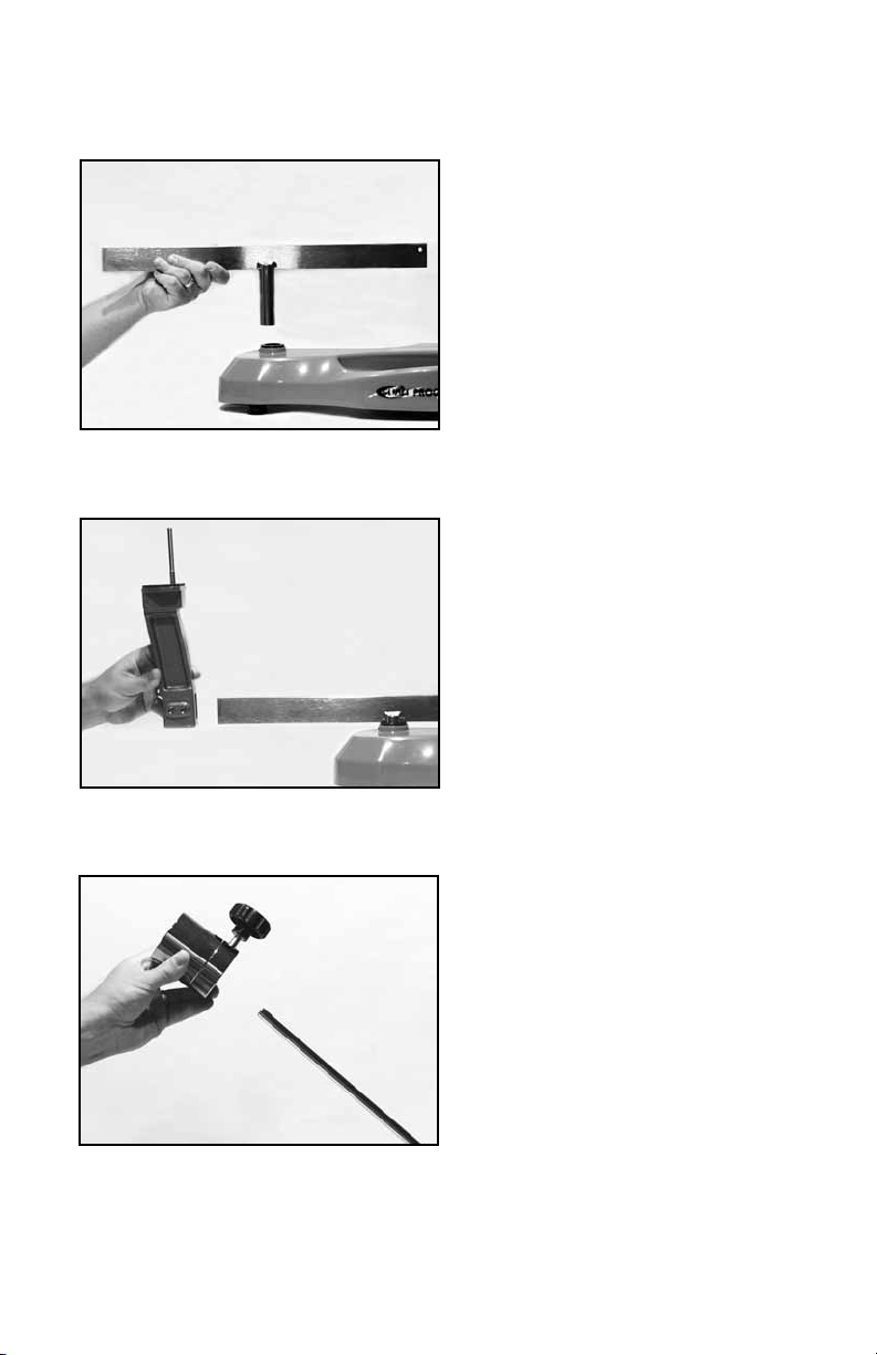
Installing the Turntable
Insert the turntable center post into the bushing assembly of the machine base.
Installing the Support Posts
Slide each support post onto the end of the
turntable bar. The posts should be oriented
so as to angle away from the turntable
center post.
Installing the Drop Weight
Remove the end cap from the tension bar and
slide the drop weight onto the bar. The weight
should be oriented with the knob end closest
to the string winder. Replace the end cap.
4
Page 5

ASSEMBLY INSTRUCTIONS
Tension Bar Stop Screw
Raise the Tension Bar to an upright position.
Using the supplied 5MM wrench, securely
tighten the Stop Screw. This will prevent
the Tension bar from contacting the racquet
frame.
5
Page 6

MOUNTING THE RACQUET
Installing th e R acq uet Support
Adapters
The machine is supplied with two styles of
Racquet Support Adapters. A thick prole
adapter for wide body racquets and a thin
prole adapter for conventional racquet
frames. The Adapters are also tapered, use
the highest side of the adapter that does not
interfere with the string grommet holes.
Adjusting the Frame Support Posts
Place the racquet frame over the center posts
and onto the frame support posts. Loosen the
locking screws on one support post and slide
the post in the appropriate direction until the
plastic adapter contacts the frame. Securely
tighten the locking screws. Adjust the opposite
post in the same manner.
Note: It is extremely important both plastic
adapters are in contact with the frame to
prevent racquet damage.
Securing the Racquet
With the frame support posts properly adjusted, place the frame hold down clamps
over the center screws and tighten the clamp
bar knobs securely. Do not overtighten the
knobs as frame damage may occur.
Note: Inverted throat racquet frames may
require the throat clamp plate to be rotated
180 degrees to match the frame.
6
Page 7

STRINGING THE FRAME
Setting Tension
The drop weight is of a two piece design.
When assembled, it will accommodate tensions from 20 to 90 lbs. For tensions from 8
to 20 lbs., remove the 5mm bolt on the face of
the drop weight, and use the smaller portion
of the weight as described above.
Note: Tensions above 77lbs. require removal
of the drop weight bar end cap.
To set the stringing tension, loosen the
locking knob on the side of the drop weight.
Slide the weight in the appropriate direction
until the face closest to the string gripper is
indexed with the desired tension mark on
the tension bar.
Starting the Main Strings
To begin stringing the main strings, count the
number of holes at the throat of the frame,
which will determine the starting point. For
racquets with 4 or 8 holes at the throat,
the main strings will begin at the head. For
racquets with 2 or 6 holes at the throat, the
main strings will begin at the throat.
Thread the two ends of the string through
the two center grommet holes at the head
or throat as determined in the previous
step. Route the strings through the opposite
center holes.
7
Page 8

STRINGING THE FRAME
Clamping the First Main String
Thread one end of the string through the
adjacent grommet hole and pull excess by
hand. Clamp both the center and the adjacent
string to each other on the inside of the frame.
Pulling Tension
Wrap the free string clockwise around the
gripper drum once and position between
the gripper jaw.
Gently turn the gripper clockwise while
squeezing the jaws together until all slack
in the string is removed.
Note: For proper operation, the string gripper jaw must be in the position shown. The
tension in the string provides the clamping
force to the jaws.
While holding the string gripper drum with
your hand, lift the tension bar to approxmately
45 degree angle and let fall. If the tension
bar drops below horizontal, repeat the above
action until the bar comes to rest parallel to
the racquet. The set tension will be reached
when the bar rests horizontal.
If the bar comes to rest above horizontal,
release the string and re-pull tension.
Manually forcing the bar into the horizontal
position will greatly increase string tension
and may result in racquet damage.
8
Page 9

STRINGING THE FRAME
Clamping the String
Clamp the tensioned string to the next adjacent string using the second string clamp.
Release the tensioned string by raising the
tension arm.
Repeat the procedure for all of the remaining
main strings and tie off following the racquet
manufacturers recommendations.
Starting the Cross Strings
Follow the manufacturer's recommended
stringing pattern for one or two piece stringing. This will determine the starting point for
the cross strings. Weave the rst two cross
strings and pull tension and clamp the cross
strings to each other.
Finishing the String Job
Weave and tension the remaining cross
strings and tie off at the specied grommet
hole.
Remove the strung racquet from the reverse
order of mounting.
9
Page 10
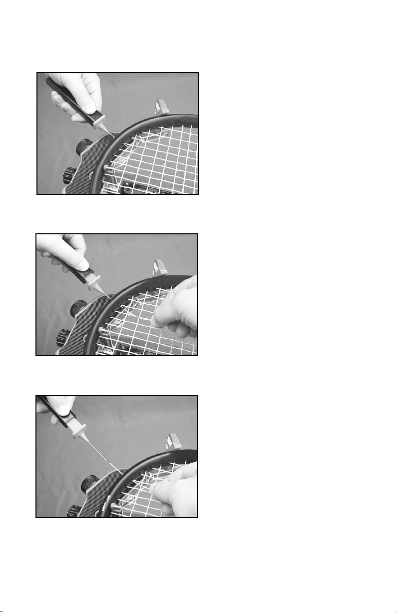
PATHFINDER AWL
The machine includes the pathnder stringing awl which creates a pathway between
or around strings to make inserting a string
through blocked grommets easier and
quicker.
Insert the awl through the grommet hole in
the same manner as for traditional awls. The
Pathnder awl must be in the closed position
before insertion.
Once the awl is inserted, pull the handle of
the awl outward while holding the tip section
in place. This leaves the outer sheath in the
grommet hole. Insert the end of the string
into the outer sheath.
While holding the string, slowly pull the sheath
out of the grommet hole to leave the free end
of the string exposed.
10
Page 11

MAINTENANCE & ADJUSTMENTS
Your stringing machine is adjusted for optimum performance at the factory and needs no
further adjustments before use. After extensive use however, the machine may need minor
adjustments as follows :
Turntable Bushing Adjustment
The turntable bushing is adjusted at the factory for optimum performance. After time and
use, the turntable bushings may need minor
adjustment. An adjustment is indicated when
noticeable turntable looseness or wobble
occurs while stringing.
To adjust the t between the turntable pin
and the bushings, tighten the set screw at the
top of the bushing using a 3mm hex wrench.
Tighten until the turntable rotates smoothly
without excessive free play.
Clamp Adjustment
The oating clamps provided with your machine will need minor adjustments according
to what string type, construction, and gauge
you are using.
If the strings slip through the jaws of the
clamp, tighten the clamp by turning the
thumb knob opposite of the handle, in the
Adjustment
Knob
from dirt, oil, and any string coating for them to grip properly. Keep the clamp jaws clean with
isopropyl alcohol.
clockwise direction. If the clamps leave
impressions or damages the string, they are
too tight and the thumb wheel must be turned
counterclockwise.
The clamp jaws must be clean and free
11
Page 12

TROUBLESHOOTING TIPS
PROBLEM SOLUTION
String slips in clamps - Adjust gap between clamp jaws
- Clean clamp jaws
String slips in gripper - Clean gripper jaws
- Make sure string is wrapped over top gripper
prior to inserting between gripper jaws
With time and use, the clamping surfaces of your machine may become oily or dirty and result
CARE & CLEANING
in string or clamp slippage while stringing. Periodic cleaning of the String Clamps and String
Gripper is recommended. Knife sharpening stones work well for cleaning the diamond coated
string clamping surfaces. Cleaning with a solvent such as isopropyl alcohol and a mild abrasive
tool such as a toothbrush also works well to remove oily or greasy build up.
12
Page 13

NOTES
13
Page 14

PARTS LIST
PART # DESCRIPTION TOOLS & ACCESSORIES
4A TURNTABLE BUSHING
5 RUBBER FOOT
6A CAP SCREW- M8x25
8A SET SCREW- M5x6
24 KNOB
25 TENSION BAR
26 TENSION BAR CAP
27 DROP WEIGHT KNOB
28 FRONT WEIGHT- BADMINTON
29 BACK WEIGHT
30 TENSION BAR DRUM
30A SET SCREW
31 STRING GRIPPER DRUM
47 FLOATING CLAMP KNOB
48 SWING BOLT
49 RETURN SPRING
50 PIVOT PIN
51 RETAINING RING
78 CLAMP PLATE
79 CLAMP PLATE PAD
82 FRAME SUPPORT SHORT
82A FRAME SUPPORT TALL
83A TENSION BAR STOP SCREW
92 TURNTABLE
93 SUPPORT POST
94 SUPPORT POST PIN
95 SUPPORT POST PAD
161 WINDER BEARING
162 GRIPPER PIVOT PIN
163 PIVOT PIN RETAINER COLLAR
257 LOWER WINDER STAND
258 UPPER WINDER STAND
316 BASE
350 BASE COVER
MPFC FLOATING CLAMP
MRSG ROTATIONAL GRIPPER
70 5MM T-HANDLE HEX WRENCH*
98 BOX WRENCH- 10MM*
108 UTILITY KNIFE*
109 NEEDLE NOSE PLIERS*
315 TURNTABLE RAISE RING
MA STRINGER’S AWL*
MPSA PATHFINDER AWL*
* (NOT SHOWN)
OPTIONAL TOOLS & ACCESS
MBFC BADM FLOATING CLAMP
MPMC MACHINE COVER
MPG STARTING CLAMP
MPS CLEANING STONE
SGSM STRINGER'S MAT
14
Page 15

79
94
82
51
24
95
48
82A
78
49
PARTS DRAWING
MPFC
47
25
163
50
83A
258
92
257
161
26
28
27
29
30A
31
30
162
93
8A
4A
315
MRSG
350
316
5
6A
15
Page 16

GAMMA SPORTS
200 Waterfront Drive
Pittsburgh, Pennsylvania 15222
Phone: 800.333.0337 Fax: 412.323.0317
Visit our website at www.gammasports.com
Copyright 2010 GAMMA Sports - All Rights Reserved
 Loading...