

Page 1
INSTALLATION INSTRUCTIONS
Product Revision Form #
14" LOW PROFILE CONSOLE BOX
Rev D
MCS-LOWBOX
The purpose of this instruction sheet is to illustrate the manufacturer's recomended method for installing the 14" Low
Profile Console Box, also known as MCS-LOWBOX. Communication controls are getting smaller in size and there is
no need for unused space in an already compact environment. Included with the 14" Low Profile Console Box are four
sets of short F aceplate Vertical Offsets. These Faceplate Vertical Offsets must be used in place of the Vertical Offsets
that come with Gamber-Johnson Faceplate Kits (see INST3).
INST-274
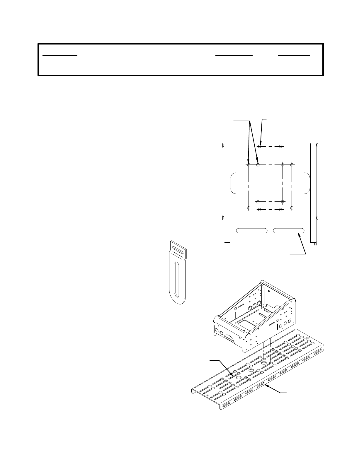
1. When installing the 14" Low Profile Console
Box onto a Gamber-Johnson MCS Top Plate,
insert and loosely assemble four 1/4-20 carriage
bolts, four 1/4" Dia. washers, four 1/4" Dia lock
washers and four 1/4-20 hex nuts about the
specified Gamber-Johson hole-pattern in the
bottom of the box (see FIG. 1). Orient the head
of the carriage bolts below the box.
2. Insert the four heads of the carriage bolts into
the desired corresponding key holes (see FIG. 3)
on the MCS-Top Plate until the bolt heads drop
below the Top Plate. Place box in desired
position and tighten hardware.
3. When installing the 14" Low Profile Console
Box ont o a Dodge Factory Top Plate, insert four
1/4-20 H e x Head Cap Screws into the Top P l at e.
Line up the designated Dodge hole-pattern in the
bottom of the box (seeFIG. 1) with the four
1/4-20 HHCS. Fasten by assembling four 1/4"
Dia. washers, four 1/4" lock washers and four
1/4-20 hex nuts onto the the 1/4-20 HHCS in the
bottom of the box.
4. Due to the decreased depth of this console
box, as compared to the MCS-Epic console box
series, it is necessary to replace the standard
Vertical Offsets with shorter Vertical Offsets (4
sets included with the 14" Low Profile Console
see FIG. 2). Follow instruction sheet INST
Box,
3 for assembly and installation instructions,
substituting the short Faceplate Vertical Offsets
for the Vertical Off-sets that come with
Gambe r-Johnso n Facplate Kits.
5. Finally, install the desired radio control heads
into the box (refer to INST 3). Connect any
wiring necessary and add desired components.
The box comes with mounting slots for a work
lamp, cup holders and AMPS pattern. There are
eleven .88" knockouts provided on the box for
running wires, venti lation, etc.
HOLE-PATTERNS MOUNT
BOX CENTERED TO
HAVIS/DODGE TOP PLATES
FIG. 1
SLOTTED PATTERN MATCHES
FIG. 2
KEYHOLE
HOLE-PATTERN MOUNTS
BOX CENTERED TO
GAMBER-JOHNSON TOP
PLATES 11122 & 11123
MOUNTING PLATFORMS
MANUFACTURED BY
OTHER MOUNT COMPANIES
MCS TOP
PLATE
Product Mounting Disclaimer
Gamber-Johnson is not liable under any theory of contract or tort law for any loss, damage, personal injury, special, incidental or consequential damages for personal injury or other damage
of any nature arising directly or indirectly as a result of the improper installation or use of its products in vehicle or any other application. In order to safely install and use Gamber-Johnson
products full consideration of vehicle occupants, vehicle systems (i.e., the location of fuel lines, brakes lines, electrical, drive train or other systems), air-bags and other safety equipment is
required. Gamber-Johnson specifically disclaims any responsibility for the improper use or installation of its products not consistent with the original vehicle manufactures specifications
and recommendations, Gamber-Johnson product instruction sheets, or workmanship standards as endorsed through the Gamber-Johnson Certified Installer Program.
© copyright 2012 Gamber-Johnson, LLC
FIG. 3
If y ou need assistance or have questions, call Gambe r-Johnson at 1-800-456-6868
Sheet 1 of 2
Page 2
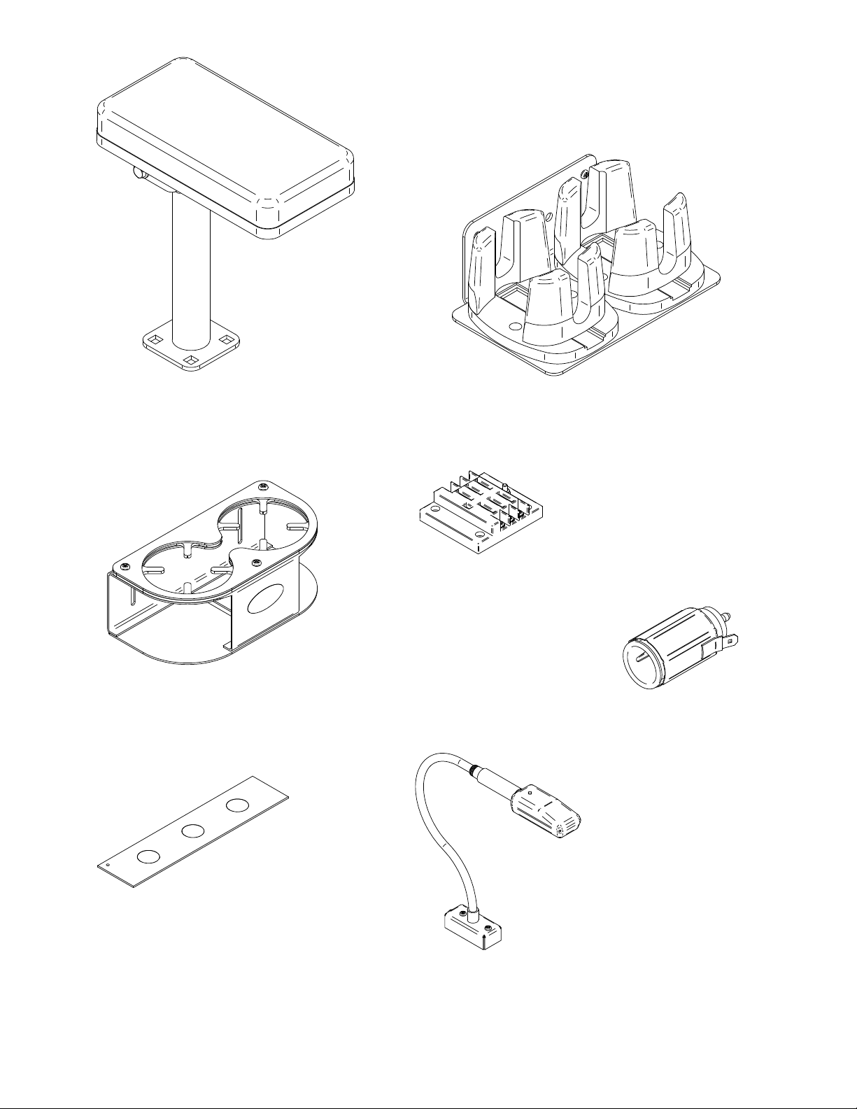
Addition al MCS A c c e ss o r ie sAddition al MCS A c c e ss o r ie s
MCS-ARMREST MCS-CUP2
MCS-CUPHOLD2
3130-0361
(Knockout Filler Panel)
7160-0110
(6 Circuit Power Strip)
7160-0063
(Cigarette Lighter Adapter Kit)
7160-0100
(L ED Light Assembly)
Sheet 2 of 2
Page 3

INSTALLATION INSTRUCTIONS
Product Date Form #
Faceplates 02/23/01 INST3
ASSEMBLING MCS FACEPLATES: (Refer to figure 1)
1. Check that the following pieces are present:
Dual lock fastener (supplied w/console box)
(1) faceplate vertical offset
(1) faceplate top bracket
(1) flat washer #6
(1) 6-32 nut
2. For each faceplate, slide the faceplate vertical offset
(item 1) on the stud in faceplate top bracket (item 2).
Add flat washer (item 3) and hex nut (item 4). Remove
the extra strips of dual lock fastener pressed onto each
console box under holddown rails, cut to same length as
each faceplate, remove protective film covering the
adhesive strip and apply to top bracket as shown.
3. If the faceplates are being mounted in an older style MCS Console Box (those with threaded inserts on the
top surface of the side panels/holddown screws passing through slots in existing face plates or blank
panels), DO NOT attach the strip of dual lock fastener on each faceplate as described above. When
installing faceplates into these MCS Console Boxes, mark any that cover the threaded inserts and drill a .312
diameter clearance hole as shown in Figure 1.
ASSEMBLING MCS FACEPLATES TO CONTROL HEADS AND INSTALLING IN MCS CONSOLE BOXES (Refer to figures
2 & 3).
1. Install the faceplates on each control head as shown in figure 2. Adjust the faceplates so the mounting
holes in the sides of the control head line up in the slots of the faceplate vertical offsets and so the desired
amount of the control head will extend from the console. Make sure to allow enough room underneath for
any connectors that may be required. Test the fit of each control head, the tallest heads may need to be
installed near the higher end of the console.
2. Arrange the control heads in the console box as desired. Blank panels of various sizes have been provided to
act as spacers between each control head, if needed. Secure in place by attaching a piece of dual lock
fastener to each end of the blank panel and then pressing the strips of dual lock fastener on the faceplates,
blank panels and console box together.
3. Attach the MCS Console Box holddowns to the sides of the console box and over faceplates with (6) 10-32 x
.38 Phillips head machine screws.
 Loading...