

Page 1
INSTALLATION INSTRUCTIONS
Product Revision Form #
MCS-ERGOBOX, MCS-ERGOBOX12, & ACCESSORIES
Rev C
UNIVERSAL VERTICAL CONSOLE BOX
The purpose of this instruction sheet is to illustrate the manufacturer's recomended method for installing the
MCS-ERGOBOX.
Includ e d with the
end of the console box, these Faceplate Vertical Offsets must be used in place of the Vertical Offsets that come with
Gamber-Johnson Faceplate Kits (see INST-3).
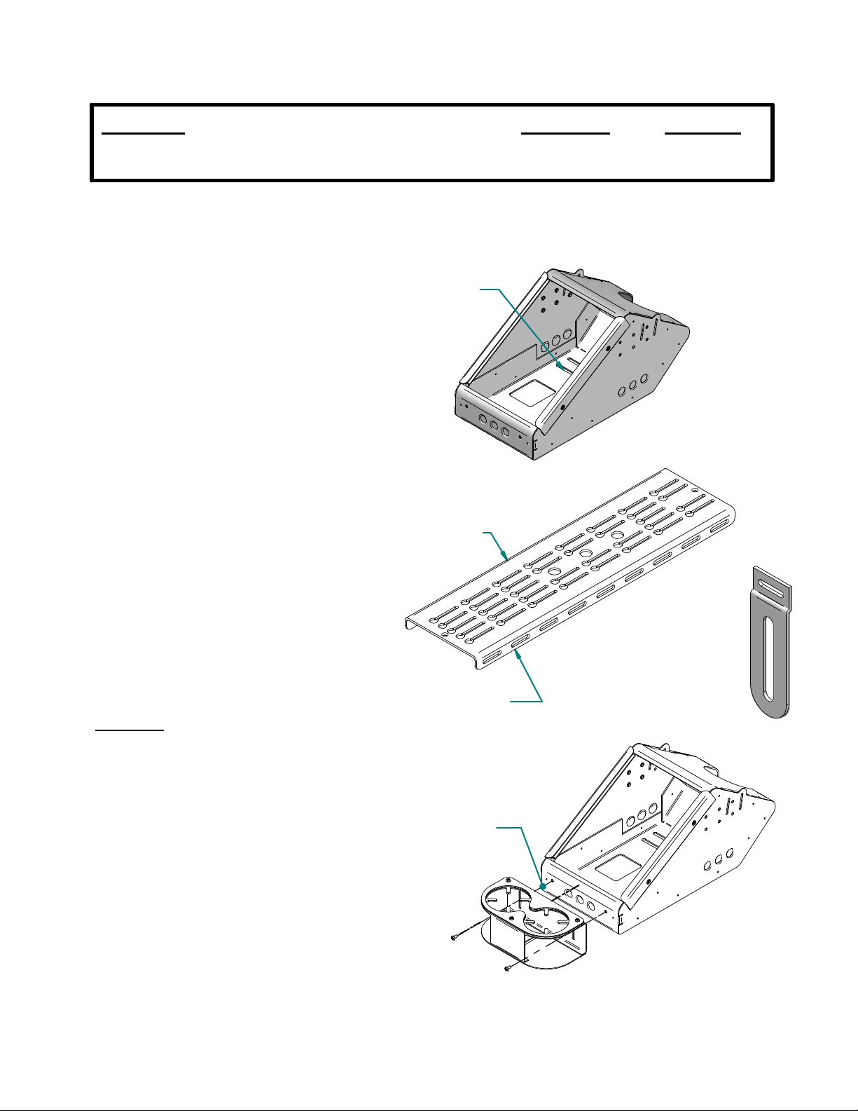
1. When installing the MCS-ERGOBOX onto a
Gambe r-Johnso n MCS Top Plate, insert and loosely
assembl e f our 1/4-20 ca rri age bolts, fo ur 1/4 " Dia.
washers, four 1/4" lock washers and four 1/4-20 hex
nuts about the desired mounting slots in the bottom of
the box (see FIG. 1). Orient the head of the carriage
bolts below the box.
2. Insert the four heads of the carriage bolts into the
desired corresponding key holes (see FIG. 1) o n the
MCS-Top Plate until the bolt heads drop below the
Top Plate. If the chosen mounting slots d o not line
up with the key holes on the Top Plate it will be
necessary to assemble the hardware about the box
and the Top Plate at the same time. Place box in
desired position and tighten hardware.
3. Due to the shallow depth of the face nearest the
vehicl e occupants (see FIG. 3), as compared to the
MCS-Epic console box series, it is necessary to replace
the standard Vertical Offsets with a set of shorter
Vertical Offsets (1 set is included with the
MCS-ERGOBOX). The radio/radio head in the lowest
position on the box will require the Short Vertical
Offset. Follow instruction sheet INST-3 for assembly
and installation instructions, substituting the short
Faceplate Vertical Offsets (s ee FIG. 2) w ith the
Vertical Offsets that come with Gamber-Johnson
Facplate Kits.
ccessories
A
MCS-ERGOBOX is a descrete solution for mounting various mobile communication control heads.
MCS-ERGOBOX is one set of short Faceplate Vertical Offsets. Due to a shallow depth in the front
MOUNTING
SLOTS
FIG. 1
KEY HOLES
MCS TOP PLATE
INST-284
FIG. 2
The MCS-ERGOBOX has many accessories that are designed to attach to the
exterior of the box. The next few sections of this instruction sheet are dedicated to
illustrating how to attach the various accessories.
Cup Holder (MCS-CUP2)
1. The cup holder is designed to mount to either
the short, front face of the MCS-ERGOBOX or
directly to an MCS Top Plate. There are two
10-32 x .375 Phillips Pan Head screws included
to attach the cup holder to the box (see FIG. 3)
Product Mounting Disclaimer
Gamber-Johnson is not liable under any theory of contract or tort law for any loss, damage, personal injury, special, incidental or consequential damages for personal injury or other damage
of any nature arising directly or indirectly as a result of the improper installation or use of its products in vehicle or any other application. In order to safely install and use Gamber-Johnson
products full consideration of vehicle occupants, vehicle systems (i.e., the location of fuel lines, brakes lines, electrical, drive train or other systems), air-bags and other safety equipment is
required. Gamber-Johnson specifically disclaims any responsibility for the improper use or installation of its products not consistent with the original vehicle manufactures specifications
and recommendations, Gamber-Johnson product instruction sheets, or workmanship standards as endorsed through the Gamber-Johnson Certified Installer Program.
© copyright 2009 Gamber-Johnson, LLC
FRONT FACE
FIG. 3
If y ou need assistance or have questions, call Gambe r-Johnson at 1-800-456-6868
SHEET 1 OF 3
Page 2
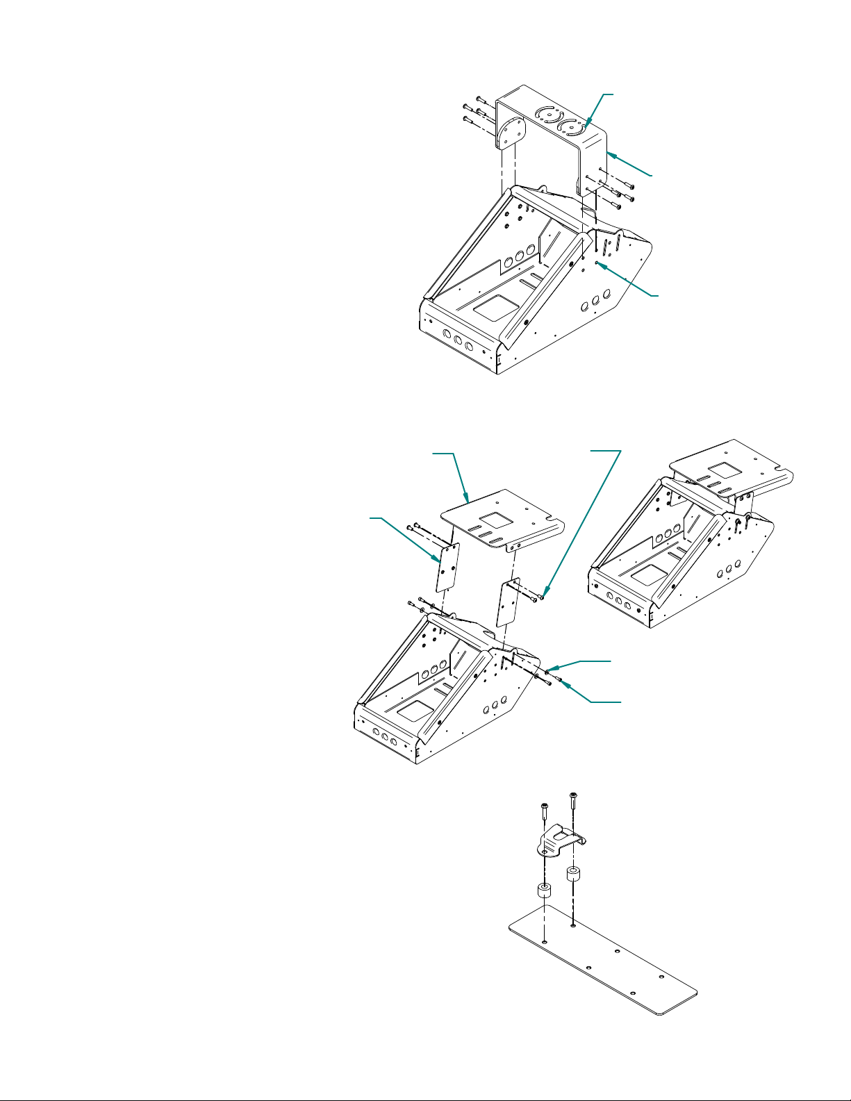
Com munications Bracket (MCS-COMBRKT)
1. The communications bracket is designed to
have any Gamber Johnson Clevis device
mounted to it. In order to mount a
Clevis/Docking Station, or Computer Cradle,
assembly to the MCS-COMBRKT, the
MCS-ERGOBOX must be pulled away from the
dash. Assemble the MCS-COMBRKT, desired
Clevis Device, and MCS-ERGOBOX proir to
attaching the box to the Top Plate (see FIG. 4).
2. Adjust the assembly to the desired position.
Attach to Top Plate by assembling four 1/4-20
carriage bolts, four 1/4" DIA. flat washers, four
1/4" lock washers and four 1/4-20 hex nuts about
the bottom of the box and the Top Plate.
NOTE: The pattern of mounting holes for the
MCS -COM B RKT is k nown as an AMPS pattern.
SMILEY FACE PATTERN FOR
MOUNTING CLEVIS DEVICE
MCS-COMBRKT
AMPS PATTERN
FIG. 4
Mounting to the In-Dash Bracket
1. If mounting the MCS-VERTBOX12 in
a Ford Crown Victoria, the b ox can also
attach to the In-Dash Bracket for further
stability, using NP-DASH-KT (see FIG.
5).
2. After the In-Dash Bracket is attached
to the vehicle, align the MCS-ERGOBOX
and fasten to the In-Dash Bracket using
two braces, four 1/4-20 x .50" Socket
Button Head screws, four 10-32 x .50"
Socket Head C a p Screws an d four #10
flat washers all found in NP-DASH-KT.
Assemble as illustrated in FIG. 5.
Assembling the MCS-MICPLT
1. The MCS-MICPLT is a kit that allows a
radio microphone to be mounted in the same
fashion as all Gamber Johnson Faceplates.
The mic clip itself is not provided with the
MCS -MICPLT kit as it is standard that a mic
clip is shipped with most communication
devices that use a microphone. Assemble as
illustrated in FIG. 6.
BRACE
IN-DASH
BRACKET
1/4-20 X .50"
#10 WASHER
10-32 X .50"
FIG. 5
2. It is recommended that if using the
MCS-MICPLT kit to place the finished
assembly in the lowest position on the
MCS-ERGOBOX. By assembling the kit in
this fashion you be able to avoid using the
short Faceplate Vertical Offset (see FIG. 2).
FIG. 6
SHEET 2 OF 3
Page 3

Addition al MCS A c c e ss o r ie s
MCS-ARMREST
MCS-CUPHOLD2
MCS-CUP2
7160-0110
(6 Circuit Power Strip)
7160-0063
(Cigarette Lighter Adapter Kit)
3130-0361
(Knockout Filler Panel)
7160-0100
(L ED Light Assembly)
SHEET 3 OF 3
Page 4

INSTALLATION INSTRUCTIONS
Product Date Form #
Faceplates 02/23/01 INST3
ASSEMBLING MCS FACEPLATES: (Refer to figure 1)
1. Check that the following pieces are present:
Dual lock fastener (supplied w/console box)
(1) faceplate vertical offset
(1) faceplate top bracket
(1) flat washer #6
(1) 6-32 nut
2. For each faceplate, slide the faceplate vertical offset
(item 1) on the stud in faceplate top bracket (item 2).
Add flat washer (item 3) and hex nut (item 4). Remove
the extra strips of dual lock fastener pressed onto each
console box under holddown rails, cut to same length as
each faceplate, remove protective film covering the
adhesive strip and apply to top bracket as shown.
3. If the faceplates are being mounted in an older style MCS Console Box (those with threaded inserts on the
top surface of the side panels/holddown screws passing through slots in existing face plates or blank
panels), DO NOT attach the strip of dual lock fastener on each faceplate as described above. When
installing faceplates into these MCS Console Boxes, mark any that cover the threaded inserts and drill a .312
diameter clearance hole as shown in Figure 1.
ASSEMBLING MCS FACEPLATES TO CONTROL HEADS AND INSTALLING IN MCS CONSOLE BOXES (Refer to figures
2 & 3).
1. Install the faceplates on each control head as shown in figure 2. Adjust the faceplates so the mounting
holes in the sides of the control head line up in the slots of the faceplate vertical offsets and so the desired
amount of the control head will extend from the console. Make sure to allow enough room underneath for
any connectors that may be required. Test the fit of each control head, the tallest heads may need to be
installed near the higher end of the console.
2. Arrange the control heads in the console box as desired. Blank panels of various sizes have been provided to
act as spacers between each control head, if needed. Secure in place by attaching a piece of dual lock
fastener to each end of the blank panel and then pressing the strips of dual lock fastener on the faceplates,
blank panels and console box together.
3. Attach the MCS Console Box holddowns to the sides of the console box and over faceplates with (6) 10-32 x
.38 Phillips head machine screws.
 Loading...