

Page 1
INSTALLATION INSTRUCTIONS
Product Date Form #
Trunk Mounted Shelf for
Rev. B
Ford Crown Victoria/Police Interceptor
MCS-1TMRS-CV & MCS-2TMRS-CV
These instructions describe installing a single shelf, trunk mounted radio shelf assembly
(MCS-1 TMRS-CV), or a double shelf, trunk mounted radio shelf assembly (MCS-2 TMRS-CV).
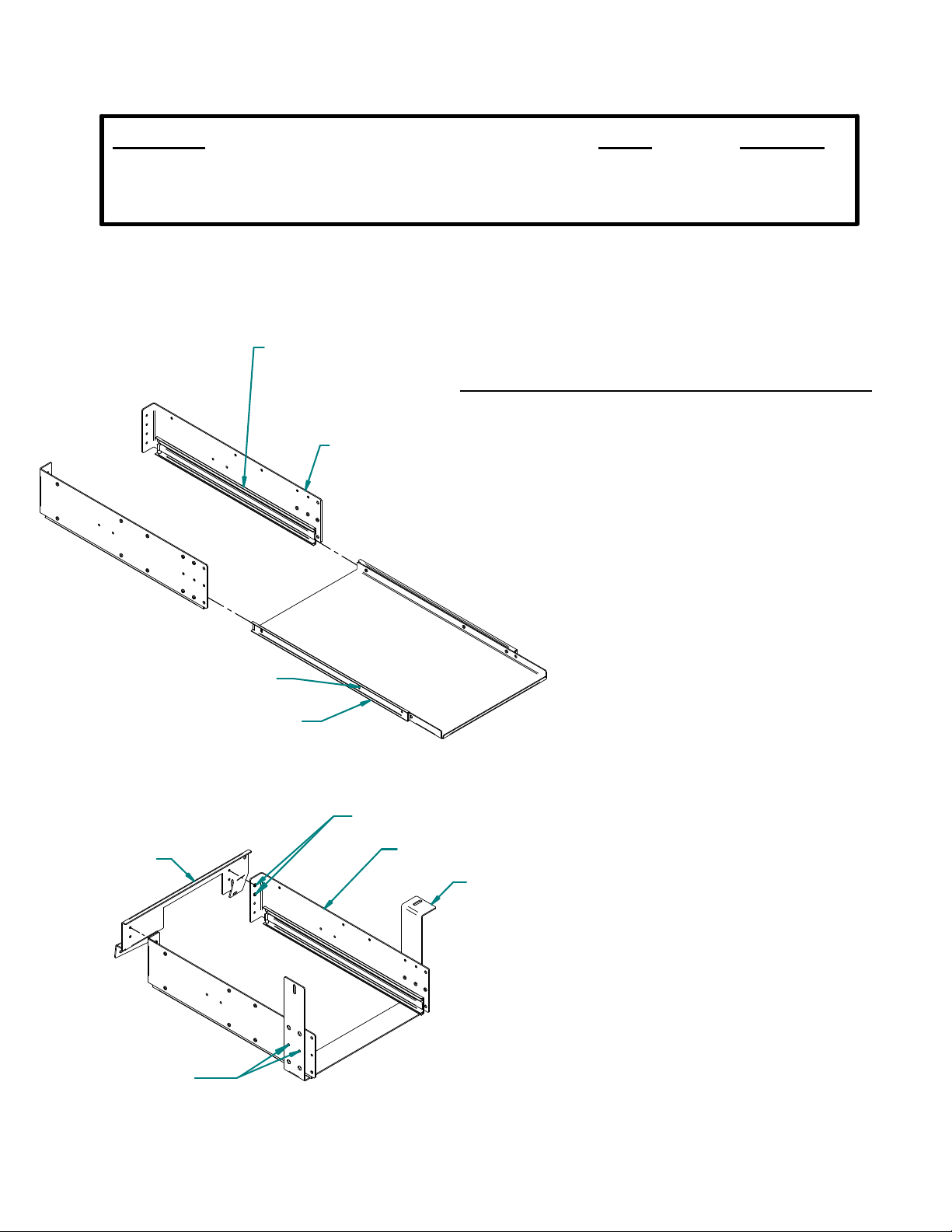
SIDE BRACKETS WITH OUTER HALF
OF SLIDE ATTACHED
nstalling Shelf Assembly on Left Side of Trunk
I
Fig. 1 - Each unit is shipped with the inner half of the
SIDE BRACKET
slide attached to the shelf and outer half of the slide
attached to the side brackets.
INST-44
FIG. 1
BACK BRACKET
FIG. 2
RELEASE LATCH
SHELF WITH INNER HALF
OF SLIDE ATTACHED
8-32 x .38 SCREWS
SIDE BRACKET
FRONT BRACKET
Fig. 2 - Attach each of the side brackets to
the front bracket with two 8-32 x .38 long
phillips screws and to the back bracket
with two 8-32 x .38 long phillips screws.
8-32 x .38 SCREWS
Product Mounting Disclaimer
Gamber-Johnson is not liable under any theory of contract or tort law for any loss, damage, personal injury, special, incidental or consequential damages for personal injury or other damage
of any nature arising directly or indirectly as a result of the improper installation or use of its products in vehicle or any other application. In order to safely install and use Gamber-Johnson
products full consideration of vehicle occupants, vehicle systems (i.e., the location of fuel lines, brakes lines, electrical, drive train or other systems), air-bags and other safety equipment is
required. Gamber-Johnson specifically disclaims any responsibility for the improper use or installation of its products not consistent with the original vehicle manufactures specifications
and recommendations, Gamber-Johnson product instruction sheets, or workmanship standards as endorsed through the Gamber-Johnson Certified Installer Program.
If y ou need assistance or have questions, call Gambe r-Johnson at 1-800-456-6868
SH 1 OF 4
Page 2
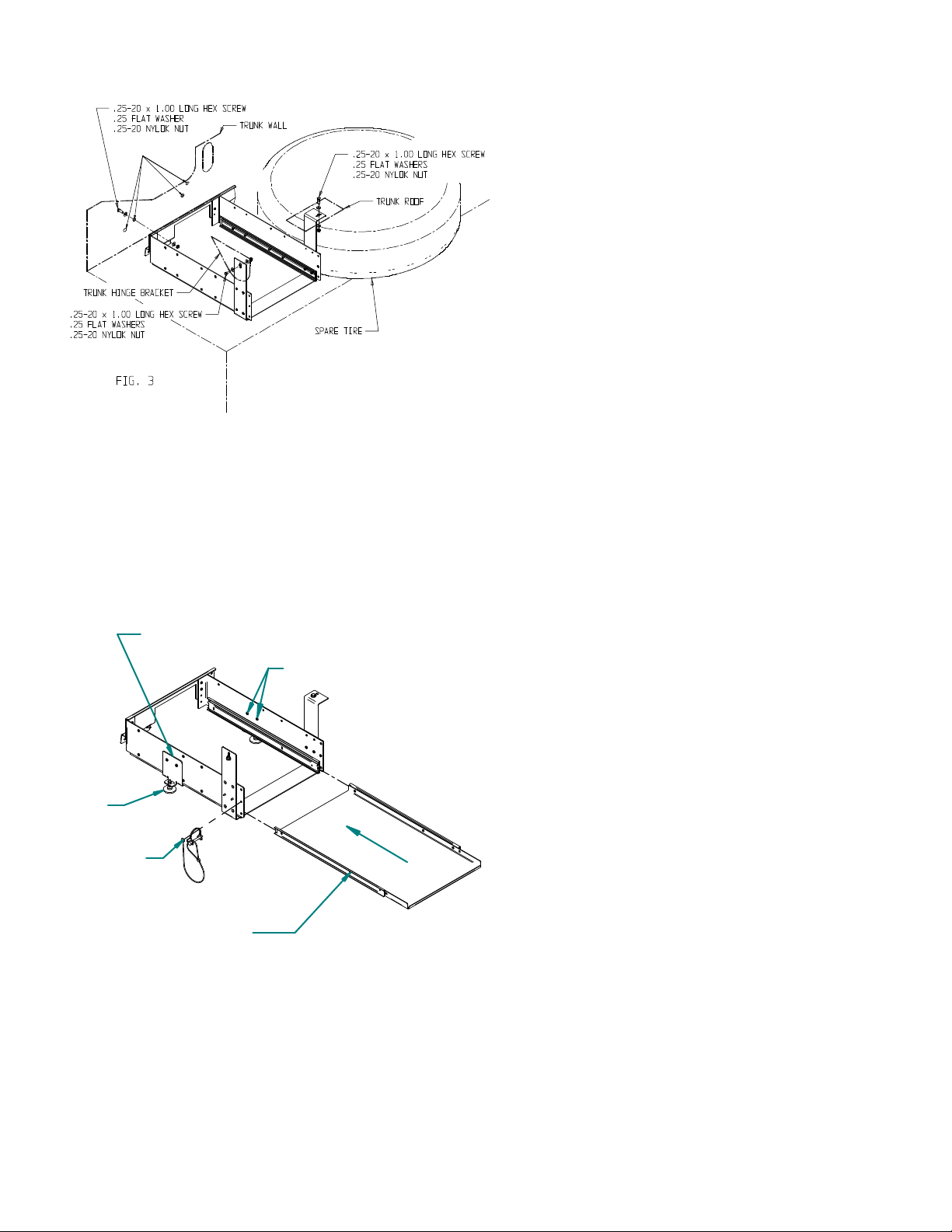
4 PLACES
SUPPORT BRACKET
10-32 x .38 SCREWS
Fig. 3 - Place the assembled shelf
bracket inside the trunk, on the
left side of the spare tire.
Using the existing holes in the
vehicle body.
Loosely attach the back bracket
to the trunk wall and the front
bracket to the trunk hinge bracket
and the trunk roof, with one
.25-20 x 1.00 long hex head
screw, two .25 flat washers and
one .25-20 nylok nut in each of
the places shown.
Fig. 4 - Slide the shelf straight
into the slides.
If needed, each shelf can be removed
by pushing the release latches on
each side and pulling the shelf out of
the slides.
Each shelf can be turned
up-side-down when installing to gain
extra height if needed.
LEVELER &
JAM NUT
8-32 X .38 SCREW
SAFETY SNAP PIN
LANYARD
FIG. 4
RELEASE LATCHES
With the shelf in position tighten down
all nuts and screws attaching the
shelf assembly to the vehicle.
Attach the safety snap pin and
lanyard to the side bracket with one
8-32 x .38 long phillips screw.
Install a shelf support bracket to each
side of the shelf assembly with two
10-32 x .38 phillips screw installed
from the inside surface.
Using a 9/16" wrench turn the
levelers down against the trunk
surface until snug and the weight of
the trunk shelf assembly is supported
by the levelers. Tighten the jam nuts.
SH 2 OF 4
Page 3

Installing Shelf Assembly on Right Side of Trunk
Fig. 5 - Assembly
of shelf is the same
as described in
figures 1 & 2,
except place front
bracket with bent
leg toward center
of vehicle.
FIG. 5
FRONT BRACKET
BENT LEG TOWARD
CENTER
DRILL 5/16" HOLE THRU
TRUNK ROOF AT THIS POINT
DRILL 5/16" HOLE THRU
TRUNK WALL AT THIS POINT
ATTACH TO TRUNK
HINGE BRACKET
ATTACH TO .25-20 x 1.00 SCREW
MOUNTED IN EXISTING
HOLE IN TRUNK WALL
Remove & relocate the spare tire.
Insert one .25-20 x 1.00 long hex head screw thru existing hole in trunk wall. Install one .25-20
hex nut onto screw from trunk side and tighten in place forming a stud.
Place the assembled shelf bracket inside the trunk.
Position the obround hole in the upper right corner of the back bracket ont o the screw just
installed, hold in place with .25 flat washers and .25-20 nylok nut.
Attach the front bracket to the trunk hinge bracket with one .25-20 x 1.00 hex head screw, two .25
flat washers and one .25-20 nylok nut.
Hold the shelf assembly in a level position and mark the location of the obround hole in the front
bracket on the trunk roof and the location of the obround hole in the back bracket on the trunk
wall.
Drill two 5/16" dia holes at points marked.
Insert one .25-20 x 1.00 long hex head screw thru hole drilled in trunk wall and add one .25-20
hex nut from trunk side forming stud as decribed above. Hold back bracket in place with two
.25-20 flat washers and one .25-20 nylok nut.
Insert one .25-20 x 1.00 long hex head screw thru hole drilled in trunk roof and attach the front
bracket with .25-20 flat washer and .25-20 nylok nut.
SH 3 OF 4
Page 4

FIG. 6
8-32 x .38 SCREW
SAFETY SNAP PIN
LANYARD
10-32 x .38 SCREWS
SUPPORT BRACKET
LEVELER &
JAM NUT
Fig. 6 - Slide the shelf straight into the slides.
With the shelf in position tighten down the nuts and screws attaching the
shelf assembly to the vehicle.
Attach the safety snap pin and lanyard to the side bracket with one 8-32 x
.38 long phillips screw.
Install a shelf support bracket to each side of the shelf assembly with two
10-32 x .38 phillips screw installed from the inside surface.
Using a 9/16" wrench turn the levelers down against the trunk surface until
snug and the weight of the trunk shelf assembly is supported by the
levelers. Tighten the jam nuts.
SH 4 OF 4
 Loading...