

Page 1
INSTALLATION INSTRUCTIONS
Product Date Form #
Universal Keyboard Mount
KEYBOARD3
The KEYBOARD3 is a universal keyboard mount that can be adjusted to hold just about any
size keyboard.
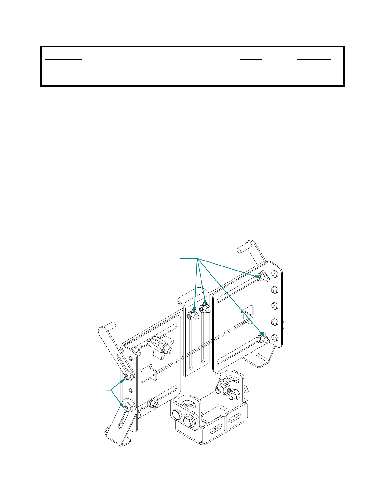
Adjusting the keyboard tray:
1. Loosen the four #10-32unf ny-lok nuts listed below, and the four #8-32unc socket head
cap screws that attach the hold-down clips. DO NOT REMOVE THE HARDWARE.
INST-1941-9-06
#8-32unc socket
head cap screws
#10-32unf ny-lok nuts
If you need assistance or have questions, call Gamber-Johnson at 1-800-456-6868
Page 2
2. Place the keyboard on the tray. Pull the sides apart (extending the spring) until the
keyboard lays flat on the keyboard tray.
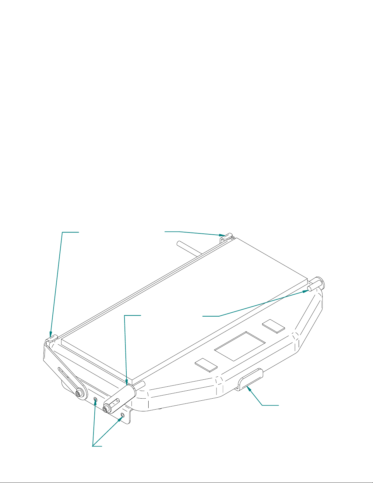
3. Positition the hold-down brackets as shown below. The rear hold-down brackets have a
double function. They hold the rear of the keyboard down on the tray, and also act as a
backstop.
4. Position the keyboard on the tray in the desired location and tighten the two #10-32unf
ny-lok nuts (two of the nuts loosened in step 1) that attach the front stop to the keyboard tray.
5. Position the rear hold-down brackets so they are lightly touching the top and back of the
keyboard. Tighten the brackets in place.
6. Position the front hold-down brackets so the rubber coated pins are lightly touching the
top of the keyboard. Tighten the brackets in place.
7. Position the right side of the keyboard mount to give you enough room to clear the
hold-down brackets with the spring loaded left side. Tighten the two remaining #10-32unf
ny-lok nuts (from step 1) that attach the right side in place.
Rear Hold-down brackets
Front Hold-down
brackets
Front Stop
Optional holes for mounting
hold-down brackets
Page 3

Attaching the keyboard mount to the mounting surface:
1. The keyboard mount has a tilt/mounting bracket that allows for mounting the support on
any flat surface ranging from horizontal to vertical. Attach the tilt/mounting bracket using
1/4-20unc hex bolts, washers, and nuts that were provided in hardware bag 7120-0232.
NOTE: The bolt provided may be to long or short for your application. Should that
condition occur please substitute an appropriate length which can be purchased at any
hardware store.
Mounting flange for
vertical to 45
v
mounting surfaces
Mounting flange for
horizontal to 45
v
mounting surfaces
Installing the Keyboard and Checking the Fit:
The keyboard, when installed in the mount, is retained by spring tension applied to the
left-hand side hold-down clips and the optional three wing safety knob that can be used to
lock the left-hand side in place. The keyboard is installed in the mount by sliding the
keyboard between the front stop and left hand hold-down clips. Push the keyboard to the left
to extend the sping. When the keyboard has cleared the right-hand side hold-down clips,
lower the keyboard onto the tray. The spring load should slide the keyboard under the
right-hand hold-down clips to secure the keyboard. The optional three wing safety knob can
be turned to tighten the left-hand side in place and reduce the possibility of the keyboard
accidentally being knocked out of the mount.
Removal of the keyboard is accomplished by loosening the three wing safety knob and
pulling the right-hand side of the keyboard to the left until it is free of the right-hand
hold-down clips. When it is free, pull the right-hand side of the keyboard up and away from
the mount.
Re-adjust the hold-down clips if necessary to allow the keyboard to easily slide in and out of
the mount.
Page 4

ITEM QTY PART NO. DESCRIPTION
1 1 11722 PLATE, KEYBOARD3 MOUNTING
2 6 4130-0003 WASHER, NYLON, BLACK, .382 ID. X .75OD X .066
3 1 10560 BRACKET, KEYBOARD2 RH CLEVIS
4 1 10559 BRACKET, KEYBOARD2 LH CLEVIS
5 4 3130-0027 .25 FLAT WASHER BLZN
6 4 1173-1412 .25-20UNC X .75 HEX HD CAP SCR
7 2 1503-1400 .25-20 NYLOK NUT
8 2 1403-1400 .25-20 HEX NUT
9 4 4130-0024 WASHER, PLASTIC, 1.00 OD X .28 ID X .06
10 2 11723 SIDE EXTENSION
11 3 4130-0033 MOLDED NYLON INSULATOR
12 5 3130-0579 #10 FLAT WASHER
13 8 1503-1000 NYLOK NUT, 10-32, BLZN
14 1 11724 KEYBOARD SUPPORT, FRONT PLATE
15 1 2400-0005 EXTENSION SPRING
16 1 8700-0010 LABEL, COMPANY
17 1 INST-194 INSTRUCTION SHEET (KEYBOARD3)
18 1 7120-0232 HARDWARE BAG
19 1 11725 LH REAR HOLD-DOWN
20 1 11726 RH REAR HOLD-DOWN
21 2 11727 HOLD-DOWN CLIP
22 2 11314 .125 ID X .625 VINYL CAP
23 4 3130-0008 #8 FLAT WASHER
24 1 11289 10-32UNF 3 ARM KNOB WITH THROUGH HOLE
25 1 4130-0001 .437 OD X .200 ID X .062 - NYLON WASHER
26 4 1183-0806 #8 -32 X .38 SOCKET HD CAP SCR BLZN
27 1 12079-0004 #10 TYPE A EXTERNAL TOOTH LOCK WASHER
19
26
21
22
11
23
13
25
14
24
22
1
21
9
6
15
12
5
13
5
10
4
2
5
3
7
8
20
24
 Loading...