

Page 1
INSTALLATION INSTRUCTIONS
Product Revision
7160-0500, 7160-0502, & 7160-0514
6" LOCKING SLIDE ARM
Rev.B
Printing Spec:
Form
INST-602
PS-001
WARNING
•You must read and follow all of these installation instructions. Failure to follow all of
these installation instructions may result in serious bodily injury or death.
•Do not install or use this product in the area in which the airbag on the vehicle will be
deployed if it is activated. The installer and user of this product is responsible for
installing and using it outside the area in which an airbag will be deployed if
activated. (See Product Mounting Disclaimer Below)
•Keep these installation instructions with the product and readily available in the
vehicle for future reference of other users of the product.
•Additional copies of the installation instructions can be obtained from GamberJohnson. If you need assistance or have any questions, call Gamber-Johnson at
1-800-456-6868.
Installation:
The 6" Locking Slide Arm mounts directly to a Center Upper Pole or other type of
mounting equipment that contains a Gamber-Johnson swivel pattern cutout.
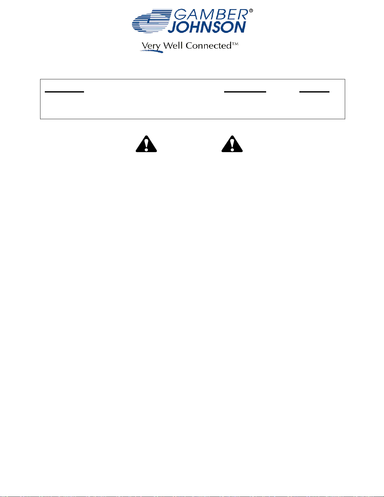
To mount on a Center Upper Pole or other type of mounting equipment that contains
a Gamber-Johnson swivel pattern cutout, set the arm on the mount so the 1/4-20unc
studs protrude through the curved cutouts. Two studs should protrude through one of
the cutouts and one stud should protrude through the opposite cutout. Attach with
the flat washers and lock nuts that are supplied. (See Figure 1.)
Product Mounting Disclaimer
Product Mounting Disclaimer
Gamber-Johnson is not liable under any theory of contract or tort law for any loss, damage, personal injury, special, incidental or consequential damages for personal injury or other damage
Gamber-Johnson is not liable under any theory of contract or tort law for any loss, damage, personal injury, special, incidental or consequential damages for personal injury or other damage
of any nature arising directly or indirectly as a result of the improper installation or use of its products in vehicle or any other application. In order to safely install and use Gamber-Johnson
of any nature arising directly or indirectly as a result of the improper installation or use of its products in vehicle or any other application. In order to safely install and use Gamber-Johnson
products full consideration of vehicle occupants, vehicle systems (i.e., the location of fuel lines, brakes lines, electrical, drive train or other systems), air-bags and other safety equipment is
products full consideration of vehicle occupants, vehicle systems (i.e., the location of fuel lines, brakes lines, electrical, drive train or other systems), air-bags and other safety equipment is
required. Gamber-Johnson specifically disclaims any responsibility for the improper use or installation of its products not consistent with the original vehicle manufactures specifications
required. Gamber-Johnson specifically disclaims any responsibility for the improper use or installation of its products not consistent with the original vehicle manufactures specifications
and recommendations, Gamber-Johnson product instruction sheets, or workmanship standards as endorsed through the Gamber-Johnson Certified Installer Program.
and recommendations, Gamber-Johnson product instruction sheets, or workmanship standards as endorsed through the Gamber-Johnson Certified Installer Program.
© Copyright 2012 Gamber-Johnson, LLC
If you need assistance or have questions, call Gamber-Johnson at 1-800-456-6868
1/3
Page 2
1/4-20UNC STUDS
1/4" BOLTS AND
CENTER UPPER TOP
1/4" FLAT WASHERS
AND NYLOK NUTS
FLAT WASHERS
Figure 1.
CENTER UPPER BOTTOM
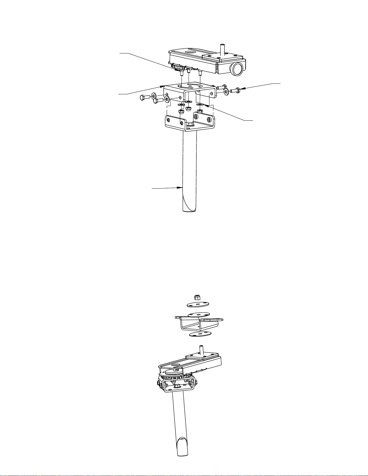
Attaching an Angled Low Swivel to the 6" Locking Arm
To attach an Angled Low Swivel, remove the Nylok Nut, Steel Bearing Backup Plate, the
Top Nylon Bearing, and the supplied 0-90° Clevis from the assembly. Place the Angled Low Swivel
onto the 3/8" stud so it rests on the Bottom Nylon Bearing. Attach the Angled Low Swivel in place
with the Top Nylon Bearing, Steel Bearing Backup Plate, and the Nylock Nut that were removed
when you first removed the bearings from the original clevis configuration. Tighten the Nylok Nut
until the desired friction is obtained for the rotation of the Angled Low Swivel. (See Figure 2)
Figure 2.
2/3
Page 3

How to use the 6" Locking Slide Arm:
The 6" Locking Slide Arm is designed to accommodate four motions of adjustment. The
first being a 360 degree swivel that is actuated by the front handle. Pulling out on the
handle releases the gear latch located in the base and allows the mount to swivel. To
latch the arm in place, position the arm in the desired location and release the spring
loaded handle. Wiggle the arm back and forth to make sure the handle has engaged
the teeth on the gear.
The second motion is the slide. To activate the slide, tighten the 1/4" flat washers and
nylok nuts (accessable through the underside of the assembly) so they are snug but not
locked down. The third motion is the clevis 360° swivel. Tightening or loosening the Nylock
Nut on the clevis will adjust the friction of Clevis rotation. The fourth motion is the Clevis tilt.
7160-0500 comes with a 0-90° tilt Clevis. The 7160-0502 comes with an Angled Low Swivel
and does not tilt.
1/4" Flat Washers and
Nylok Nuts
7160-0500
(360° 0-90° CLEVIS SUPPLIED)
Front Handle
7160-0514
6" Locking Slide Arm
(No Clevis)
WARNING
•This product should not be positioned in the area where the airbag will be deployed if it is
activated. DO NOT position the equipment in front of an airbag. Equipment positioned in
front of an airbag can cause serious injury or death if an airbag was activated, such as in an
accident.
•If installation of the equipment requires that the equipment be placed in front of an airbag,
deactivate the airbag in the vehicle so it cannot be activated in an accident. In order to
secure permission for deactivating the airbag in these circumstances, contact the National
Highway Traffic Safety Administration at 1-800-424-9393 to gain permission to do so. If you
have any questions or need assistance, call Gamber-Johnson at 1-800-456-6868.
3/3
Page 4

Hole Template
Please use this template below when drilling to mount. Ensure that when printing it is done
to a 1:1 scale.
.2660
1.732
 Loading...