

Page 1
INSTALLATION INSTRUCTIONS
Product Revision Form
7160-0356 - 0-90 CLEVIS WITH 3" ARM
Rev C
7160-0357 - LOWER CLAM SHELL MOUNT
7160-0363 - EXTENSION TUBE ASSEMBLY
7160-0364 - PILLAR ASSEMBLY, 0-90 CLEVIS
7160-0365 - PILLAR ASSEMBLEY, 0-90 CLEVIS w/ LARGE BACK PLATE
7160-0366 - PILLAR ASSEMBLY, DUAL CLAMSHELL
7160-0367 - PILLAR ASSEMBLY, DUAL CLAMSHELL w/ LARGE BACK PLATE
7160-0368 - ROOF MOUNT WITH CLAM SHELL
7160-0369 - ROOF MOUNT WITH 0-90 CLEVIS
7160-0370 - LOWER CLAM SHELL MOUNT WITH LARGE BACK PLATE
7160-0371 - SECONDARY CLAM SHELL
7160-0420 - DUAL CLAMSHELL w/ 3" ARM & SMALL BACK PLATE
7160-0421 - DUAL CLAMSHELL w/ 3" ARM & LARGE BACK PLATE
Printing Spec: PS-001
The following instruction sheet is for the mounting the part numbers listed
above. These mounts are designed to attach to the pillars and roof racks of
various fork trucks.
INST-541
Mounting the clam shell assembly to the pillar:
7160-0364, 7160-0366, 7160-0420, 7160-0365, 7160-0367 & 7160-0421
The clam shell assemblies attach to the pillar on the fork truck. They can fit a
rectangular pillar from 1 1/2" to 5" wide. The mounts are held in place with
3/8" dia. carriage bolts.
Attach the clam shell assembly to the pillar using the 3/8" carrage bolts and
back plate.
7160-0364, 7160-0366 & 7160-0420 fit tubes 1 1/2" to 2 1/2" wide.
7160-0365, 7160-0367 & 7160-0421 fit tubes 2 1/2" to 5" wide.
The clam shell should be positioned so the top surface of the mount is relatively
level. (See figures 1 & 2.)
Product Mounting Disclaimer
Product Mounting Disclaimer
Gamber-Johnson is not liable under any theory of contract or tort law for any loss, damage, personal injury, special, incidental or consequential damages for personal injury or other damage
Gamber-Johnson is not liable under any theory of contract or tort law for any loss, damage, personal injury, special, incidental or consequential damages for personal injury or other damage
of any nature arising directly or indirectly as a result of the improper installation or use of its products in vehicle or any other application. In order to safely install and use Gamber-Johnson
of any nature arising directly or indirectly as a result of the improper installation or use of its products in vehicle or any other application. In order to safely install and use Gamber-Johnson
products full consideration of vehicle occupants, vehicle systems (i.e., the location of fuel lines, brakes lines, electrical, drive train or other systems), air-bags and other safety equipment is
products full consideration of vehicle occupants, vehicle systems (i.e., the location of fuel lines, brakes lines, electrical, drive train or other systems), air-bags and other safety equipment is
required. Gamber-Johnson specifically disclaims any responsibility for the improper use or installation of its products not consistent with the original vehicle manufactures specifications
required. Gamber-Johnson specifically disclaims any responsibility for the improper use or installation of its products not consistent with the original vehicle manufactures specifications
and recommendations, Gamber-Johnson product instruction sheets, or workmanship standards as endorsed through the Gamber-Johnson Certified Installer Program.
and recommendations, Gamber-Johnson product instruction sheets, or workmanship standards as endorsed through the Gamber-Johnson Certified Installer Program.
© copyright 2011 Gamber-Johnson, LLC
If you need assistance or have questions, call Gamber-Johnson at 1-800-456-6868
1 of 5
Page 2
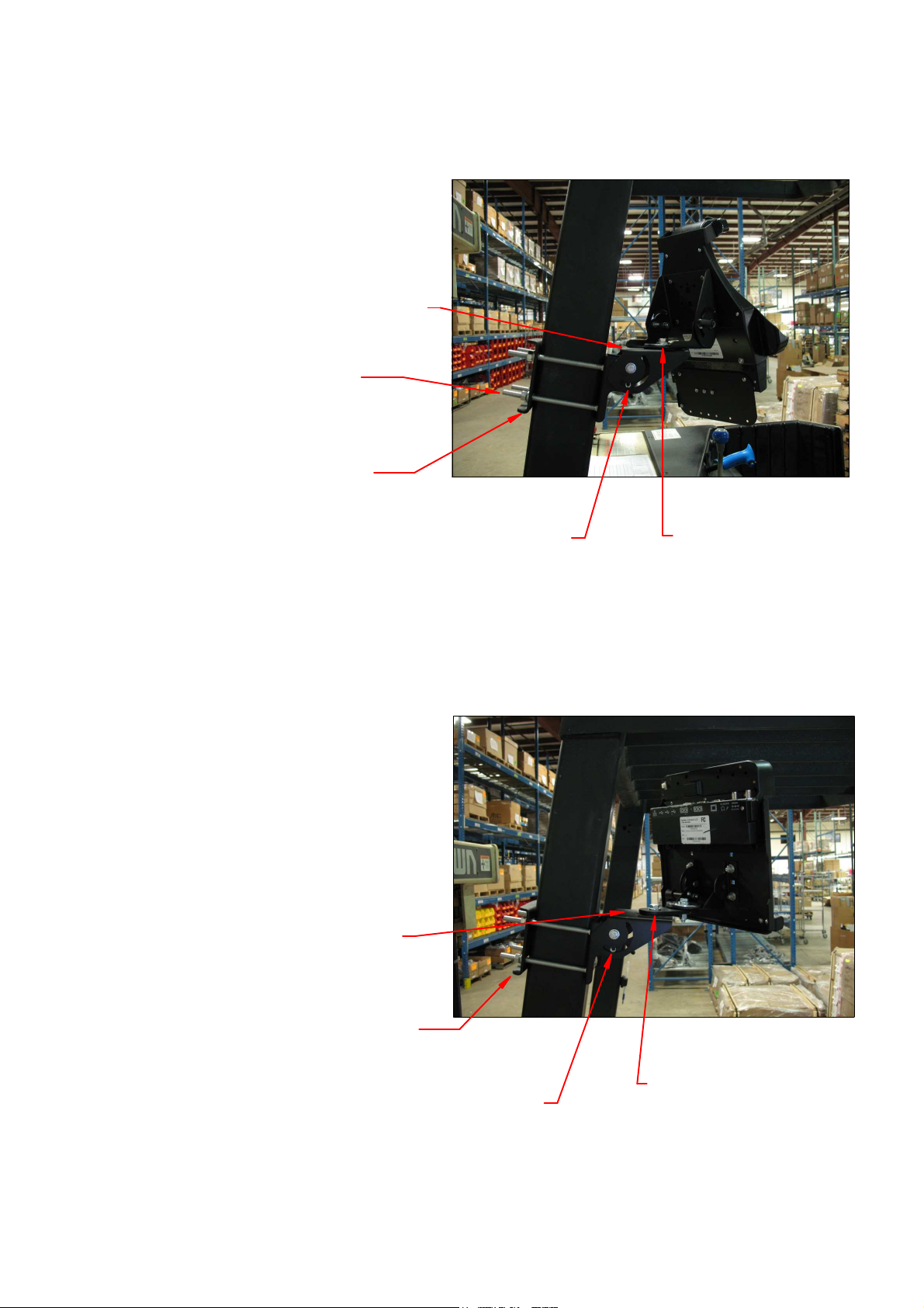
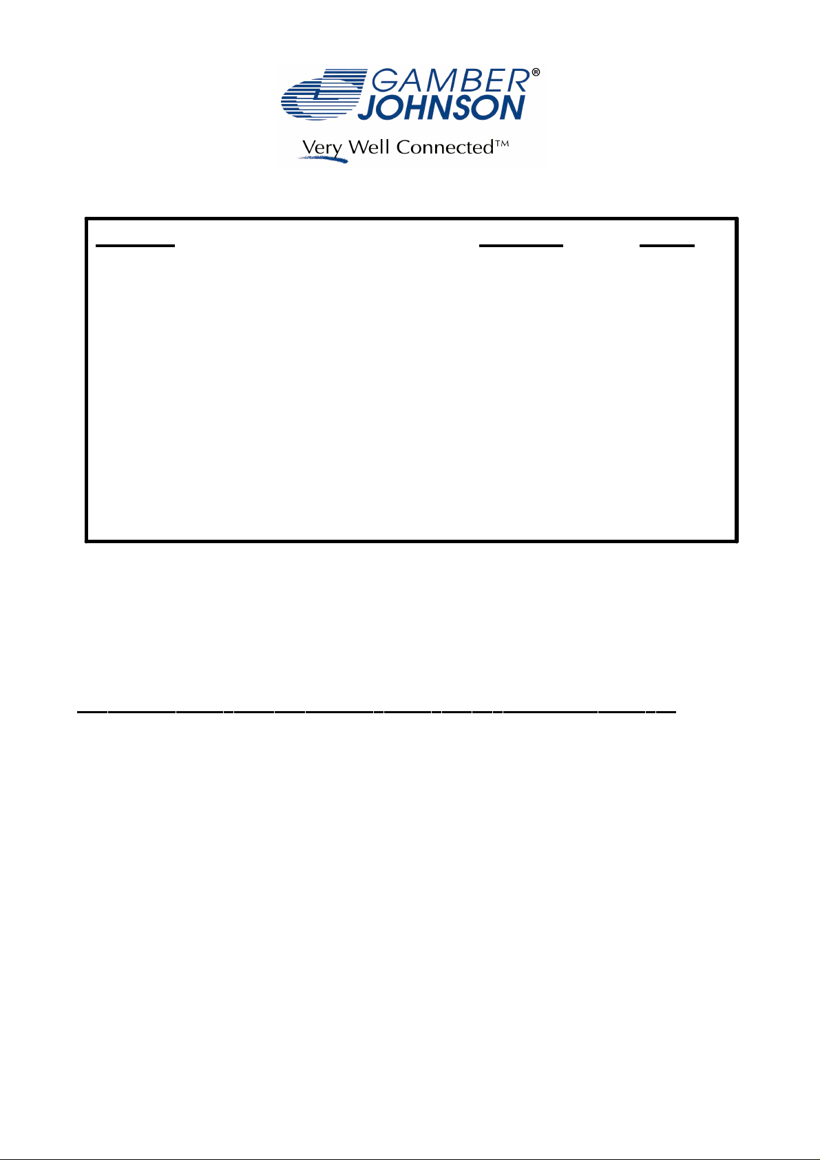
Figure 1. - Example of Dual Clam Shell Assembly
7160-0366 = Full Assembly with Small Back Plate
7160-0367 = Full Assembly with Adapter and
Large Back Plate
Position so this surface
is relatively level
Position the 3/8 bolts as close to
the pillar as possible to prevent
bowing the components
Note orientation of bends
on backer plate
Note: 1/4" bolts and flat washers have been provided
in the hardware bag and can be installed in the open
location opposite the lever handles to lock the clam
shells in place.
Figure 2. - Example of Clam Shell with
0-90 Clevis and 3" Arm
7160-0364 = Full Assembly with Small Back Plate
7160-0365 = Full Assembly with Adapter and
Large Back Plate
Position so this surface
is relatively level
Note: The 3/8" pivot bolt
can be tightened to lock
the mount in place.
Note orientation of bends
on backer plate
Note: 1/4" bolts and flat washers have been provided
in the hardware bag and can be installed in the open
location opposite the lever handles to lock the clam
shells in place.
Note: The 3/8" pivot bolt
can be tightened to lock
the mount in place.
2 of 5
Page 3

The components to build a pillar mount can also be purchased separetly if required.
The hardware to assemble the Secondary Clam Shell or 0-90 Clevis to the lower
portion are provided with each assembly (7160-0371 or 7160-0356).
3/8" hex bolt
3/8" flat washer
Secondary Clam Shell
7160-0371
nylon bearing
bearing backup plate
3/8" flat washer
bearing backup plate
nylon bearing
nylon bearing
Lower Clam Shell Mount
7160-0357 or
7160-0370
0-90 Clevis
7160-0356
3/8" flat washer
3/8" nulok hex nut
nylon bearing
3" arm
3/8" nylok hex nut
3/8 hex bolt
3/8 flat washer
bearing backup plate
nylon bearing
3/8 hex bolt
3/8 flat washer
nylon bearing
Lower Clam Shell Mount
7160-0357 or
7160-0370
nylon bearing
bearing backup plate
3/8" flat washer
3/8 nylok hex nut
3 of 5
Page 4

An Extention Tube Assembly (7160-0363) can be added to a pillar to move the
loction of the pillar mount assembly to the front or side of the fork truck as
required. This assembly attaches to the pillar with 3/8 hardware that are provided
with the mount.
7160-0363
Views of pillar mount 7160-0364
mounted on an Extension tube to
position the computer equipment
in front of the fork truck
Note orientation of bends
on backer plate
Note orientation of bends
on backer plate
4 of 5
Page 5

The Roof Mounts (7160-0368 & 7160-0369) hang from the upper cage of a fork
truck. The mount compresses the cage between the lower portion of the mount and
the back plate using 3/8" hardware.
Back plate
Lower portion
of mount
7160-0368 7160-0369
View of roof mount 7160-0368 mounted to upper
rack of fork truck
5 of 5
 Loading...