

Page 1
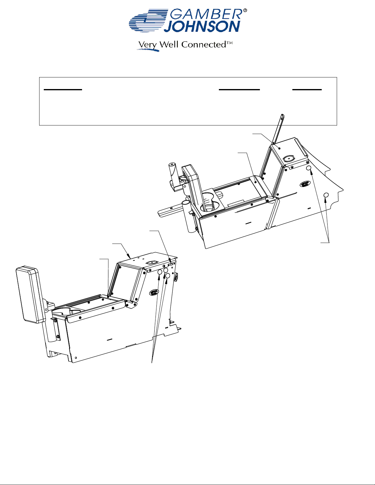
INSTALLATION INSTRUCTIONS
Product
7160-0409 THRU 7160-0412
FORD NGPI CONSOLE SEDAN & UTILITY, 2012+
7120-0579 Cable Kit
7160-0431 Filler Panel Assembly
Center Brace
USB/Audio
RELOCATION
Top Plate
Center Brace
Revision
Rev.E
Printing Spec:
Form
INST-568
PS-001
Top Plate
12v Knockouts
7160-0409 Shown
Armrest and Cupholder are
not included with 7160-0410
Note:
12v Knockouts
If there is no factory front console plate
(Top Plate) installed, use hardware bag
7160-0411 Shown
7120-0630(included) for required hardware
Armrest and Cupholder are
not included with 7160-0412
Product Mounting Disclaimer
Product Mounting Disclaimer
Gamber-Johnson is not liable under any theory of contract or tort law for any loss, damage, personal injury, special, incidental or consequential damages for personal injury or other damage
Gamber-Johnson is not liable under any theory of contract or tort law for any loss, damage, personal injury, special, incidental or consequential damages for personal injury or other damage
of any nature arising directly or indirectly as a result of the improper installation or use of its products in vehicle or any other application. In order to safely install and use Gamber-Johnson
of any nature arising directly or indirectly as a result of the improper installation or use of its products in vehicle or any other application. In order to safely install and use Gamber-Johnson
products full consideration of vehicle occupants, vehicle systems (i.e., the location of fuel lines, brakes lines, electrical, drive train or other systems), air-bags and other safety equipment is
products full consideration of vehicle occupants, vehicle systems (i.e., the location of fuel lines, brakes lines, electrical, drive train or other systems), air-bags and other safety equipment is
required. Gamber-Johnson specifically disclaims any responsibility for the improper use or installation of its products not consistent with the original vehicle manufactures specifications
required. Gamber-Johnson specifically disclaims any responsibility for the improper use or installation of its products not consistent with the original vehicle manufactures specifications
and recommendations, Gamber-Johnson product instruction sheets, or workmanship standards as endorsed through the Gamber-Johnson Certified Installer Program.
and recommendations, Gamber-Johnson product instruction sheets, or workmanship standards as endorsed through the Gamber-Johnson Certified Installer Program.
© copyright 2012 Gamber-Johnson, LLC
If you need assistance or have questions, call Gamber-Johnson at 1-800-456-6868
1/3
Page 2

Sedan:
1. Remove the stock tunnel plate by removing the
6 bolts.
2. The harness on the right side of the YAW sensor
(located on the transmission tunnel) may impede
box installation. For ease of installation, pull up
on harness to disconnect the push fastener
attaching the harness to the transmission tunnel.
3. The rear mounting points may be hidden under
the flooring. Carefully cut the flooring as shown
to expose the mounting points (Fig 1).
4. Slide console box into place.
5. Attach console to transmission tunnel using OEM
hardware.
Utility:
1. Remove the lower dash trim panels on either side
of the dash (Fig 2).
Fig 1 - Rear Mounting Bracket, Carpet Cut to Revel Threaded Inserts
2. Remove the stock tunnel plate by removing the 6
bolts.
3. Remove the USB/Audio/12v jack Trim Panel (Fig 2)
and disconnect the USB, Audio and 12v cables.
4. Relocate OEM Module to under dash area (Fig. 3)
5. The harness on the right side of the YAW sensor
(located on the transmission tunnel) may impede
box installation. For ease of installation, pull up
on harness to disconnect the push fastener attaching
the harness to the transmission tunnel.
6. Remove the Top Plate from the console box.
7. Slide the console box into place.
8. Attach the console to the transmission tunnel using
the OEM hardware.
Fig. 3 - OEM Module located on backside of Trim Panel
9. Attach the Lower Dash Trim Panel to the console box
by placing the lower lip of the Trim Panel into the hook
on the bottom of the console box (Fig 4).
Lower Dash
Trim Panel
USB/Audio
Trim Panel
Fig 2 - Utility Lower Dash
10. Attach the top of the Lower Dash Trim Panel to the
console box using the supplied Trim Hooks (Fig 4).
Note that the left Trim Hook has an "L" cut out of it.
It may be easier to remove the Top Plate when
installing the Lower Dash Trim Panels.
11. Snap the Lower Dash Panels back into place.
2/3
Page 3

Left Trim Hook
Lower Dash Trim Panel
Hooked into Console Box
Fig 4 - Installing Lower Dash
Trim Panels
Sedan and Utility:
Install the armrest (7160-0409 & 7160-0411) into the tube and adjust to the desired
height/orientation then tighten the bolt under the armrest. Note: Armrest is not included with
7160-0410 or 7160-0412 but can be ordered separetly. The armrest mounting bracket can be
flipped over to lower the armrest if desired or if used with a Printer Armrest.
The cup holder (MCS-INTCUP) can be placed anywhere along the horizontal length of the box.
Note: The cup holder is not included with 7160-0410 or 7160-0412 but can be ordered separetly.
The Top Plate and Center Brace on both console boxes are designed to be removable to aid in
installation and cable routing. If either item is removed Gamber-Johnson recommends
reinstalling the screws with a drop of Blue 242 Loctite to prevent loosening.
Both boxes have knockouts for 12v accessory outlets (7160-0063). To install simply punch out
the desired knockout and install the 12v outlet. The 12v outlet will need to be hardwired into
the vehicles power system. An additional 12v accessory outlet can be purchased for the second
knockout if desired.
7120-0579 & 7160-0431 Accessories:
On the Utility vehicle, the USB and Audio jacks can be relocated to the side of the console box
using kit #7120-0579 or to a Filler Panel #7160-0431 mounted in the Console Box. To install the
Audio Cable, screw the threaded jack into the threads on the side of the box or on the Filler
Panel and then connect the plug to the vehicles audio jack. To install the USB cable, use the
screws provided with the cable to screw the bulkhead connector to the threaded inserts in the
side of the box or on the Filler Panel and then connect the plug to the vehicles USB port. It may
be desirable to reinforce the connections with electrical tape or shrink wrap in order to keep
the connections inside the console secure.
7120-0579
USB Cable
Audio Cable
Audio Cable
7160-0431
USB Cable
3/3
 Loading...